Trauma Radiographic Procedures
 Call Kai
 Learn
Learn Practice Test
 Spaced Repetition
 Match
Match Flashcards
 Knowt Play
1/27

There's no tags or description
Looks like no tags are added yet.
Name | Mastery | Learn | Test | Matching | Spaced | Call with Kai | Chat |
|---|
No analytics yet
Send a link to your students to track their progress
28 Terms
Common Initial Trauma Exams
XTL C-Spine
AP CXR
AP ABD/Pelvis
C-Spine Routine
Lumbar Spine
Skull
Lower Extremities
Upper Extremities
Note: The exams listed are initial exams. More comprehensive exams, which include full routines, and additional exams of the body may be ordered by the physician if deemed necessary. You may have also noticed that the exam of the skull is not included. In larger trauma centers, examination of the cranium is usually completed by CT because of its availability. However, some trauma centers still obtain skull radiographs, and most facilities that do not have CT available will perform skull exams, therefore the radiographer must be knowledgeable regarding skull radiography
Lateral C-Spine
Must be done first
Attending physician must review and clear
Move patient’s head and neck as little as possible
Patient supine on backboard in cervical collar - Dorsal Decubitus Position
Patient should relax shoulder as much as possible and look straight ahead
Vertical IR in holder and centered at C4
Central ray is horizontal and perpendicular to IR
Central ray enters MCP at level of CR
72” SID
Cervical Thoracic
If all seven vertebrae, and C7-T1 are not clearly visible on the lateral, a swimmers must be performed
Do not move patient’s arms without permission from physician
Patient supine on backboard in cervical collar - Dorsal Decubitus Position
Ask patient to raise arm opposite the x-ray tube overhead
Relax shoulder closer to x-ray rube - do not force
Vertical IR centered just above jugular notch
Horizontal CR centered to C7-T1 interspace and midcoronal plane
If shoulder can’t separate a 3-5 degree caudal angle may be used
40” SID
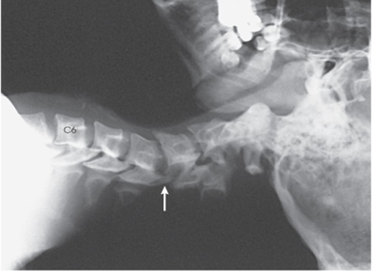
X Table Lateral C-Spine
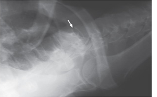
X Table Lateral Cervicothoracic
AP Axial C-Spine
Patient is supine
Usually immobilized with collar and spine board
Place IR under spine board, if present, centered to C4
Head and shoulder without rotation
Ask patient to look straight ahead
Do not rotate head
CR directed 15-20 degrees cephalic to enter MSP and C4
Image demonstrates C3-T2, including all soft tissues
If backboard is present, unavoidable artifacts may be seen
AP Oblique C-Spine
Patient supine on backboard in cervical collar - Dorsal Decubitus Position
Head and shoulders without rotation. Ask patient to look straight ahead. Do not rotate head
CR has double angle
45 lateralmedially and 15-20 cephalic
CR enters slightly lateral to MSP at C4
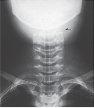
AP Axial C-Spine
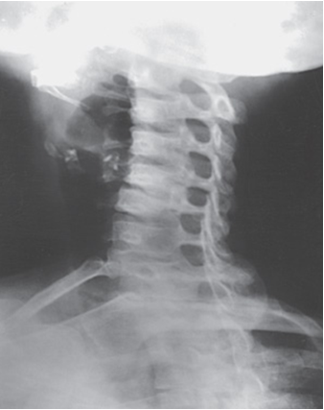
AP Oblique C-Spine
Open Mouth C-Spine
If condition allows have patient open mouth as far as possible without moving head or neck
CR may be angled if needed to parallel the line from lower margin of upper teeth to base of skull (mastoid tips)
C-Spine Fuchs
Cervical spine remains neutral in collar
Central ray is angled to match MML
Angle CR cephalic 35-40 degrees as needed to align CR parallel to the MML
CR enters just beneath mentum of mandible
Demonstrates dens within foramen magnum when open mouth not possible
Thoracic and Lumbar
Always perform dorsal decubitus positions before AP
Vertical grid IR below level of tabletop
Horizontal beam
Top of IR 1.5-2” above shoulders for thoracic. Centered to T7. 3-4” inferior to jugular notch
Centered to level of iliac crests for lumbar L4-L5
Laterals centered MCP
AP centered MSP
Have patients cross arm on anterior chest or above head
Chest
Supine position used if general survey image of chest desired
Check for need to demonstrate air-fluid levels
If air-fluid level are suspected, use dorsal decubitus position
If patient’s condition permits, lateral decubitus position with patient lying on affected side will also show air-fluid levels
Obtain help to lift patient for IR placement
Mark entrance and exit wounds, if present
Top of IR placed about 1.5-2” (3.8-5 cm) above shoulders
CR MSP and a level 3” below jugular notch
Angle 3-5 degrees caudal to match long axis of sternum
Arms abducted
MCP parallel to IR
Use maximum SID to reduce heart magnification
Exposure at the end of deep inhalation
AP Abdomen
If transfer to x-ray table is not possible, obtain lift help for IR placement
IR centered to MSP at level of iliac crests
Check for possibility of fluid accumulation in abdominal cavity
Affects exposure factors
Requires close monitoring of patient for status change during procedures
Mark entrance and exit wounds, if present
Align shoulders and hips in same plane
MCP parallel to table
CR perpendicular to center of IR
Image demonstrates entire abdomen with pubic symphysis visible at lower border
Instruct patient to exhale and hold their breath
Decubitus Abdomen
Verify that patient movement is possible
Left lateral decubitus position shows free air
If fluid accumulation is of interest, the side down must be elevated off stretcher
Carefully and slowly turn patient
MCP is vertical
Center IR 2” above the crests to include diaphragm
Instruct patient to exhale and hold their breath
Pelvis
Pelvic fractures have a high risk of hemorrhage - pay close attention to patient for status change. Up to 50% of pelvic fractures result in death due to vascular damage and shock
Obtain lift help for IR placement if transfer to x-ray table is not possible
IR centered 2” (5 cm) above pubic symphysis or 2” (5 cm) below ASIS
MCP parallel to IR
Lower limbs usually not internally rotated in trauma cases
Ensure arms are not in anatomy of interest
CR perpendicular to center of IR
Exposure made on suspended respiration
Image demonstrates entire pelvis and proximal femora
Femoral necks foreshortened
Axiolateral Hip Danelius - Miller Method
Cross table lateral
Do not attempt to internally rotate affected limb
Patient supine
Position grid IR parallel with femoral neck centered to most prominent portion of greater trochanter, level midline of hip
Obtain appropriate assistance to elevate non injured hip
CR is horizontal and perpendicular to the IR at level of femoral neck
Modified Axiolateral Hip Clement Nakayama Method
Used for patient with suspected bilateral hip fractures
Position a grid IR aligned parallel to the femoral neck at a height to place the center of the hip on the IR
Top of the grid IR back 15 degrees
Do not attempt internal rotation of limb
CR 15 degrees posteriorly and aligned to femoral neck and grid IR
Lateral Skull
Patients with head trauma are often referred to CT first
When x-rays are ordered, a general survey requires AP and Lateral projections
Lateral projection uses dorsal decubitus position
Lateral cranium
Elevate head on radiolucent sponge
Only after ensuring C-spine injury has been ruled out
Place vertical IR centered to cranium
Make sure interpupillary line is perpendicular to IR and MSP is vertical
Horizontal CR enters center of IR and patient at 2” (5 cm) above EAM
AP and AP Axial Reverse Caldwell Skull
Demonstrate frontal cranium
OML and MSP perpendicular to IR
CR perpendicular to nasion AP
CR 15 degrees cephalic for AP Axial Reverse Caldwell
Image Magnified
AP Axial Towne Method Skull
Demonstrate posterior cranium
Angled 30 degrees caudal to OML
Angled 37 degrees caudal to IOML
Central ray passes through EAM exits foramen magnum
OML Positioning with patient’s with C-Collar: AP 0 Degrees to OML
Angle CR parallel to OML: With a patient in a c-collar, this often occurs approximately 10-15 degrees caudal, but each patient and situation will be different
Center CR to glabella; then center IR to projected CR

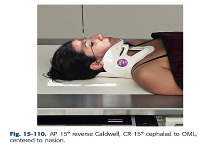
OML Positioning with patient’s with C-Collar: AP 15 degree reverse Caldwell projection
Angle CR 15 degree cephalic to OML: To accomplish this, first find the OML on the patient; this varies in patients in cervical collars with the neck extended. Then angle the CR 15 degrees cephalic to the patient’s OML, which will result in appearance of the CR close to a perpendicular beam relationship to the patient and the IR.
Center CR to nasion; then center IR to projected CR
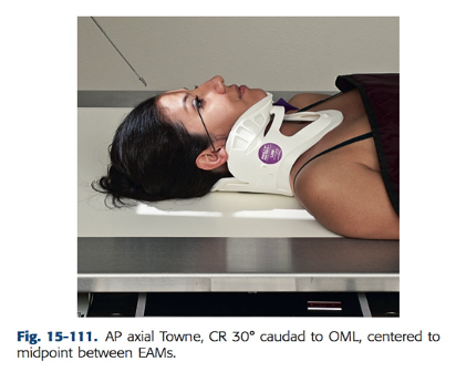
OML Positioning with patient’s with C-Collar: AP Axial Towne Projection
Angle CR 30 degrees caudal to OML or 37 degrees caudal to IOML. Once again, note that a patient in a c-collar with the neck extended will have OMLs and IOMLs that vary from the conventional parallel and perpendicular relationships formed through routine positioning
Center CR to pass midway between EAMs and exiting the foramen magnum. This centers CR to MSP 2 ½ “ (6 cm) above superciliary arch; then center IR to projected CR
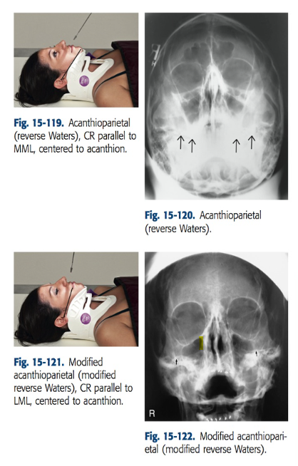
Facial; Acanthioparietal - Reverse Waters
This projection best visualizes facial bone structures and the maxillary region by projecting the maxilla and maxillary sinuses above the petrous ridges
Angle CR cephalic as needed to align CR parallel to MML
Center CR to acanthion and then center IR to projected CR
Facial; Optional Modified Acanthioparietal Reverse Waters
This projection best demonstrates the floor of the orbits and provides a view of the entire orbital rims. Petrous ridges are visualized in midmaxillary sinus region
Angle CR cephalic as needed to align CR parallel to the lipsmeatal line (LML)
Center CR to acanthion; then center IR to prjected CR
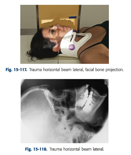
Facial; Lateral
Horizontal beam is essential for visualization of intracranial air fluid levels
Center CR to the zygoma, midway between the outer canthus and EAM
Place lengthwise IR closest to the side of interest and center to the CR
Head placement on table because don’t need back of skull
Upper and Lower Limbs
Only move the patient when absolutely necessary and get assistance to do so
The patient should be moved only after it is determined by qualified medical personnel confirms that it is safe to do so
When moving a trauma patient, all injured limbs should be supported to prevent further injury
Two projections of each body part should be taken, They should be a 90 degree angles, or as near to that as possible
A horizontal beam will be necessary in many cases
If the patient is conscious, an explanation should be given before they are moved
This helps the patient prepare for the move and they may be able to assist to minimize the pain
When long bones are being imaged, both joints must be included
If it is necessary to use two projections, the joint and the point of injury should be on one image, and the second joint should be radiographed separately
Images similar to routine radiographs can be obtained with little or no movement of the patient, it the normal central ray entrance and exit points are maintained through tube angulation