Radiographic Procedures 2 (155) Lumbar Vertebrae, Sacrum, and Coccyx
1/40
There's no tags or description
Looks like no tags are added yet.
Name | Mastery | Learn | Test | Matching | Spaced |
|---|
No study sessions yet.
41 Terms
Lumbar spine
five total
occupy posterior abdominal region
features:
transverse processes smaller than T-spine
pars interarticularis; part of lamina between articular processes
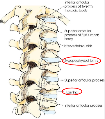
Lumbar vertebra
body
2 pedicles
2 transverse processes
2 laminae
superior and inferior articular processes
spinous process
accessory process; formed posterior of the transverse process
mamillary process; forms off of the superior articular process
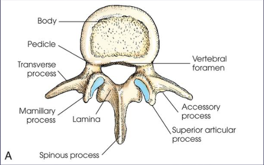
Zygapophyseal joint
shown in an AP or PA oblique projection;
AP oblique:
LPO, left side
RPO, right side
PA oblique:
RAO, left side
LAO, right side
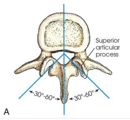
Intervertebral foramina
shown in a lateral projection, 90 degree rotation of patient
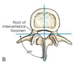
Sacrum
formed by the fusion of five sacral segments into curved, triangular bone
wedged between iliac bones of the pelvis
articulation - sacroiliac (SI) joints
anatomic features:
promontory
sacral canal
pelvic sacral foramina
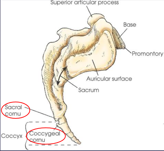
sacral cornu
males: longer, narrower, more evenly curved, and more vertical in position
females: more acutely curved
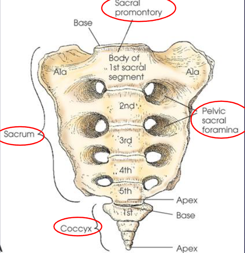
Coccyx
formed by fusion of three to five rudimentary vertebrae
curves inferiorly and anteriorly from articulation with sacrum
coccygeal cornu
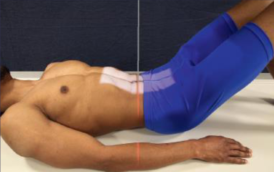
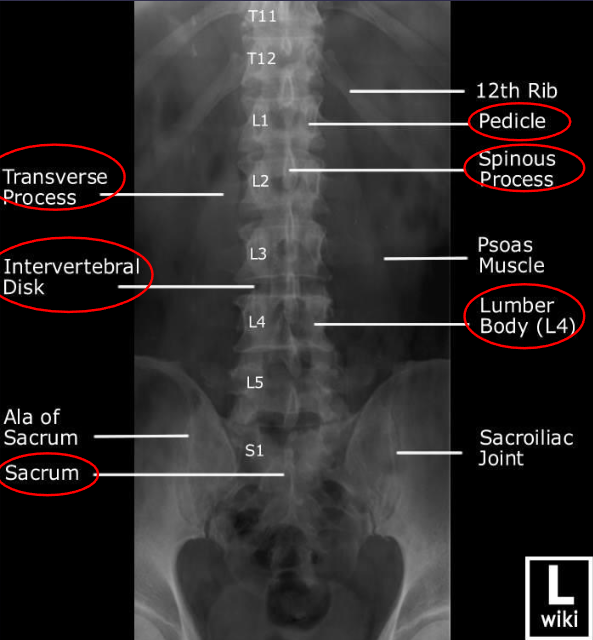
AP L-spine
patient position:
supine or upright
part position:
MSP centered to midline
shoulders and hips in same horizontal plane
arms crossed on chest
reduce lordosis by flexing hips and knees to place lower back closer to table
respiration:
suspended at the end of expiration
CR:
perpendicular to IR
for lumbosacral: enters patient at iliac crests (L4)
for lumbar: enters 1 ½ inches above iliac crests
collimation:
for lumbosacral: 8 × 17 inches
for lumbar: 8 × 14 inches
SID:
48” to reduce distortion and open intervertebral disk spaces
AP L-spine image criteria
lumbar bodies
open intervertebral disk spaces
interpediculate spaces (between pedicles)
spinous processes
transverse processes
sacrum
coccyx
lower thoracic vertebrae
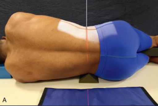
Lateral L-spine
demonstrates intervertebral foramina
patient position:
recumbent or upright
part position:
true lateral, MCP vertical
knees flexed and superimposed
arms, with elbows flexed, at right angle to body
place place radiolucent support under lower spine to place horizontal, if needed (for perpendicular CR)
respiration:
suspended at the end of expiration
CR:
perpendicular to IR (with sponge)
enters MCP at iliac crests (L4)
if spine is not horizontal, angle caudad 5-8 degrees (without sponge)
collimation:
8 × 17 inches
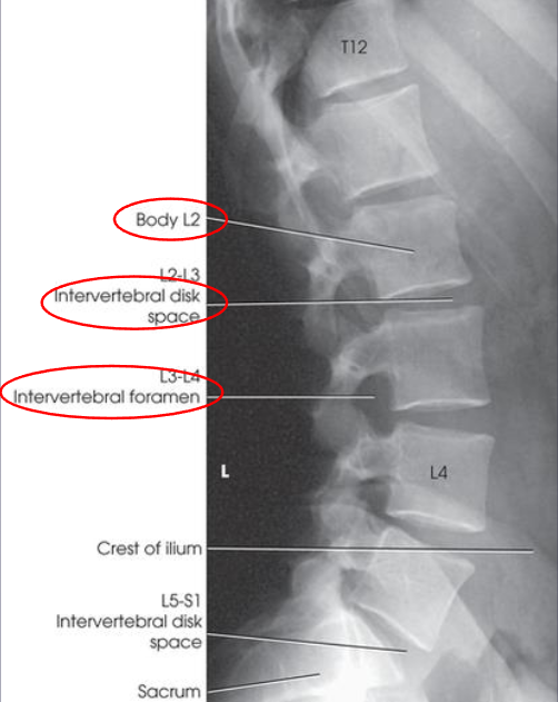
Lateral L-spine image criteria
all five vertebral bodies
intervertebral disk spaces
intervertebral foramen
upper sacrum
superimposed posterior margins of bodies
nearly superimposed iliac crests (if CR is not angled)
spinous processes in profile
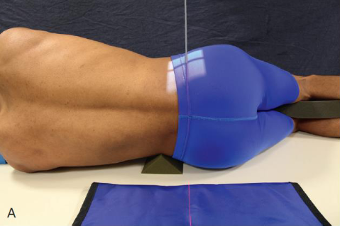
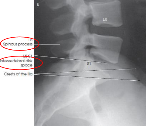
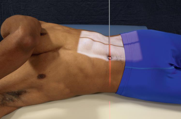
Lateral L5-S1
patient position:
lateral recumbent
part position:
MCP perpendicular to IR
hips extended
superimposed knees, may be slightly flexed
with elbows flexed, place arms at right angle to body
support lower spine in horizontal position in same manner as for lateral projection
respiration:
suspended
CR:
when spine is horizontal, perpendicular; 2 inches posterior to ASIS and 1 ½ inches inferior to iliac crest
if spine is not horizontal:
angle 5 degrees caudad for males
angle 8 degrees caudad for females
francis method suggests angling caudad for smaller/average waists and angling cephalad for larger waists
collimation:
6 × 8 inches
Lateral L5-S1 image criteria
lumbosacral junction
lower one or two lumbar vertebrae
upper sacrum
open lumbosacral intervertebral disk space open
iliac crests closely superimposing each other (perpendicular CR)
AP oblique L-spine
demonstrates zygapophyseal joints closest to IR
both sides examined for comparison
patient position:
recumbent or upright
part position:
45 degree rotation
radiolucent support under elevated side
respiration:
suspend at the end of expiration
CR:
perpendicular to IR
2 inches medial to elevated ASIS at L3 (1 ½ inches above iliac crests
collimation:
9 × 12 inches (10 × 12 inch IR)
9 × 14 inches (14 × 17 inch IR)
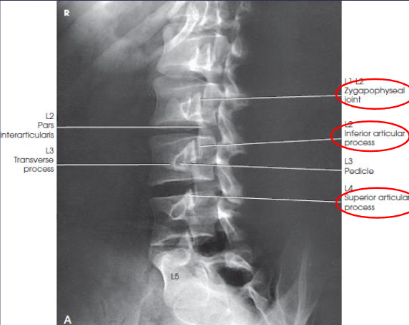
AP oblique L-spine image criteria
lumbosacral spine or both
articular processes
zygapophyseal joints, closest to IR
open and uniformly visible thorugh the vertebral bodies
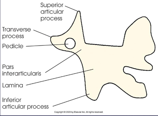
Scottie dogs
when the joint is not well seen, and the pedicle is anterior on the vertberal body, the patient is not rotated enough
when the joint is not well seen, and the pedicle is posterior on the vertebral body, the patient is rotated too much
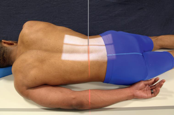
PA oblique L-spine
demonstrates the zygapophyseal joints farthest from IR
both sides demonstrated for comparison
patient position:
upright or recumbent
part position:
45 degree rotation
respiration:
suspended at the end of expiration
CR:
perpendicular to IR
enters 2 inches lateral to elevated spinous process and 1 ½ inches above iliac crest
collimation:
9 × 14 inches
PA oblique L-spine image criteria
zygapophyseal joints farthest from IR
T12-L1 articulation
Scottie dogs
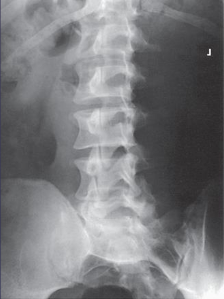
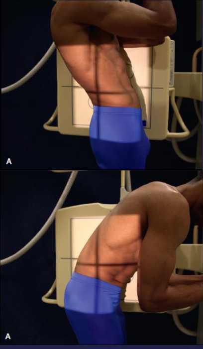
Lateral L-spine (flexion and extension)
patient position:
upright or recumbent
MCP centered to midline of the grid
part position:
flexion: patient bends forward
extension: patient bends backward
IR centered at level of spinal fusion (if present)
repiration:
suspended
CR:
perpendicular to spinal fusion or L3
collimation:
14 × 17 inches
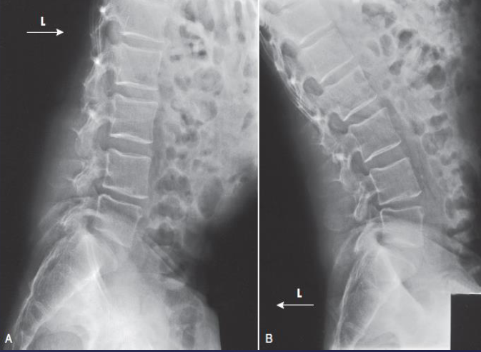
Lateral L-spine (flexion and extension) image criteria
motion in the area of a spinal fusion (if present)
herniated disk (if present)
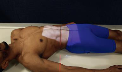
AP L-spine (left and right bending)
patient position:
upright or supine
mSP centered to midline of grid
part position:
first radiograph with maximum right bending
second radiograph with maximum left bending
cross patient’s leg on the opposite side to be flexed over the other leg
move the patient’s heels toward the side that is flexed
mvoe the shoulders directly lateral as far as possible without rotating the pelvis
respiration:
suspended
CR:
perpendicular to IR
enters L3, 1-1 ½ inches above iliac crests
collimation:
10 × 12 or 14 × 17 inches
AP L-spine (left and right bending) image criteria
lumbar vertebrae in maximum bending
integrity of spinal fusion
site centered and including superior and inferior vertebrae
scoliosis - structural changes in the vertebrae (if present)
herniated disk (if present)
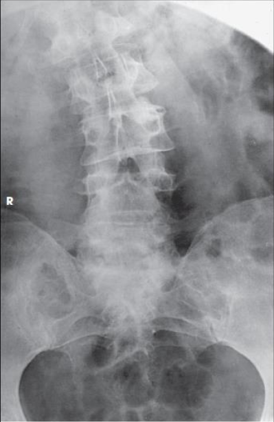
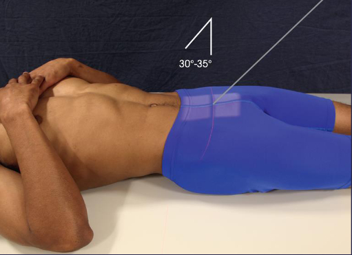
AP axial SI joints (Ferguson)
patient position:
supine
part position:
MSP centered to IR
extend lower limbs, or abduct thighs and place vertical
respiration:
suspended
CR:
cephalad angle
30 degrees in males
35 degrees in females
enters MSP at 1 ½ inches above pubic symphysis or
2-2 ½ inches inferior to ASIS
collimation:
8 × 10 or 10 × 12 inches
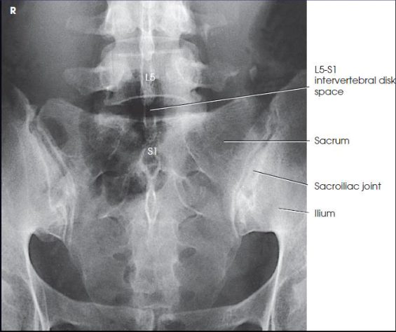
AP axial SI joints (Ferguson) image criteria
lumbosacral joint
symmetric SI joints
sacrum
open intervertebral disk space between L5 and S1
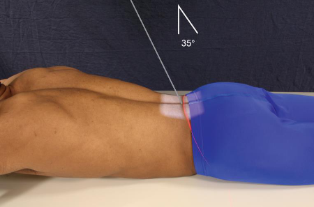
PA axial SI joints
patient position:
prone
part position:
MSP centered
respiration:
suspend
CR:
35 degrees caudad
enters L4 spinous process
collimation:
6 × 8 inches
PA axial SI joints image criteria
lumbosacral joint and both SI joints free of superimposition
AP oblique SI joints
demonstrates SI joint farthest from IR
both sides are examine for comparison
patient position:
supine
part position:
25-30 degree rotation
support body in position
long axis parallel with table
IR centered at level of ASIS
respiration:
suspended
CR:
perpendicular to IR
1 inch nedial to elevated ASIS
collimation:
6 × 10 or 6 × 12 inches
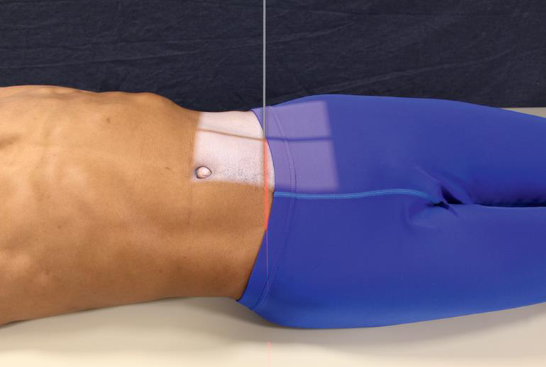
AP oblique SI joints image criteria
SI joint farthest from IR
RPO, left side
LPO, right side
open SI joint space with minimal overallping of ilium and sacrum
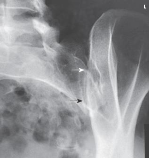
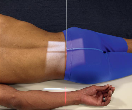
PA oblique SI joints
demonstrates SI joint closest to IR
patient position:
prone
part position:
25-30 degree rotation
support elevated side
respiration:
suspended
CR:
perpendicular to IR
1 inch medial to ASIS closest to IR
PA axial oblique can be obtained with an angle of 25-30 degrees caudad to enter L5 spinous process
collimation:
6 × 10 inches
PA oblique SI joints image criteria
SI joint closest to IR:
LAO, left side
RAO, right side
Scottie dog
AP axial sacrum
patient position:
supine
may also be performed with patient prone (PA axial) if needed for comfort
part position:
MSP in midline of table
ASIS equidistant from grid
arms in comfortable, symmetric position out of field
support knees with sponge
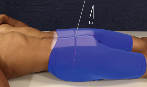
CR:
15 degrees cephalad
15 degrees caudad for PA
enters MSP 2 inches superior to pubic symphysis
enters MSP at level of sacral curve for PA
collimation:
10 × 12 inches
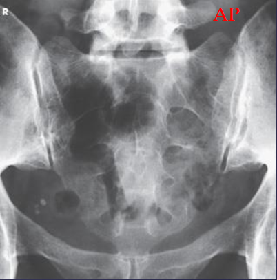
AP axial sacrum image criteria
sacrum free of superimposition
free of forshortening, with the sacral curvature straightened
pubic bones not overlapping the sacrum
AP axial coccyx
patient position:
supine
may also be performed with patient prone (PA axial) if needed for comfort
part position:
MSP in midline of table
ASIS equidistant from grid
arms in comfortable symmetric positon out of field
support knees with sponge
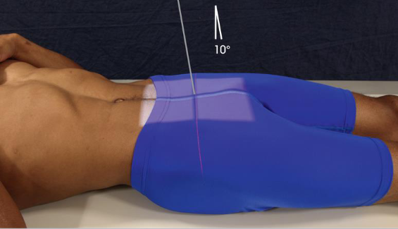
CR:
10 degrees caudad
10 degrees cephalad for PA
enters MSP 2 inches superior to pubic symphysis
enters MSP at coccyx for PA
collimation:
8 × 10 inches
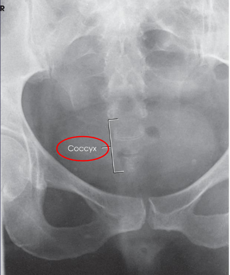
AP axial coccyx image criteria
coccyx free of superimposition
not superimposed by pubic bones/ pubic symphysis
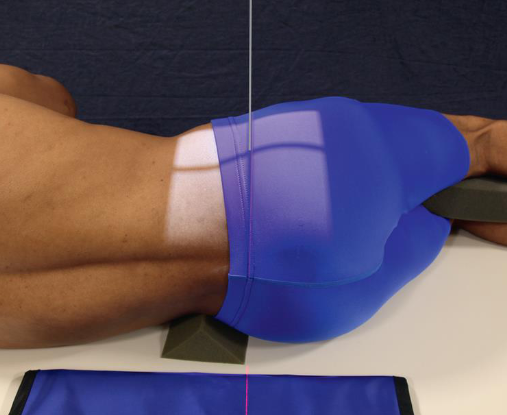
Lateral sacrum
patient position:
recumbent lateral
hips and knees flexed for comfort
part position:
arms at right angle to body
knees superimposed
support spine to horizontal position
interiliac plane perpendicular to IR
shoulders and pelvis in true lateral
MCP vertical
sacrum centered to IR
CR:
perpendicular to level of ASIS and to a point 3 ½ inches posterior
collimation:
10 × 12 inches
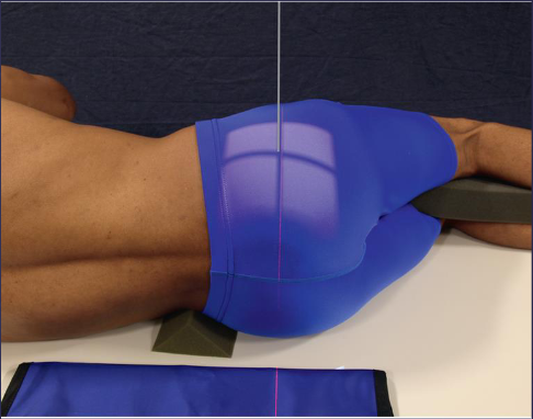
Lateral coccyx
patient position:
recumbent lateral
hips and knees flexed for comfort
part position:
arms at right angle to body
knees superimposed
support spine to horizontal position
interiliac plane perpendicular to IR
shoulders and pelvis in true lateral position
MCP vertical
sacrum centered to IR
CR:
perpendicular to 3 ½ inches posterior and 2 inches inferior to ASIS
collimation:
6 × 8 inches
closed collimation improves visibility
lead rubber behind patient absorbs scatter
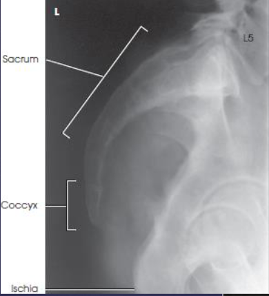
Lateral sacrum and coccyx image criteria
sacrum and coccyx
no rotation
closely superimposed posterior margins of the ischia and ilia, demonstrating no rotation
often combined for one image rather than two separate ones
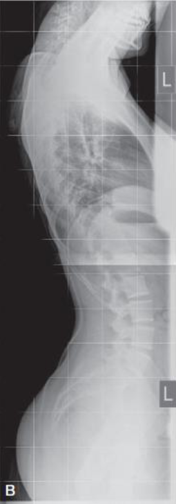
Scoliosis radiography
stitching applications
demonstrates amount/degree of curvature that occurs with force of gravity acting on body
also used to evaluate fixation devices, such as Harrington rods
bending studies used to differentiate between primary and compensatory curves
variety of devices and IR holders
all systems allow multiple images encompassing the entire spine to be captured without the need for repositioning the patient
acquired images combined, or stitched, by the computer system into composite image demonstrating entire spine in one image
note special radiation requirements
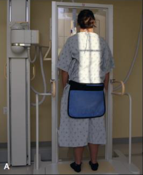
PA thoracolumbar
patient position:
upright, facing vertical grid
part position:
MSP centered to midline of the vertical grid device
ASIS equidistant to the IR
arms abducted and not in field
CR:
perpendicular to IR
centering points for each sequence will be dictated by the system used
a two (or three) image sequence is performed
collimation:
depends on the type of system used, as well as the extent of the patient’s scoliosis
PA thoracolumbar image criteria
entire spine from base of skull to tip of coccyx
cervical, thoracic, and lumbosacral spines
vertebral column aligned down the center of the image

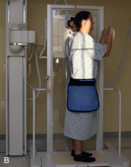
Lateral thoracolumbar
patient position:
upright, lateral
part position:
MSP centered with the IR
MCP perpendicular to midline of grid
arms at right angle to body or upward
position special ruler adjacent to spine if needed
CR:
perpendicular to IR
centering points for each sequence will be dictated by the system used
a two (or three) image sequence is performed
collimation:
depends on the type of imaging system used, as well as the extent of the patient’s scoliosis
Lateral thoracolumbar image criteria
entire spine from base of skull to tip of coccyx
entire cervical, thoracic, and lumbosacral spines
vertebral column aligned down the center of the image
