Polymers & Polymer Processing (L7&8)
1/45
There's no tags or description
Looks like no tags are added yet.
Name | Mastery | Learn | Test | Matching | Spaced | Call with Kai |
|---|
No analytics yet
Send a link to your students to track their progress
46 Terms
Advantages of polymer processing
Unlimited part geometries
net shape process
less energy than metals
doesn’t require finishing
General properties of polymers (relative to metals)
Low Density
Low strength & stiffness
Low electrical & thermal conductivity
Good chemical resistance
High coefficient of thermal expansion
Low useful temperature range
Tend to creep
IR radiation sensitive
creep
Permanent deformation that occurs in material over time that is subjected to a constant load
Polymer
Compound consisting of long-chain molecules
A polymer can contain millions of small units (monomers)
Derived from the Greek words
Poly = “many”
Meros = “part”
3 classifications of polymers
thermoplastic, thermosets, elastomers
thermoplastic
Chemical structure remains unchanged during heating and shaping
Comprises ~ 70% of total plastics tonnage
Thermosets
Undergo a curing process during heating and shaping, causing a permanent change in molecular structure, called cross‑linking
Once cured, they cannot be remelted
Elastomers
Exhibit extreme elastic extensibility when subjected to relatively low mechanical stress
Polymer melt
heating polymer so that it softens to the consistency of a liquid
Viscosity
is a fluids resistance to flow
Viscoelasticity
Material property that determines the strain that the material experiences when subjected to combinations of stress and temperature over time
combines both viscous and elastic behaviors
When stress is removed, material does not immediately return to its original shape; instead, the strain decays gradually
How does viscosity of a polymer melt change with increasing shear rate?
Viscosity decreases
Meaning it is Pseudoplastic (shear-thinning fluid)
Die Swell
the extrusion process experiences this issue with polymer melts and shape memory
Name the 6 processes by which products can be made from polymers
Injection Molding
Extrusion
Film Production
Fiber Production
Blowmolding
Thermoforming
Injection Molding
Most widely used process for making plastic parts. Capable of simple or complex 3-D parts in a wide variety of sizes and a wide variety of polymers
Needs:
Injection Molding Machine
Injection Mold Tool (aka the “mold”)
Polymer feedstock in form of pellets
Extrusion
Continuous length constant cross-section (“profile”) parts in a wide variety of sizes and a wide variety of polymers
Needs:
Extruder (machine)
Extrusion Die
Polymer feedstock in form of pellets
Film Production
Forms uniform thickness continuous sheet & film
Needs:
Film blowing/Extrusion Machine
Cooling, Slitting, Winding equipment
Typically starts with polymer pellets as feedstock
No mold/die required
Blow molding
Forms Pre-formed polymer part into more complex thin-walled parts (e.g., bottles/jugs)
Needs:
Blow molding Machine
Mold
Extruded Parison or Preform
Thermoforming
Forms flat sheet into 3-D parts with mostly uniform wall thickness
Needs:
Thermoforming Machine
Mold
Plastic Sheet Feedstock
Runner System
The network of channels within a mold that guides molten plastic from the injection molding machine's sprue to the mold cavity gates, where the plastic enters to form the final part
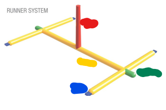
Name the parts of the runner system
Family Mold
A single mold base with multiple cavities designed to produce several different, but related, parts from the same material in a single molding cycle.
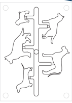
Multi Cavity Mold
A single mold base with multiple cavities designed to produce several of the same part in a single molding cycle
Principal components of an injection molding maching
injection unit, clamping unit
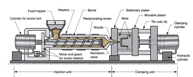
injection Unit function
Melts and delivers polymer melt
Operates much like an extruder
Clamping Unit function
Opens and closes mold each injection cycle
Injection unit components
Consists of barrel fed from one end by hopper containing supply of plastic pellets
Inside the barrel is a reciprocating screw with two functions:
Rotates for mixing and heating polymer
Acts as a ram (i.e., plunger) to inject molten plastic into mold
Clamping Unit Types
Mechanical (“Toggle”) clamp
Hydraulic clamp
Used on higher tonnage machines (150-1000 tons)
Can set tonnage at given positions during the stroke
Hydromechanical clamp
Capable of even larger tonnage (>1000 tons)
Rapidly move mold toward closing position (hydraulic cylinders)
Lock position (mechanical)
High-pressure hydraulic cylinders used to close the mold and build tonnage
Injection Molding — Mold Components
Cavity that imparts the part shape
Polymer supply “piping” (sprue/runner/gate)
Means for ejecting the part
Due to polymers high thermal expansion coefficients, what happens when molding?
Shrinkage occurs during solidification, so dimension of mold cavity must be made larger than specified part dimension
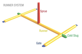
Cold Runner Mold Components
Sprue: main channel through which the plastic enters the mold
Runner: Connects all of the parts and spreads the plastic along the face where the halves of the mold meet
Gate: Controls the flow of the plastic into the cavity
Two Plate Cold Runner Mold
Cavity/core, distribution channel, ejection system, cooling system, and air vents
Three Plate Cold Runner Mold
Also includes a third plate which is used to separate parts from sprue and runner when mold opens
Allows automatic operation of molding machine!
Hot Runner Mold
eliminates the solidification of sprue and runner by locating heaters around the corresponding runner channels
Parting Line
where two halves of the mold meet
Taper
drafted walls ensure parts aren’t parallel to the pull direction
Ejector Pins
applies force to push the molded part out when the mold opens
Name the 8 common injection mold defects
Warping
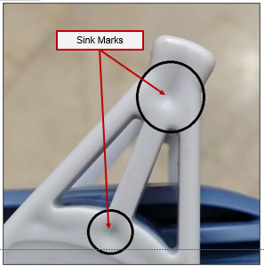
Sink marks
Knit lines/weld lines
Burn marks
Short shot
Flash
Voids
Flow marks
Warping
feature of the part (or the whole part) bends as the material cools
Sink Marks
type of warp that happens in the middle of a face when the material is too thick
Knit lines/Weld Lines
region where separate flows meet (as a result of flowing around holes and other features) may lead to deformations and discolourations

Burn marks
result from trapped air being compressed and heated to ignition temperature
Short Shot
dead-end areas can also lead to incompletely filled mold cavity
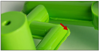
Flash
thin, excess plastic that escapes the mold cavity at the parting lines
Voids
hollow cavities that form within injection-molded plastic parts, caused by plastic shrinkage during cooling and improper packing
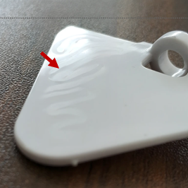
Flow marks
surface defect in injection-molded parts that appear as wavy lines or color variations, caused by uneven material flow and differing cooling rates, which can impact aesthetics.