A6 study guide
1/63
There's no tags or description
Looks like no tags are added yet.
Name | Mastery | Learn | Test | Matching | Spaced | Call with Kai |
|---|
No study sessions yet.
64 Terms
Atoms
Contain an equal number of protons, neutrons, and electrons.

Protons
have positive charge / contained in the atom's nucleus
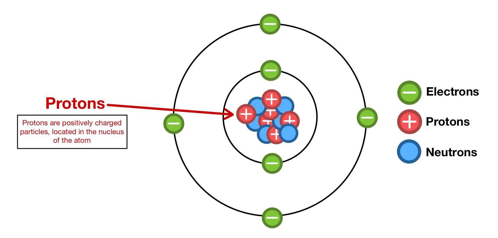
Neutrons
have no charge / contained in the atom's nucleus

Electrons
have a negative charge / orbit around the nucleus.

Valence ring
Outermost electron orbit of an atom (crucial for chemical bonding and reactions with other atoms)

Electromotive Force / EMF
An outside force is applied to create an imbalance of electrons, so the flow begins (Battery/ Alternator)
Battery
The positive terminal has a shortage of electrons, and the negative terminal has an excess of electrons
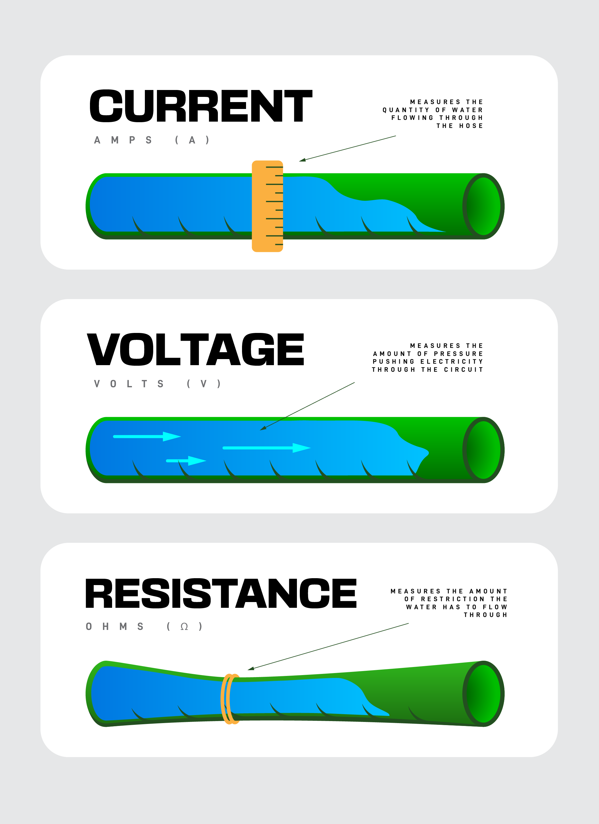
Voltage (Volts)
electrical pressure or potential difference that pushes electric charges (current) through a circuit (water pressure in pipes, where higher voltage means more "push" for electrons to flow and do work, like lighting a bulb.)
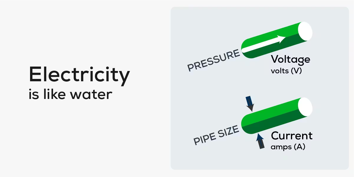
Current Flow (AMPS)
measures the rate of electron flow in an electrical circuit, like water flow in a pipe
Kilo
is Bigger (Big = divide by /1000)
( kV (kilo-volt) = 1,000 volts→1V=0.001kV)
( kA (kilo-amp) = 1,000 amps→1A=0.001kA)
( kΩ (kilo-ohm) = 1,000 ohms→1Ω=0.001kΩ)
Milli
Smaller (Small = multiply ×1000)
( mV (millivolt) = 1/1,000 volt→1 V=1,000 mV)
( mA (milliamp) = 1/1,000 amp→1 A=1,000 mA)
( mΩ (milliohm) = 1/1,000 ohm→1 Ω=1,000 mΩ)
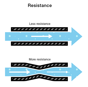
Resistance (Ohms)
the opposition a material presents to the flow of electric current (acting like friction to slow electrons)
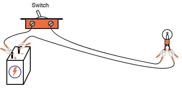
Control Device
a hardware component that manages or regulates a system, like a switch turning a motor on/off
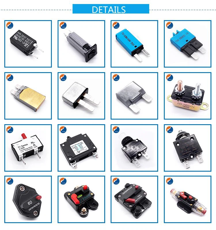
Circuit Protection Device
A safety component that automatically interrupts electrical current to prevent damage from overloads, short circuits, or faults ( Fuse, fusible link, circuit breakers)
Voltage Drop
Loss of electrical pressure (EMF) across a load (whether intended or not) is called “voltage drop” caused by the resistance of the wires and components
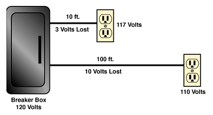
sum of all voltage drops
Equal the original amount of applied (source) voltage
Kirchhoff's Laws
2 fundamental rules
Kirchhoff's Current Law (KCL) Junction Rule- Rule: The total current entering a junction must equal the total current leaving it
Kirchhoff's Voltage Law (KVL) Loop Rule- Rule: The sum of all voltage rises (from sources like batteries) must equal the sum of all voltage drops (across resistors, etc.) in a closed loop.
Ohm’s Law
Fundamental relationship in electrical circuits: electric current (𝐼) is directly proportional to voltage (𝑉) and inversely proportional to resistance (𝑅)
Find Voltage with Ohm’s Law
𝑉 = 𝐼 × 𝑅
Find Amps with Ohm’s Law
𝐼 = 𝑉 / 𝑅
Find Ohms with Ohm’s Law
𝑅 = 𝑉 / 𝐼
when Voltage goes down
Current flow goes down, providing the Resistance stays the same
when Resistance in a circuit goes up
Current goes down providing the Voltage stays the same
When Resistance in a circuit goes down
Current will go up, providing the Voltage stays the same
Direct Current (DC)
Travels in one direction
Alternating Current (AC)
Reverses direction at specified time intervals measured in cycles per second (known as Hertz or Hz) can be stepped up or down
Conventional Theory of Current Flow
Electrons flow from positive to negative in an electrical circuit
“Common Ground”
convenient way to reduce the amount of wiring needed in the automobile
Series Circuit
connects components end-to-end in a single path, so the same electric current flows through all of them; the total resistance is the sum of individual resistances, and the total voltage is the sum of individual voltage drops, but if any single component breaks the entire circuit stops working
Parallel Circuit
provides multiple paths for electric current to flow, with components connected across the same two points, ensuring each receives the full source voltage and operates independently, so if one light burns out, the others stay lit,
Series-Parallel Circuit
Mixes both series and parallel connections, featuring sections where current flows through components one after another (series) and sections where it splits into multiple paths (parallel)
Test Light
Old technology was used in the past to diagnose electrical circuits, but it is rarely used because it can damage sensitive sensors on modern cars.
Analog multimmerters
Uses a needle and a calibrated scale to display real-time readings. However, it requires manual range adjustments and is usually less accurate than digital meters.
Digital Multimeters (DMMs)
Displays numbers in digital form and is superior for testing electronic circuits with higher accuracy. It can read voltage in both directions without damage. It is designed to operate on a very small amount of current. A digital multimeter should always be used to troubleshoot today's solid-state circuits.
Voltmeter
electric potential difference (voltage) between two points in a circuit, connecting in parallel to show AC or DC voltage
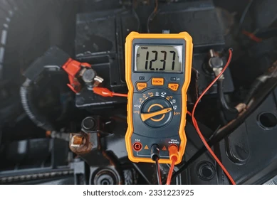
Measuring Available Voltage
20V position on the meter. Connect the negative meter lead to the battery's negative post, then connect the positive meter lead to the battery's positive post. The well-charged battery should read 12.6 V. A meter reading below 11.5 V indicates that the power may not be significant. This determines the available voltage and should be the first step in any electrical troubleshooting procedure.

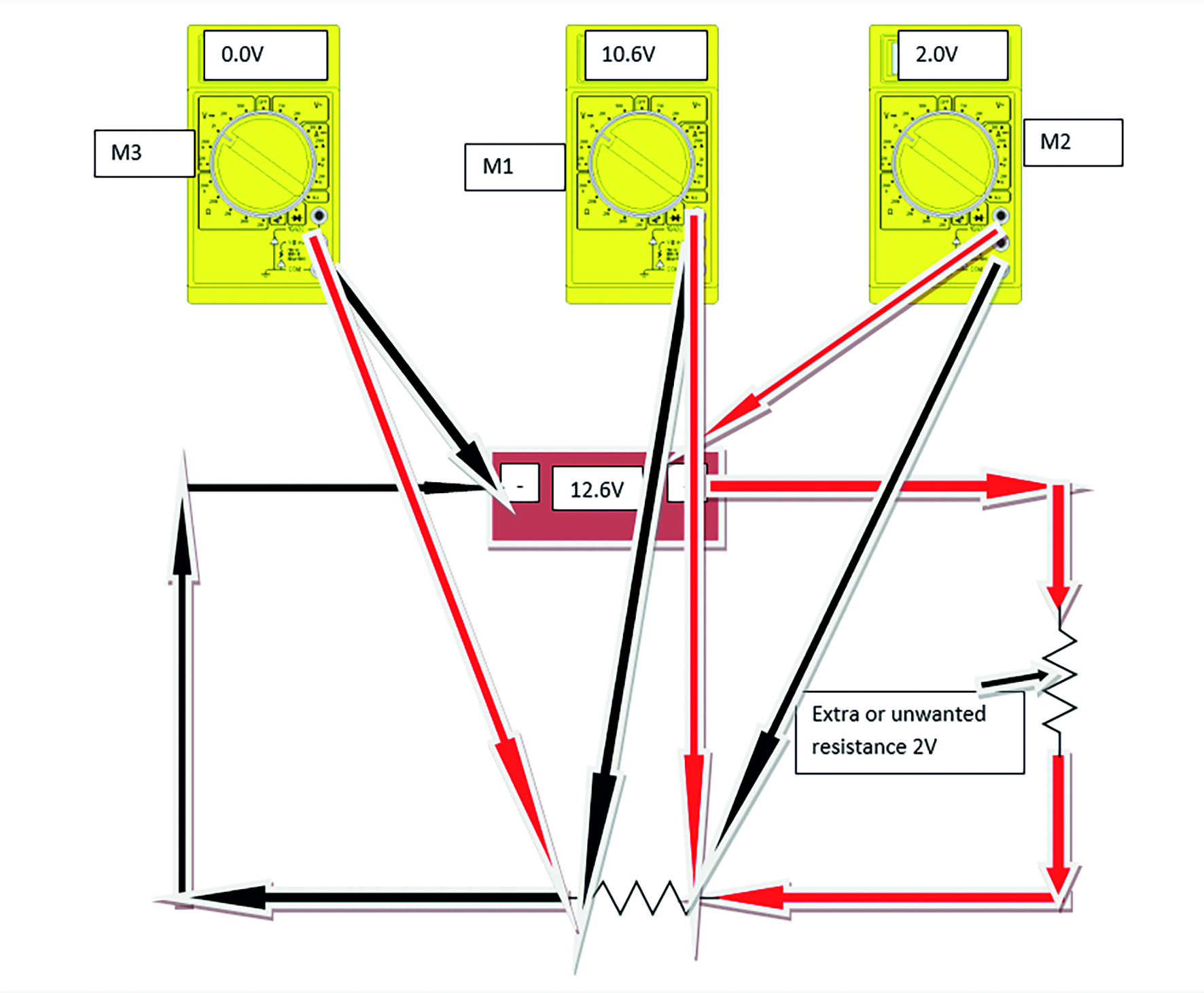
Measuring Voltage Drop
to find unwanted resistance in a circuit by measuring voltage loss across components or wires while the circuit is under load, typically by placing probes on either side of a component and looking for readings above a few tenths of a volt (e.g., <0.2V is good) to identify corrosion, loose connections, or undersized wiring that impedes current flow.

Perform Voltage drop test
Performing a voltage drop test. The circuit must be on, and the meter must be on voltage. Start by connecting the negative lead to the negative terminal of the battery. Now connect the positive lead to the negative side of the load. The voltage should read 0 V. If the reading is above .05 V, it indicates unwanted resistance between the two points. You can also do this on the positive end of the battery. Put the positive lead of the meter on the positive terminal of the battery, then put the negative lead on the positive side of the load. It should read 0 V. If it's above .05 V, there's an unwanted source of resistance. Then read across the load, with the positive lead of your meter connected to the positive side of the load and the negative lead to the negative side of the load. This should read the source voltage in this circuit. It should read 12.6, the battery voltage.

Ammeter
An electrical instrument that measures electric current, the flow of charge, in amperes (A), and is always connected in series with the circuit part being measured, requiring low resistance to avoid affecting the circuit.
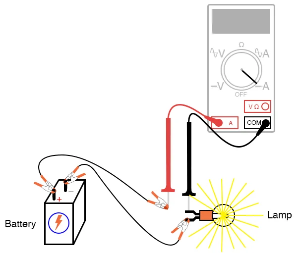
Measuring current (A)
Current tests can be performed anywhere in the circuit using an ammeter, provided the ammeter can handle the current. Both low and high currents can be measured using an appropriate inductive ‘amp clamp,’ which senses magnetic fields around a live conductor and feeds the signal to a meter. The clamp is polarity-sensitive, so observe the current flow direction when placing it; otherwise, the meter may read backwards. Remember Ohm’s Law: higher than normal current indicates lower circuit resistance, while lower current indicates higher resistance.
Ohmmeter
An instrument used to measure electrical resistance (in ohms) of a component or isolated part of a circuit. It can also function as a continuity tester in a non-energized (power-off) circuit. The ohmmeter supplies a small internal voltage and measures the resulting current that flows through the component under test. Since the meter knows its own internal voltage and resistance, it calculates the resistance of the component based on the measured current.
Ohmmeter testing
A digital ohmmeter measures resistance and continuity in a non-powered (dead) circuit using its own internal voltage. Always verify zero by touching the leads together before testing, and isolate the circuit from power to prevent meter damage. Either lead can be connected to any test point.
Continuity: Zero or low resistance indicates continuity; infinite resistance indicates an open.
Shorts to ground: Zero resistance indicates a short; infinite resistance indicates no short (circuit must be isolated from power and ground).
High resistance where none is expected indicates a fault.
Ohmmeter testing is a static test and may not reveal faults under load; voltage drop testing is preferred for operating circuits. Isolate at least one side of the circuit to avoid parallel resistance, which lowers readings. Use the correct ohm scale and compare component readings to OEM specifications.
For computer-controlled systems, use a digital ohmmeter with at least 10 MΩ input impedance to avoid damage to electronics.
Backprobing/Piercing
Backprobing or wire piercing is used to check power or take measurements in a circuit without disconnecting the connector. Backprobing is done by carefully inserting a thin pin or stiff wire into the rear of the connector to make contact. Use caution to avoid damaging terminals or wire insulation.
Any pierced wire must be sealed after testing with liquid electrical tape or clear nail polish to prevent moisture and corrosion. Never use silicone as a sealing agent.
Safety note: In tight or hard-to-reach areas, use insulated boots on jumper wires and backprobe pins to prevent accidental grounding, sparks, or fire—especially when testing fuel system components.
jumper wires
Jumper wires are used to bypass sections of a circuit to help locate electrical faults. They are typically made from multi-strand wire with alligator clips or appropriate connectors on each end. Always use a fuse-protected jumper wire to prevent damage to the vehicle’s wiring.
Jumper wires are mainly used to find open circuits on either the ground (–) or power (+) side.
If a component operates when jumpered to a good ground, the ground circuit is open.
If the ground is good and the component still does not operate, the power feed to the component is open.
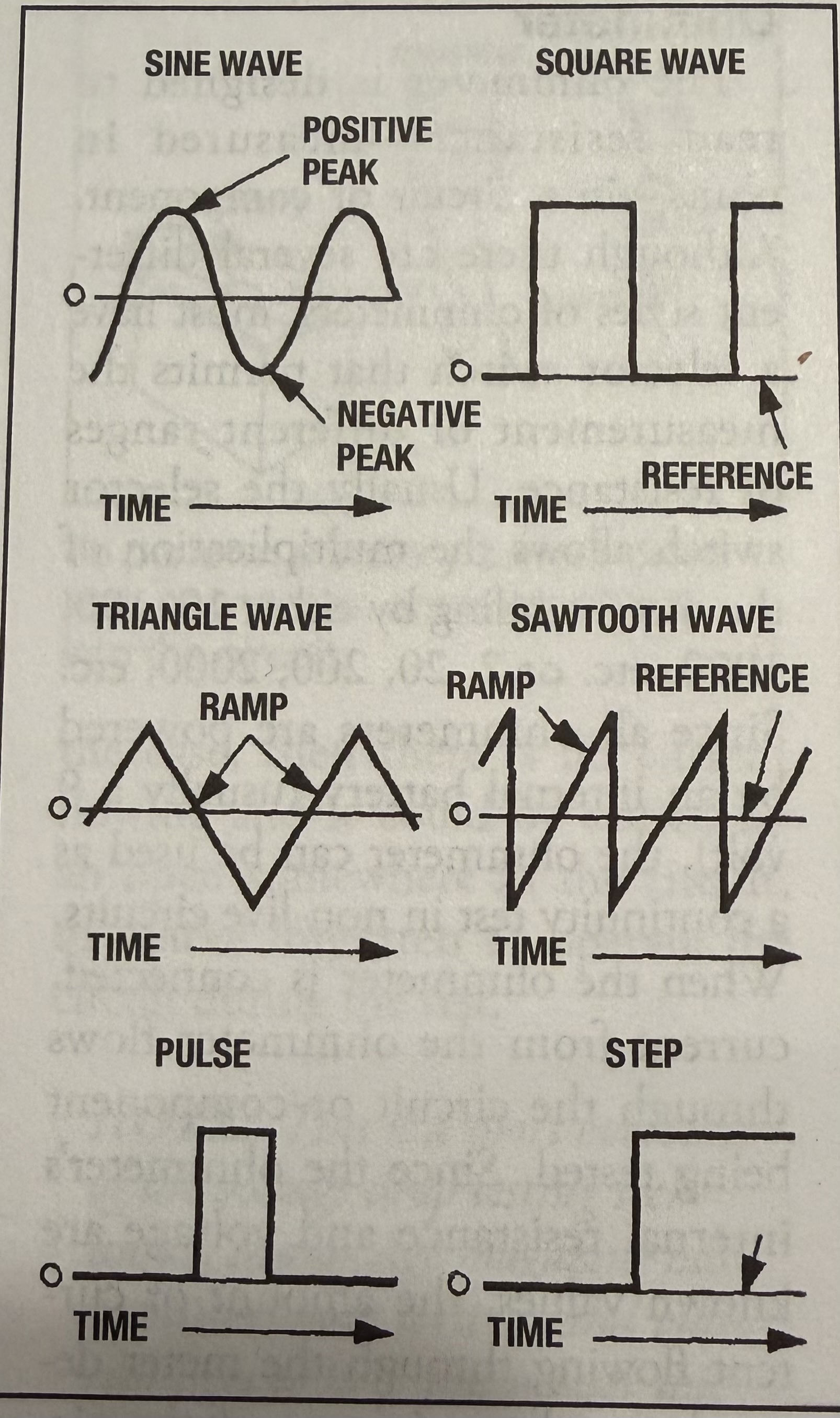
Oscilloscope
An oscilloscope displays a real-time waveform of an electrical signal (usually voltage) showing how it changes over time. Automotive oscilloscopes operate over time ranges from microseconds to over one second. By comparing waveforms to known-good patterns, technicians can identify circuit or component faults.
Oscilloscopes are especially useful for diagnosing intermittent problems that voltmeters may miss, such as faults in TPS, MAP, or MAF sensors. Unlike analog or digital voltmeters, which show average or sampled values, an oscilloscope reveals momentary voltage changes caused by intermittent opens or shorts.
There are two main types:
Live analog oscilloscopes, which require the signal to be present and repetitive
Digital Storage Oscilloscopes (DSOs), which sample, store, and reconstruct signals for later viewing

scope display
An oscilloscope displays voltage or current versus time, with the vertical axis showing signal value and the horizontal axis showing time. Scale, triggering, and sweep settings control how the waveform appears, and many scopes offer auto-set and multi-trace features for quick setup and signal comparison.
Determining an interpreting readings on a Osilloscope
A Digital Storage Oscilloscope (DSO) functions like a voltmeter that graphs voltage over time, making it ideal for detecting fast or intermittent faults that a Digital Multimeter (DMM) may miss, such as momentary signal loss from a Throttle Position Sensor(TPS). By comparing scope patterns to known-good waveforms, technicians can identify problems. Always interpret the waveform as you would meter readings by checking voltage range, irregularities, and signal ground quality.
Scan Tools
A scan tool connects to a vehicle’s Data Link Connector (DLC) to communicate with onboard computers. It is used to read diagnostic trouble codes (DTCs), view and graph live data Parameter Identifiers (PIDs), record snapshot data, and perform system tests. Modern scan tools help technicians quickly identify failed components, wiring faults, or module-related issues.
OBD-II DTCs use a standardized format (B, C, P, U) with generic (SAE) and manufacturer-specific codes. Scan tools may be OEM or aftermarket, handheld or PC-based, and often support bidirectional control, allowing components and actuators to be commanded for testing.
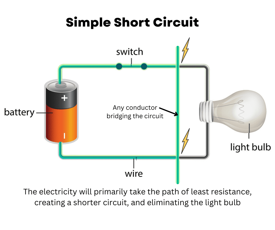
Short Circuits
There are two types of short circuits: short to power and short to ground. A short to power may occur inside a component or between circuits, causing improper or unintended operation; low resistance readings indicate an internal short. A short to ground usually blows a fuse, though if it occurs on the ground side before a switch, the component may stay on without blowing the fuse.
Shorts are diagnosed using voltmeters, circuit probes, or a short finder, which replaces the fuse and uses a pulsing magnetic field to locate the short by tracking where the signal stops.
Finding Short Circuits
Some blown fuses are caused by intermittent or transient shorts that are difficult to reproduce. These may result from worn insulation, moisture intrusion, or wiring rubbing against the vehicle body, causing a temporary short—often appearing only in wet conditions.
Shorts can also be caused by momentary overloads, such as electric motors drawing high current at startup or becoming jammed (for example, frozen wiper or window motors). In circuits with multiple loads on one fuse, a short may not be obvious unless the wiring diagram is checked. Always inspect schematics and consider operating conditions when diagnosing elusive short circuits.

open circuits
An open circuit occurs when current flow is interrupted by a break in a wire, switch, or relay. To repair it, trace the circuit using wiring diagrams and follow the normal current path, testing with a voltmeter to locate and repair the break.
circuit loads
A load device is the component that performs the work in a circuit (lights, motors, horn, etc.). If proper voltage reaches the load and the circuit is not open, shorted, or poorly grounded, the device should operate. Use a voltmeter to check for power and correct voltage drop across the load.
All circuits require a good ground. Loads may be internally or externally grounded, with external grounds becoming more common due to non-metal vehicle panels. Always ensure the ground connection is reattached before powering a replaced component.
Key-Off Battery Drain
Key-off battery drain occurs when excessive current is drawn while the vehicle is off, leading to a dead battery. Normal draw is required to maintain memories (radio presets, PCM data, clock) and is typically 30–50 mA after all modules go to sleep, which may take several hours.
Excessive drain is often caused by faults such as stuck glove box or trunk lights or modules that fail to power down. The best way to test is with an ammeter in series with the negative battery cable or a low-amp clamp meter around the negative cable.
If excessive draw is found, remove fuses one at a time until the current returns to normal, then use wiring diagrams to isolate the faulty circuit. If needed, check circuits protected by fusible links.