Circuits midterm 1
 Call Kai
 Learn
Learn Practice Test
 Spaced Repetition
 Match
Match Flashcards
 Knowt Play
1/49

Earn XP
Description and Tags
equations, concepts, and step by step
Name | Mastery | Learn | Test | Matching | Spaced | Call with Kai | Chat |
|---|
No analytics yet
Send a link to your students to track their progress
50 Terms
KVL Big rule
VLoop = 0V
Conservation of energy
must stay consistent
KVL and KCL voltage and current direction
entering node = +, leaving node= —
Passive convention
if voltage direction is forced , current direction is forced, vice versa
Electrical Resistance - Ohms law on graph
V= IR
V = y axis
I = x axis
R = slope
KCL Big rule
Iloop = 0A
Conservation of charge
must stay consistent
Circuit Analysis
Assign refernce direction
Basic circuit element: Nodes & loops, K laws
check anwer with Power balance
Power balance
total power absorbed + total power delivered = 0
Passive sign convention for power
Power > 0W = absorbed
Power < 0W = Delivered
Ohms law on graph = R linear
Pv = (+)(+)
Pv = (-)(-)
Independent Voltage

Independent Current Source
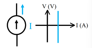
Open circuit for ohms law
current = 0 A
Resistance = infinte
Voltage still present
Open circuit
An open circuit means the electrical loop is incomplete, so no electricity moves through the device.
Short circuit in terms of ohms law
current = infinte
Resistance = 0
Voltage still present
Short circuit
A short circuit happens when electricity skips the intended load (like a light or motor) and takes a shortcut with almost zero resistance.
Voltage and Current divider
a quick way to determine the wanted current or voltage with ohms law, resistance equivalence, and the equation
Vwant = Vtotal (Rwant / REQ)
Current Division Rule
The current division rule applies to parallel circuits where a total current splits among different branches.
Notice that the numerator uses the opposite branch's resistance

Voltage Division Rule
The voltage division rule applies to series circuits where a total supply voltage shares across components
use the same resistance whose voltage you want to find

Dependent Source
Voltage of a current source that is dependent upon a different voltage or current.
Independent Voltage Source
True

Voltage controlling source
True

Voltage dependent source
True

Combined Constraints
Identify elements: voltage and current, passive sign convention
Identify nodes and loops, and write KVL and KCL equations
Solve the system of equations
Element constraints
voltage and current elements, passive sign constraints
Connection Constraints
Identify nodes and loops, and write KVL and KCL equations
Combined Constraints
Solving the KCL and KVL system of equations
Element Equation
Total elements in circuit: voltage and current source, and resistors
KCL equation
total Nodes -1
KVL equations
Elements - N + 1
Total independent equations
Element Equations + KCL equations + KVL equations
Node Voltage analysis
only works with essential node, reference node, ground
essential node
a connection point in an electrical circuit where three or more circuit elements or branches meet

reference node
a single point in an electrical circuit assigned a potential of zero volts (0 V) to serve as a common baseline for measuring all other node voltages. The Vc if you will.
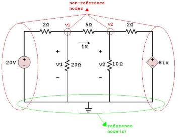
Ground
It gives electric current a safe path to return to its source and complete the circuit.
Steps for Node Voltage Analysis
Select reference node
Highlight & Label Nodes
KCL @ N - M - 1
IR = (Vtail - Varrow )/ R
Solve system of equations
Back-solve to find currents
modified KCL equation

Supernode
Voltage source is not referenced to ground, not directly connected to ground

Writing equations for Supernode
treat nodes connected to floating voltage source as single node. Equations modeled like modified node anaylsis KCL equation
Source transformantion
Convert b/w independent voltage & current sources @ interface. done with ohms law
related to thevenin & norton equivalent circuits
Thevenin & Norton Equivalent Circuits
Modeling used to design interfaces → complex circuits in a simple circuit with only a single independent source, equivalent resistance, and resistor load
Thevenin Equivalent equation
VTH = IL * RTH
Norton resistance
same as thevenin resistance
External Test Source Method Equivalent Resistance
used when there is dependent source in circuit
1. turn of independent source
2. replace load with an external test source
Independent voltage or current, Label VT / IT
Solve for VT / IT = RTH
Norton Equivalent Current
Current as seen by the load → need to short circuit
Thevenin Equivalent Voltage
VTH
Voltage source as seen by the load → Need Open-CIrcuit
Norton equation
VTH = IN * RTH
Maximum Power Transfer
For a fixed source & variable load, it is the maximum possible power delivered to the load
Maximum Power Transfer equation
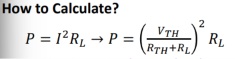
When does Max Power occur
Matched load.
when Rload = RTH

Superposition Principle
For Linear System where Total response of a system is the
sum of the individual responses
How to Apply Superposition?
Turn off the opposite independent source
2. Analyze the circuit with the desired method.
When all parameters are found, sum them for the total.