FG-09 Location and Functions of the AN-APS 504
1/24
There's no tags or description
Looks like no tags are added yet.
Name | Mastery | Learn | Test | Matching | Spaced | Call with Kai | Chat |
|---|
No analytics yet
Send a link to your students to track their progress
25 Terms
AN/APS 504 Components
Antenna
Antenna/yoke/pedestal assembly
Waveguide Pressurization System
Waveguide to Receiver-transmitter
R-T Transmitter section
Syncronizer processor converter unit (SPCU)
Remote radar interface unit (RRIU)
Pilot Control Unit (PCU)
AN/APS 504 Antenna size and shape
42” flat-plate planar array.
AN/APS 504 rotation extent
360° rotation
Pitch, roll, and heading outputs from what are sent to antenna for stabilization.
Inertial Reference Unit (IRU)
AN/APS 504 Antenna/Yoke/Pedestal assembly stabilisation extent and antenna tilt
Stabilized up to 20° for aircraft Pitch and Roll.
Antenna Tilt from -16° to +16°
Waveguide pressurization system
Pressurized system containing nitrogen.
Maintains waveguide system at a constant pressure and humidity to prevent arcing within the waveguides at high altitudes.
Waveguide pressurization system location and components and maximum bottle pressure
Located in the radome.
High-pressure nitrogen bottle w/ gauge.
Regulator that drops bottle pressure to a maximum of 20 psi w/ output gauge.
R-T Transmitter section
modulator,
thyratron,
magnetron,
trigger amplifier,
control circuitry.
Magnetron
produces a burst of RF energy for antenna radiation.
Syncronizer Processor Converter Unit (SPCU)
Overall Radar system Timing & Control (i.e. synchronization) including;
PRF generation
Rx-Tx trigger pulse
Signals to determine operation and display modes
Video/Signal processing
Radar Scan Conversion
Remote Radar Interface Unit (RRIU)
Interfaces the Radar with the NTS to allow radar operation via the NTS Radar CDU Panel.
Interfaces the Radar with the PCU allowing pilot-control of the radar when NTS is not selected.
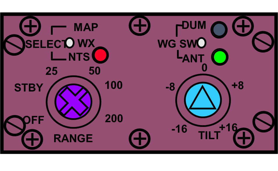
Pilot Control Unit (PCU)
Located between the pilot and co-pilot, the PCU provides the pilot with four controls: a select switch, waveguide switch, tilt control, and range control. The three-position select switch allows selection between WX (weather) and MAP functions and transfers control of the radar to the TMT Server computer. The waveguide switch selects between transmitter and dummy load. The tilt selector controls antenna tilt between -16 and +16 degrees when the TMT Server computer is not selected. The range control provides system power-off and standby capability, and selects radar operating ranges from 25 to 200 Nm.
Operator Interface Warning
DO NOT OPERATE THE RADAR ON THE GROUND UNLESS THE WAVEGUIDE SWITCH ON THE PCU IS SELECTED TO DUM (DUMMY LOAD)
DO NOT SELECT RADAR TO TRANSMIT IF PERSONNEL ARE WITHIN 100 FEET IN THE 360° SCAN AREA, OR IF REFUELLING IS BEING CARRIED OUT ON OR NEAR THE AIRCRAFT (WITHIN 100 FEET)
Search RADAR Frequency
9375 MHz
Transmitter peak power output
100 kW
RADAR Search Ranges
3
6
12
25
50 NP
50 WP
100
200
3nm PW and PRF
0.5 microseconds
1638 pps
6nm PW and PRF
0.5 microseconds
1638 pps
12nm PW and PRF
0.5 microseconds
1638 pps
25 nm PW and PRF
0.5 microseconds
1638 pps
50nm NP PW and PRF
0.5 microseconds
910 pps
50nm WP PW and PRF
2.4 microseconds
364 pps
100nm PW and PRF
2.4 microseconds
364 pps
200nm PW and PRF
2.4 microseconds
212 pps
Scan rates at each range scale
3, 6, 12, 25, 50 NP - 30 rpm
50 WP, 100 - 12 rpm
200 - 7.5 rpm