turbines 4
1/33
There's no tags or description
Looks like no tags are added yet.
Name | Mastery | Learn | Test | Matching | Spaced | Call with Kai |
|---|
No analytics yet
Send a link to your students to track their progress
34 Terms
combustion chamber purpose
converts potential energy into kinetic energy
an effective combustion chamber must provide
Means for mixing fuel and air for efficient combustion
Burn the mixture efficiently
Provide sufficient cooling to a temperature tolerable by turbine blades under all operating conditions
Distribute hot gasses evenly to the turbine section
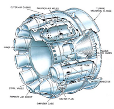
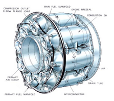
components of combustion chamber
casing
perforated inner liner
fuel drain system
fuel nozzle fuel injection system
igniter plugs
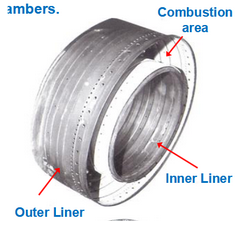
casing
delivers high pressure air to inner liner
provides cooling
perforated inner liner
where fuel/air mixture burns
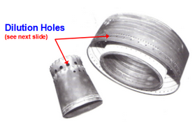
contains holes for air to enter for combustion and cooling
fuel drain system
located at lowest part of combustion chamber
draining fuel prevents tailpipe fires and hot starts during next engine start
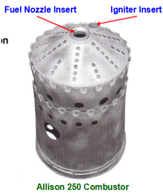
fuel nozzle
inject atomized fuel into the inner liner for combustion
igniter plugs
provide initial ignition
primary air
combustion air
directed into front of the inner liner to mix with fuel for combustion
secondary air
cooling air
passes through outer casing via holes in the liner to prevent combustion gasses from contacting inside wall of inner liner
louvers and cooling holes
directs cooling air along the inside wall of the liner and into combustion air
pre-swirl vanes
installed around fuel nozzles to swirl the incoming air to reduce velocity for combustion and swirl fuel spray
flameout causes
High or slow airflow rates
Turbulent weather
High altitude
Slow acceleration
High speed manoeuvers
types of flameout
lean die out
rich blowout
lean die out
occurs at high altitude, low engine speeds or low fuel pressure
rich blowout
Caused by rapid acceleration with overly rich mixture and insufficient airflow or low fuel temperature
types of combustion chambers
Single-can burner
Multiple-can
Annual combustor
Straight flow
Reverse flow
Can-annular combustor
single can burner
single fuel injection annular-type combustion can
multiple can burner
Consists of series of individual combustor cans that function as an individual unit (8-10 cans)
Cans are interconnected with flame propagation tubes > provide path to spread combustion
annular combustor
Consists of 360 degrees single circular combustor with a basket
straight flow annular combustor
air enters front (fuel nozzle area) and discharged at rear
reverse flow annular combustor
airflow reverses 180 degrees twice
helicopter and turboprop
can-annular combustor
Individual units are arranged radially around the axis of the engine
Cans are connected via interconnect tubes (flame propagation tubes) that move combustion to all cans
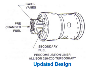
precombustor chamber
Portion of primary air enters precombustion chamber > air is mixed with fuel and ignited > gas enters main chamber and joins primary air and a 2nd fuel nozzle
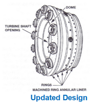
machined ring annular liner
Constructed by welding rings of heavy gauge metal together
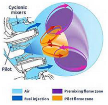
TAPS
Twin Annular Premixing Swirler Combustor Nozzle
Improves fuel efficiency and reduce nitrogen dioxide and nitric oxide emissions
contains 2 independently controlled annular flames for low power (pilot) and high power (cyclone)
TAPS
machined ring annular liner
precombustor chamber
can-annular
annular
multiple can
single can
louvers and cooling holes