Steel Test 2 - CVEN 659
1/178
There's no tags or description
Looks like no tags are added yet.
Name | Mastery | Learn | Test | Matching | Spaced |
|---|
No study sessions yet.
179 Terms
tension field action (TFA)
additional shear strength gained by considering post-buckling strength of web plate that occur from formation of tension field bw transverse stiffeners
not valid at end panels, so stiffeners closer together
max limit of a/h <= 3 to consider TFA
Transverse stiffeners
add stiffness to web plate of beam
transverse relative to longitudinal axis of beam (perpendicular to flange)
resist compressive force that will develop when web plate buckles in shear and TFA occurs
slenderness is limited to prevent local buckling
adding stiffeners cheaper than thickening web of main member
welded plates most common but can do bolted or welded angles
termination: welded, tight-fit, cut short
what properties important for steel
tension more important than compression
buckling limiting state for compression and controlled by geometrical conditions
heated at low temps: blue color (600F) →dark red→ cherry red → orange-red-yellow→ white (2500F)
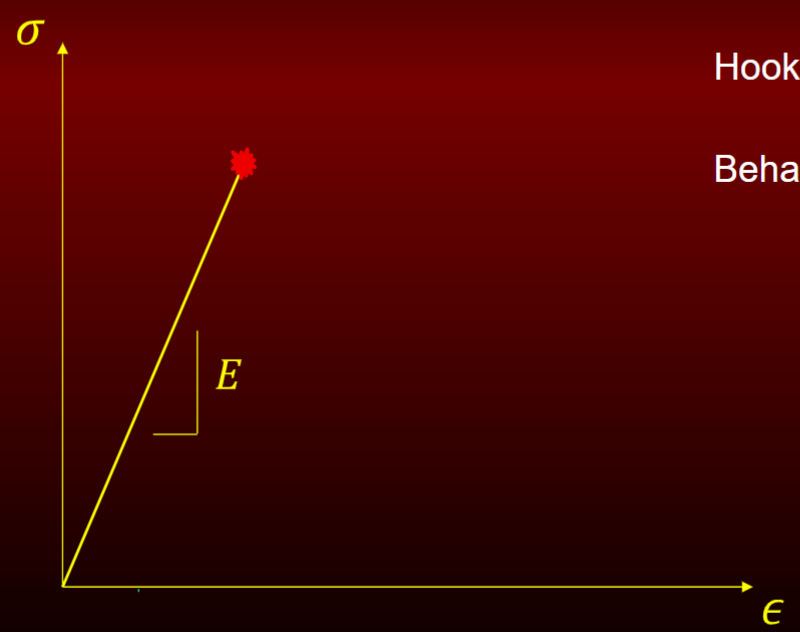
Elastic response
hooke’s law
behavior of glass
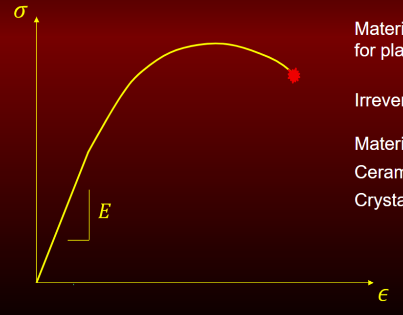
elastic-homogenous plastic response
has capacity for plastic deformation
irreversible plastic flow (can see in high strength steel)
materials: ceramics, crystalline polymers
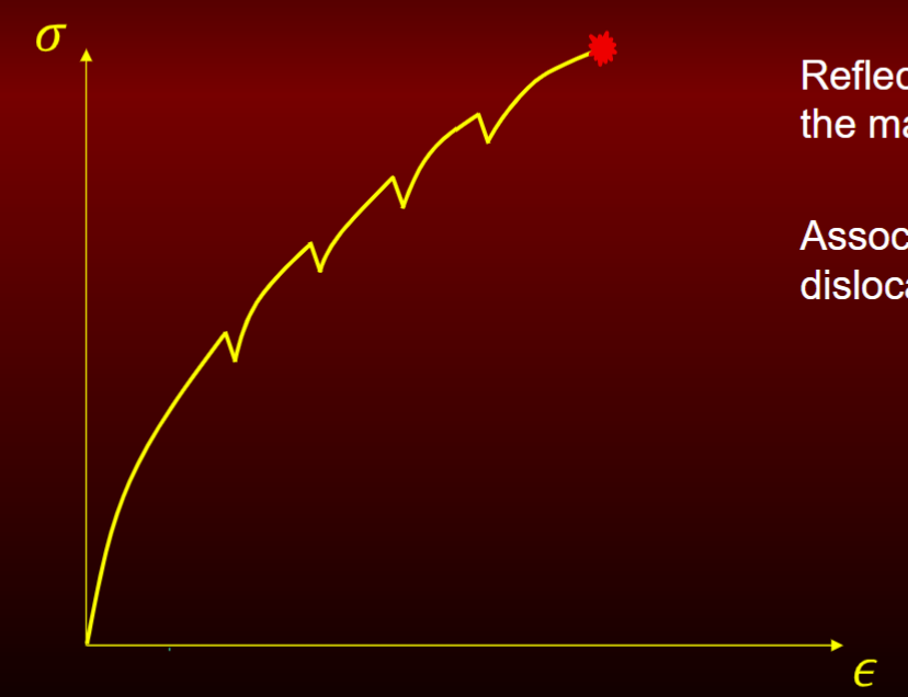
Elastic heterogenous plastic response
reflects non-uniformity of the material
associated w atomic dislocation interaction
very small portion
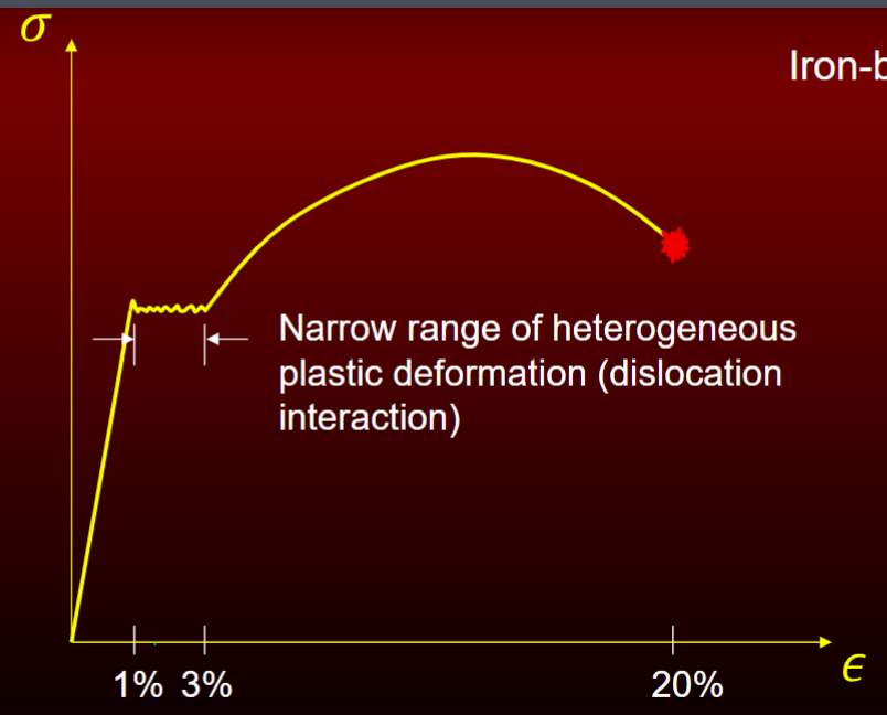
Elastic Heterogenous Plastic Homogenous Plastic
ex. iron based alloys (BCC)
include strain hardening and smaller squiggle = more alloyed
narrow range of heterogeneous plastic deformation (dislocation interaction)
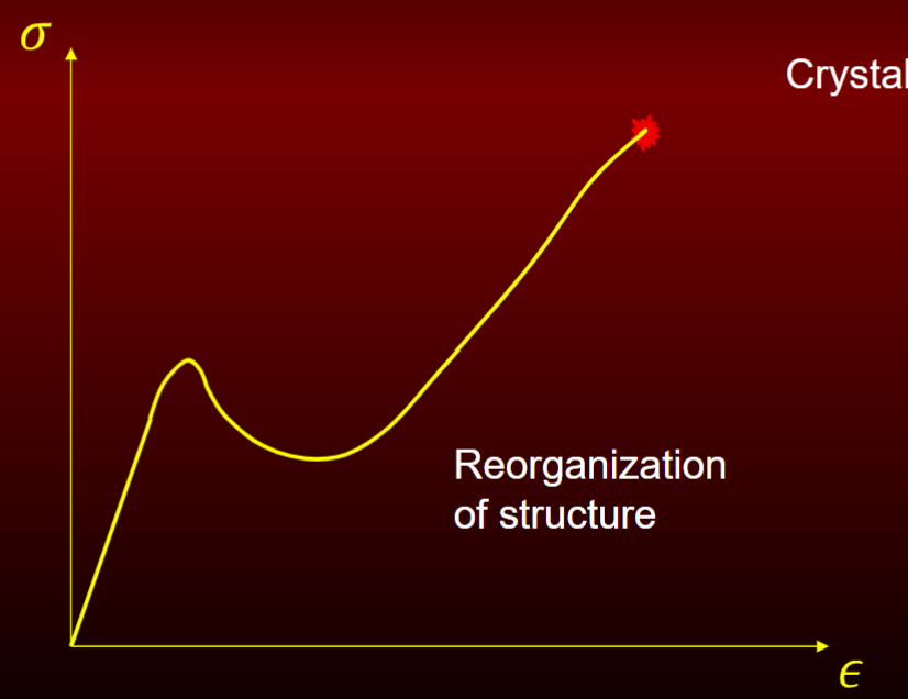
Elastic plastic homogenous plastic response
ex. crystalline polymers (chains of mlc)
reorganization of structure = gain strength similar to post buckling
Theoretical strength of material
based on atomic bonding forces is always much higher than experimentally observed
bc presence of defects
point defect
atomic lattice is missing a single atom
have minimal effect on strength
vacancy may be occupied by alloy
line defect
defect is a line in the 3rd dimension and is a dislocation
under shear stress, atomic bonds around dislocation will break and reform consecutively allowing dislocation to move
dislocation stops at free surface or at grain boundary
if restrict dislocation movement, decrease ductility
alloy atoms bond with metal lattice if not alloy becomes impurity and strength is lowered
metallic bond
element have only 1/2/3 valence electrons and are bonded loosely to nucleus
as atoms come together, create electron gas
electrons try to repel each other but attraction to nucleus is greater
leads to good ductility and electrical conductivity
ductility
achieved as one plane of atoms slide over another plane without fracturing as atomic forces easily reach new equilibrium
Basic phases of steel that are 0.20% carbon
austensite
ferrite
cementite
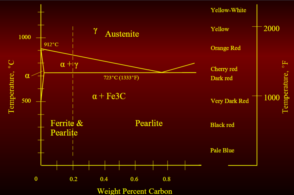
austensite phaes (gamma iron)
iron w moderate solubility for carbon having a face centered cubic (FCC) structure
hot rolling structural shape and plate done at this temp range (1230-2250 F)
soft and has low modulus which reduces forces required to form and roll
Ferrite Phase (alpha iron)
iron w lower solubility for carbon with a body centered cubic (BCC) structure
low strength but high ductility
Cementite Phase (alpha + Carbide)
hard and brittle phase with high solubility for carbon
high strength but low ductility
Martensite
very brittle phase that can form if steel is heated above the austensite transformation temp and then it’s temp is quickly reduced (via quenced)
oxidation of steel
oxidation is an indicator of max temp
oxidation forms above 1200 F
Body Centered Cubic (BCC)
32% voids
Iron to 910 C and above 1400C to melting at 1538 C(2800F)
Carbon barely fits in the interstitial sites
carbon can be squeezed out if cool slowly
cool fast allow carbon get trapped = brittle bc strain from tensile
Face Centered Cubic (FCC)
26% voids
Iron (Fe) between 910 C to 1400 C
Cannonball stacking
most efficient, high ductility
more carbon allowed in structure
interstitial spacing is larger
100x more carbon can be dissolved here
Interstitials
small non-metallic atoms that located in vacant spaces bw metal atoms
larger than the free space but easily fit into interstitial sites
as metal cools, interstitials force iron atoms apart and creating strain
when FCC cools down to BCC, higher internal lattice strains
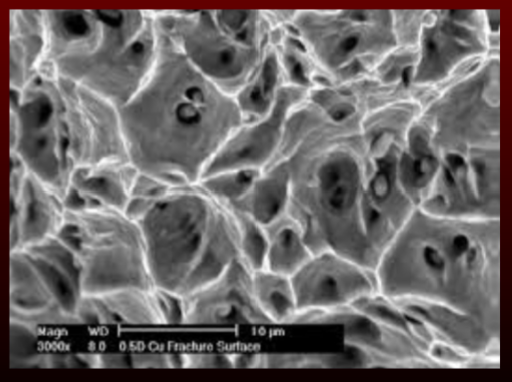
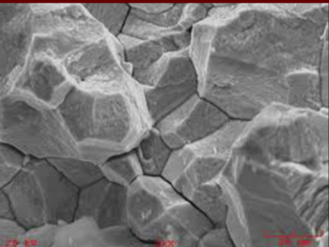
microscopic fracture/rupture mechanism
microvoid coalescence - give higher strength (want)
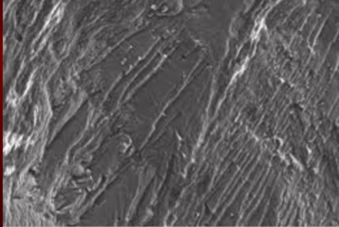
cleavage/transcrystalline - shear
intergranular fracture - don’t want bc rupture path bw grain
microvoid coalescence
initiated by nucleation of microvoid at inclusions or precipitate particles and surrounding lattice
as indv microvoids grow, begin to coalesce into larger cracks/seperation planes
high strength rupture
cleavage/transcrystalline
rupture along specific crystallographic planes
rupture path travels through grains
moderate strength
occur due to shear failure
Intergranular Fracture
brittle fracture where crack prefers to follow grain boundaries rather than through lattice structure or indv grains
characteristic of low fracture toughness
low strength fracture
Properties of steel and carbon content
Pure iron Fu = 4 ksi
w 0.2% carbon by wt Fu = 60 ksi
w 0.8% by wt Fu = 110 ksi
construction steel have carbon content bw 0.15 - 0.25% by wt
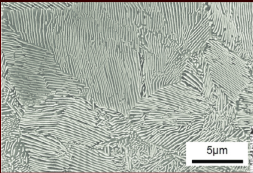
Pearlite
lamellar structure made of ferrite and carbide
Martensite Formation
if autensite cooled rapidly (quenching), diffusion of carbon prevented
trapped carbon in BCC cause lattice to distort into BCT (body centered tetrahedral)
non-symmetrical distortion causes internal strains that react strongly and lock dislocations reducing ductility
higher the carbon content, martensite formation occur at lower cooling rate → welding difficult
Tempered Martensite
brittleness of martensite can be minimized by reheating to some temp below 1350F (DO NOT RETURN TO AUSTENSITE PHASE)
carbon diffuses from solid solution into particles of cementite
tempering temp and a little time determine degree of martensite transformed into cementite
holding temp range from 800F-1200F
Annealing
Purpose: to soften
procedure: heated back up to above Austenite transformation line and cooling slowly
Steel strengthening mechanisms
chemistry - alloying
heat treating
fine-grain practice
alloying
solute atoms occupy dislocations restricting their movement, increasing strength, but reducing ductility
Aluminum alloying effect
deoxidizer, improves grain structure (removes O so Fe can bond w C)
Carbon alloying effect
improves strength and hardness at expense of ductility and toughess
low carbon: <0.3%
medium carbon: 0.3% - 0.5%
high carbon: 0.5% - 2%
cast iron: >2%
Chromium alloying effect
improves strength, hardness, corrosion resistance, and retention of strength at high temp
Copper alloying effect
improves corrosion resistance (A588) discover by accident
weather steel: corrosion product adhere to base metal and create protective layer
Niobium alloying effect
greatly improves strength
Manganese alloying effect
widely used to offset effects of sulfur
improves capability to be rolled
decreases ductility
improve capability to receive heat treatment
Molybdenum alloying effect
improves strength at high temps too
corrosion resistant
resistance to creep
Nickel alloying effect
w chromium, used to make stainless steel
improves toughness and impact strength
Phosphorus alloying effect
improves strength and machinability
reduces ductility
Silicon alloying effect
used in relatively large amount (25%) as an oxidizing agent
detrimental to steel if remains in small quantities
Vanadium alloying effect
improves grain structure
increases toughness and impact resistance
oxygen alloying effect
embrittles steel
upset atomic bonding
Sulfur alloying effect
reduces strength at elevated temperature
reduces toughness
improves machinability
comes from coal when burning for carbon
iron sulfide low melting/freezing points so it freezes after austenie phase of steel and will segregate grain boundaries
Hydrogen alloying effect
interferes with atomic bonding bw iron and carbon mlc
impurities
oxygen
sulfur
hydrogen
as steel solidifes, grain grow together and bond; impurities make it hard
Alloy Cleanliness
high quality steels achieved by melting in a vacuum bc reduces amount of inclusion and trapped gases
sulfur impurity major concern bc can form a film along grain boundaries
welding FeS is detrimental
can minimize FeS by adding Mn
Mn forms with FeS → MnS at higher temps so will have small spherical inclusions instead
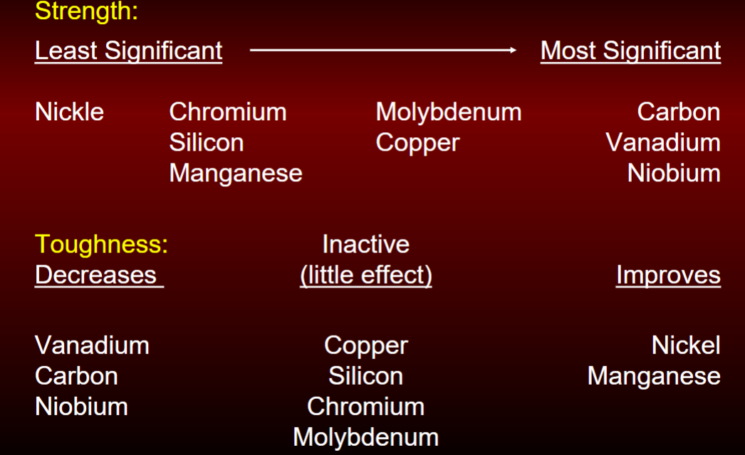
Alloy effect on strength vs toughness
look at image
heat treatment of steels
max yield strength through alloying is 75 ksi
high strength steels obtained by heat treating
done to enhance desired properties of steel
performed on rolled plate not shapes
Normalizing
purpose: to produce a uniform, fine-graded microstructure
procedure: air cooled form austensite stable range
quenching
purpose: to harden
procedure: rapid cooling from austensite to form martensite (strong but brittle)
tempering
purpose: to toughen
procedure: reheat martensite to form tempered martensite
austempering
purpose: to harden
procedure: quench, followed by isothermal transformation above martensite to form bainite
quenching and tempered process
plate put in furance at temp above austenite temp and then removed when reach uniform temp
plate immediately water-quenched to form martensite
plate is tempered in furnace to form tempered martensite
plate air-cooled after removed from tempering furnace
similar to high strength bolts
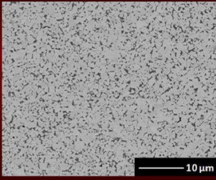
fine grain practice
process which final steel has smaller grain size than normal
increases strength of steel as it prevents impurities from segregating to few grain boundaries
impurities more widely dispersed and can’t accumulate in great quantities
Al typically used to achieve fine grain microstructure with Nb and V
steel solidification process
killed
semi-killed
rimmed
Killed
steel completely deoxidized
done by addition of an agent before casting so no evolution of gas during solidification but shrinkage occurs
high degree of chemical homogeneity and free from gas porosity
steel will quietly solidify in the mold w no gas bubbling out (get its name)
continuously casted steels are always killed
semi-killed
mostly deoxidized
carbon monoxide leave blowhole type porosity
when hot-rolled, porosities are closed
evolution of gas tends to partial compensate for shrinkage that occurs during solidification
Rimmed
little or no deoxidizing agent added
causes carbon monoxide to evolve rapidly resulting in small blowholes on surface which will close during hot rolling
elements like C, P, S segregate to center leaving almost pure iron at rim
Steel making process: Blast furnace
process used to convert iron ore into liquid iron and is unfinished steel
iron ore, coke, limestone fed into top of blast furnace and preheated air is blown up from bottom
takes 6-8 hours for raw materials to descent to bottom of furance where become final product of liquid iron and liquid slag
continuous process: raw material fed at top and liquid iron tapped from bottom
Steel making process: Basic Oxygen Furnace
70-80% liquid steel from blast furnace w balance being scrap steel
liquid hot metal and scrap are charged w near pure oxygen which is blown into the mix at supersonic velocities
oxidizes carbon and silicon contained in hot metal which liberates great quantities of heat, which melts the scrap
after sample taken and analyzed for its chemical composition, carbon and other alloying elements added
Steel making process: Electric Arc Furnace
can use 100% scrap steel but often some liquid steel left from previous run
graphite electrodes used to produce voltage differential which melts steel scrap
when scrap is molten, oxygen fed into liquid bath to oxidize P, S, Al, Si, Mn, and C
after sample is taken and analyzed, carbon and other alloying elements added
Mill Report
steel resulting from once cycle from basic oxygen furnace or electric arc furnace is called Heat
each heat analyzed for its chemical composition and mechanical properties
results in mill report
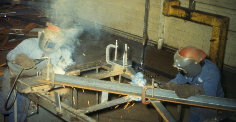
def weld
localized coalescence of metals or nonmetals produced by heating the material to suitable temps w/ or w/o application of pressure and filler metal
welding process - steel
oxyfuel gas - not used a lot
electric arc
friction - small length
resistance - automobile industry, press together to weld
casting - rails in railroads
electric arc welding
shielded metal arc welding (SMAW)
flux cored arc welding (FCAW)
gas metal arc welding (GMAW)/MIG
Gas Tungsten Arc Welding (GTAW)
Submerged Arc Welding (SAW) - automated
arc welding components
power source (modifies and controls input electrical current)
electrode (consumable or non-consumable)
shielding (gas or solid that forms gas as it burns)
Electrical Current
W = V x A
wattage - measure of work (controls width and depth of weld bead)
voltage - measure electrical pressure (controls max length of arc across gap)
amperage - measure of rate of flow of electron (controls arc size)
Types of welding current
AC - alternating current - plug into wall
DCSP: direct current - straight polarity
DCRP: Direct current - reverse polarity
power source either AC or both DCSP and DCRP
Arc temperature
Approx 9000 F - HOT
affected by resistance to current flow - want resistance
large gap = large resistance which increase temp
Resistance
function of arc length and chemical composition of gases formed or introduced during welding process
Arc stabilization
important that current flow stable so that uniform and consistent weld is formed
modern day power supplies digitally controlled
shielding gases used to stabilize arc in addition to protecting weld pool from atmosphere (protect from O)
Straight Polarity DCSP
electrode negative (DCEN) - greater penetration
more heat at base plate
electrode negative contains 1/3 heat
base plate positive contains 2/3 heat
flow from negative to positive
Reverse Polarity (DCSP)
more heat at electrode (greater deposition)
electrode positive contains 2/3 heat
base plate negative contains 1/3 heat
this is faster bc depositing weld metal onto base plate faster
Arc Blow
deflection of an electric arc from its normal path bc of magnetic forces
uneven flux lines can cause arc to move during weld
more noticeable in corners, at end plates, when work lead is connected to only one side of plate
not a problem w AC current
Fillet Welds
simplest and least expensive
prefered
weld produced by depositing weld metal at corner formed by intersecting or lapping plates
Complete Joint Penetration Groove Weld (CJP)
used in application were maximum strength of connection is required
weld produced by cutting or grinding chamfer or bevel on edge of plate
no stress calc involved for weld
usually do fillet weld at end bc shear flow
Partial Joint Penetration Groove Welds (PJP)
similar to CJP where plate edges are beveled prior to welding
finished weld doesn’t fully penetrate plate thickness due to reduced strength requirement
problem in tension bc lack of fusion and can behave like crack
Plug and Slot Welds
connect lapped plates
plut or slot cut into one of the plates
plates are then lapped and hole filled with weld metal
SMAW
on drawing specifiy electrode strength
FCAW and GMAW
use same eqiuipment
FCAW - flux-core hollow wire can automate but hard to clean up; no additional shielding gas required
GMAW - solid wire pump use w gas
Welding Parameters
current (volts/amps)
travel wire speed
electrode (solid or flux-cored)
shielding gas
Shielding Gas
Ar - stable arc, high density gas envelope, difficult to disturb but expensive
CO2 - less expensive but less dense; great heat conductivity - allow arc burn hotter
Mix - compromise in density and heat conductivity
He - result in unstable arc, low density gas envelope; expensive
MIG Solid Wire Welding
must be used w CO2 or mix
CO2: economical and results in deeper penetration
mix: less splatter and better bead appearance
Indoor use, no wind
can weld relatively thin material (22 gauge)
MIG Flux-Core Wire Welding
no sheidling gas required provide as flux in the core
can use outdoors in windy conditions
good w dirty, rusted, painted materials
Runs hotter than solid wire, limited to 18 gauge or thicker
Mig Power Supply
AC input current converted to DC using rectifiers
rectifier - allows current to flow in one direction
heat generated and lost in rectifiers making DC less efficient than AC
transformer used to step-down voltage of input current and increase amp
input current is 230V and 26A
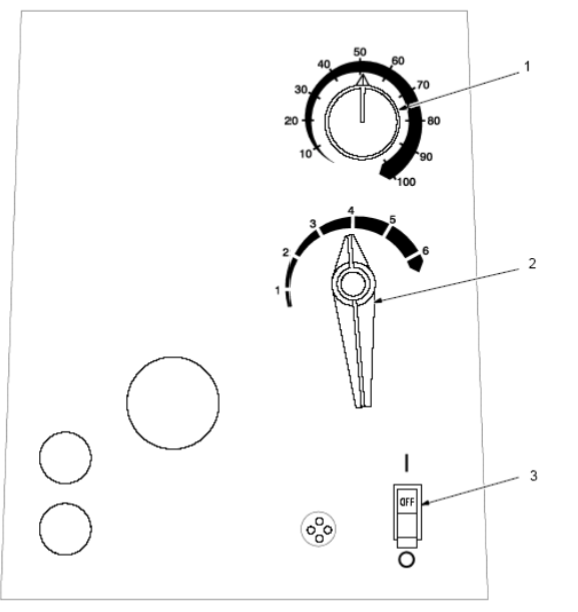
Millermatic 185 Control Panel
wire speed control - can switch while welding
Voltage switch TAP - DO NOT switch while welding; higher number for thicker material
Power Switch
Poor Weld Bead Characteristic
large spatter deposits
rough uneven bead
slight crater during welding
bad overlap
poor penetration
Good Weld Bead Characteristic
fine spatter
uniform bead
moderate crater during welding
no overlap
good penetration into base metal
weld new bead/layer for each 1/8 in thickness in metal
Possible Troubles welding
Excessive Splatter
Porosity
Excessive Penetration
Lack of Penetration
Incomplete Fusion
Waviness of Beam
Burn Through
Distortion - can cause residual stresses if clamped
discontinuity
interruption in uniformity of a material
all steels and welds contain discontinuities
Metallurgical discontinuity
slag particles
void
shrinkage cracks
inclusions
quenching cracks
cracked carburized layer
process discontinuity
seams
scratches
dents
weld-related
grinding
cracks
design discontinuity
holes
notches
stress concentrations
fatigue cracks
Metallurgical Considerations
weld metal should be low in gas content and low in oxides to avoid porosity
weld metal will solidify very rapidly and therefore, be fine-grained
base metal adjacent to liquid weld pools will be heated into austenitic state and cool rapidly - happens w thick plates bc large heat absorption so need to keep carbon low
metallurgical zone of weldments
A. Composite Zone
B. Unmixed Zone
C. Partially Melted Zone
D. Heat Affected Zone (HAZ)
E. Unaffected Base Metal - area unaffected by welding process
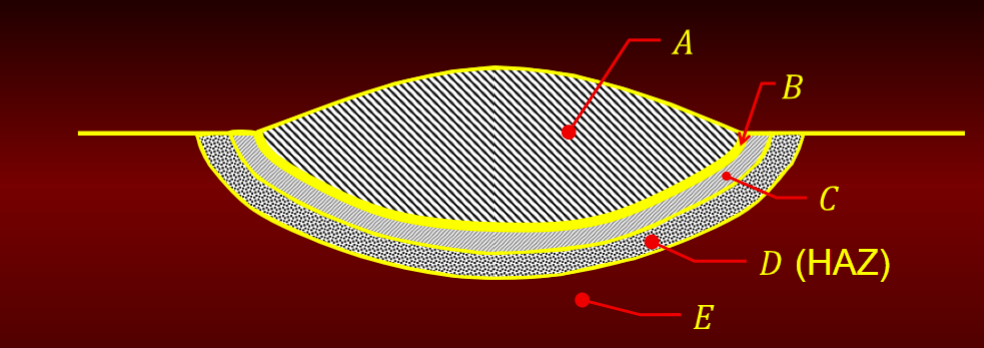
composite zone
admixture of base metal and filler metal
homogeneous with respect to composition
rich chemistry
can contain weld defects such as porosity, blow holes
unmixed zone
boundary layer of melted base metal that wasn’t mixed w filler metal
composition of base metal