MRI
1/38
There's no tags or description
Looks like no tags are added yet.
Name | Mastery | Learn | Test | Matching | Spaced | Call with Kai |
|---|
No analytics yet
Send a link to your students to track their progress
39 Terms
how are magnets made resistant to electrical flow
superconducting
cooled to about 3 K with liquid helium
gradient coils purpose
create a field that’s varying with position along the patient
what is the “banging” noise you hear from an MRI
the gradient coils constantly adjusting their gradients and causing parts to move slightly under the strain, banging around.
common field strengths for MRIs
usually 1.5-3T but constructed 1-9.4 with some smaller (0.35 for Viewray)
magnetic dipoles in the body - common one used for MR and how they align
Atoms that exhibit the strongest magnetic dipoles are ones that have unpaired protons, and the best candidate is hydrogen (one proton) as our body has an endless supply of hydrogen atoms bound up in all the water in our body (other candidates include O, F, Na, K).
Normally the magnetic dipoles of all the hydrogen atoms are oriented randomly in space.
However, in the large magnetic fields of an MRI scanner they align in one of two directions:
They can align with the magnetic field (parallel).
They can align against the magnetic field (antiparallel).
which alignment is preferred for dipoles in MRI
parallel as it is a lower energy state
what is precession and at what frequency is it done
atoms process around the magnetic field
frequency is termed larmor frequency (wo) and depends on the strength of the magnetic field
wo=\gamma B
what is \gamma in the larmour frequency formula
gyromagnetic ratio
42.58 MHz/T for protons (i.e., Hydrogen).
why can we differentiate structures (general principle)
magnetic field varies depending on the tissue of interest (i.e. the chemical environment).
This is extremely important as this is where our contrast comes from.
If all protons responded the same we could not differentiate structures.
what happens if we send an RF pulse into the tissue at larmour frequency
protons will excite and flip to the antiparallel state. This change is exploited for creating image
slice selection in the basic spin echo sequence
turn on a gradient in the z-direction along the bore of the magnet.
By knowing the gradient, we can excite a specific slice by sending in an RF pulse equal to the Larmor frequency which is modified by the gradient

By changing the bandwidth (frequency range) of the RF pulse or changing the gradient we can change the slice thickness.
Frequently, small gaps are left between slices to avoid “cross-talk” where the excitation of one slice excites some of the neighboring slice.
phase encoding in basic spin echo sequence
flipping on a temporary gradient in the y-direction for just a moment, we introduce a continuous change in phase in that direction.
By turning on the gradient, their frequencies change (only in the gradient direction), and, depending on the location of the proton in the y-direction, they may precess faster or slower

Once we turn off the gradient all the protons return to precessing at the same speed but they are all in different phases of their precessional orbit
isolating a single voxel basic spin echo sequence
If we turn a gradient on in the x-direction (and leave this one on), we can cause the protons to precess at different frequencies all along the linear selection

how do we measure individual voxels in MR
we do not measure individual voxels but a whole line of them. Then we separate out all the signals received by the receiving coils through the use of the Fourier Transform in k-space.
k-space is an image, but, instead of being spatially mapped (having x and y coordinates), it is frequency mapped with the center holding the low-frequency information and the exterior the high-frequency information.
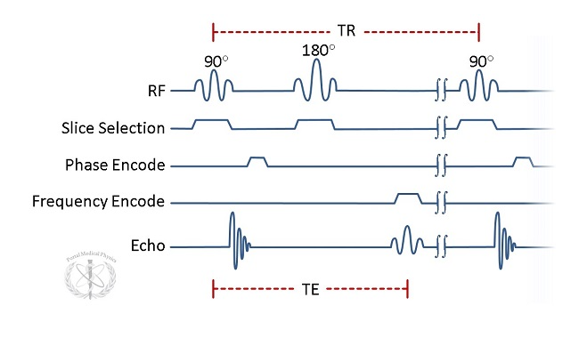
steps of the basic spin echo sequence and draw the pulses
Apply the slice select gradient and transmit RF pulse.
Apply the phase encoding gradient.
Apply the frequency encoding gradient while signal is received.
Fourier transform the received signal.
Repeat steps a-d and average.
Repeat steps a-e with new phase encoding gradients.
Take inverse Fourier-transform of the data from steps a-f.
Repeat a-g with new slice select gradient.
what do we exploit to form an image contrast in MRI
longitudinal and transverse magnetization
atoms return to their ground state the signal decays.
longitudinal magnetization
the number of protons in the antiparallel direction after an exciting pulse.
transverse magnetization
Protons precessing in two states parallel and antiparallel have a horizontal component to their magnetization vector that statistically cancels out if their phases are random (below left) but exists if they are synchronized in phase
Through the use of pulse sequences that flip the direction of precession, the protons can be made to rephase (such as a 180-degree pulse).
Think of a track race. Everyone starts running and the fastest get out in front with the slowest in back. After a time everyone is made to turn around. In the end, everyone will arrive back at the start at the same time since the slowest runners get a head start.
T1 relaxation
longitudinal relaxation (spin-lattice relaxation) which is the time it takes the bulk magnetization to regrow to 63% of its equilibrium value.
occurs when protons realign parallel with the magnetic field causing regrowth of the bulk magnetization vector.
T2 relaxation
transverse relaxation (spin-spin relaxation) which is the time it takes the transverse signal to decay to 37% of its maximum value.
occurs due to local magnetic field inhomogeneities (from the chemical environment) and is a dephasing of the transverse components of the proton dipoles.
what is T2*
the transverse relaxation that actually occurs in your magnetic field due to an imperfect magnetic field being generated
T2* always less than T2
TE
the echo time which is the time between excitation and the measured signal which occurs when the transverse magnetic moments re-phase.
TR
time between the start of a pulse sequence and its repetition.
Signals are very small and to reduce random noise many measurements of the same objects are obtained and averaged to get a better final image.
T1 weighted images how do we get contrast and remove T2 signal
T1 weighted images exploit differences in T1 recovery times between tissues.
This is best achieved with a relatively short TR as if you wait too long all tissues will be recovered and T1 differences suppressed.
To remove T2 contrast you must use a short TE as protons do not have long enough to dephase.
T1 weighted: what is bright/dark and what is it useful for
Bright: fat
Dark: CSF, water
T1 images due to their suppression of water are useful for separating tumor from surrounding edema. As such, they are often used for the delineation of a GTV for radiotherapy planning.
T2 weighted how to get contrast and remove T1
T2 weighted images exploit differences in T2 decay times between tissues.
This is best achieved through the use of relatively long TE times as you want a lot of dephasing to occur to maximize contrast (you can’t wait forever though as there will be no signal left because everything dephased).
You should use a long TR to remove T1 related contrast.
T2 weighted: what is bright/dark and what is it useful for
Bright: CSF, water
Dark: fat, white matter, bone
T2 images are very useful for contouring edema (water) surrounding brain tumors which is often used to delineate a CTV structure for radiotherapy planning.
Proton weighted contrast
These images remove both T1 contrast and T2 contrast.
As a result, images only depend on relative proton densities within a tissue.
To achieve this we use a long TR to remove T1 and a short TE to remove T2.
proton weighted bright/dark and what useful for
Bright: fat and CSF both appear bright (lots of hydrogen content)
Dark: bone
gradient echo scan: how it works and why useful
This scan type uses a single RF pulse and, instead of the second 180-degree pulse, reverses the gradient direction to initiate re-phasing of the transverse magnetization.
The use of a single RF pulse allows a shorter scan time compared to a spin-echo sequence.
The use of magnetic gradients instead of the RF pulse makes this scan type more susceptible to chemical shift artifacts and magnetic field inhomogeneities.
FLAIR scan: what it stands for and how it works
This scan type attempts to remove all signal from fluids.
For instance, it is often used in imaging of the brain to remove the signal from CSF so other objects will show on the scan that may have been obscured by the fluid’s signal. This can be useful for contouring a GTV structure when there is a lot of edema present.
diffusion weighted: what it is and how used
These scans exploit the fact that water does not diffuse randomly in biological tissues.
Water follows paths that are free of obstacles such as blood vessels.
Contrast is based on the degree of movement of water during the scan sequence.
The best use of this is in the determination of ischemic stroke victims as the stroke greatly changes the flow of water in that area.
Functional MRI
These scans are very high speed and therefore low resolution, but they are often used to identify areas of the brain currently in use.
When an area of the brain is in use its demand for oxygen increases and blood vessels dilate. The MRI unit can detect this change with the proper scan sequence.
If a patient is asked to perform a specific task they can correlate that task with an area of the brain due to the increased blood flow.
Gadolinium contrast
Gadolinium has the effect of shortening the T1 of tissues that absorb it.
If a tumor preferentially takes up the Gd then it will show up bright on T1 weighted images (enhancing).
Fun fact: Gd must be cleared by the kidneys, and if they are not functioning properly the patient’s skin can harden.
USPIO - Ultra Small Paramagnetic Iron Oxide
Nanoparticles of iron oxide have an effect mainly on T2 relaxation times but also on T1 relaxation times.
Used to remove signal on T2 weighted images
Metallic object artifacts
Metal objects and MRI scanners, for the most part, do not mix.
However, some items may not be contraindicated such as tooth fillings or titanium hip replacements especially if they are not magnetic.
Metal tends to locally distort the image around the metal object.
Chemical shift artifacts
We have established that depending on the chemical environment a proton finds itself in, it precesses at different rates.
We rely on frequency information to generate our spatial information, however.
If protons in two tissue types have different enough frequencies, then they could be placed in incorrect voxels.
This happens at the border of fat and water and is called the chemical shift.
The frequency separation of fat and water is 225 Hz at 1.5 T.
Artifacts can only be seen at the interface of tissues exhibiting this phenomenon.
Spatial distortions/accuracy
MRI images are generally fused with CT for planning purposes, and it is important that all delineated structures be mapped correctly to the CT (especially in SRS cases where 1 mm can make a difference).
Slice Thickness
Signal to Noise Ratio of images
Field Strength
Field Homogeneity
Gradient linearity
RF tuning