Lange Equipment Operation and Quality Assurance
1/168
There's no tags or description
Looks like no tags are added yet.
Name | Mastery | Learn | Test | Matching | Spaced |
|---|
No study sessions yet.
169 Terms
Output Phosphor of Image Intensifier Image
brighter, inverted, minified
Input Phosphor of Image Intensifier Image
magnified, distorted, dimer
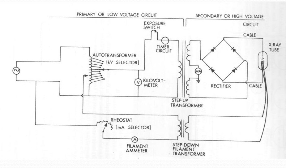
Primary/Low Voltage X-Ray Circuit Components
autotransformer, kV meter, exposure switch, timer circuit
Secondary/High Voltage X-Ray Circuit
mA meter, rectifier, x-ray tube
X-Ray Circuit
Digital Image Viewing
1.low light level desirable
2.too much light causes images to appear dark
3.bright light cause pupils to constrict causing images to appear dark
Image Intensification FOV Decreases
output screen image magnified, mA increases, output screen image has improved resolution
X-Ray Tube Targets Heat Capacity Factors
rotation and diameter of anode and focal spot size
Equalization
computer software operation, removes densities that veil image details, compresses contrast scale
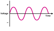
Alternating Current
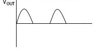
Half Wave Rectification
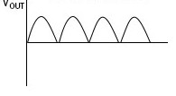
Full Wave Rectification
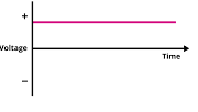
Direct Current
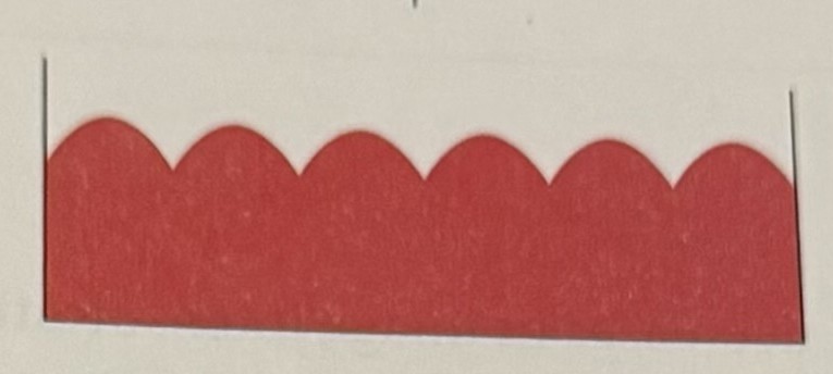
3 Phase 6 Pulse
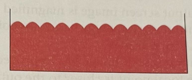
3 Phase 12 Pulse
High Frequency
Flat Panel Fluoroscopy Advantages
greater maneuverability, improved contrast resolution, eliminate need for ADC, considerably smaller size and weight
Blur
unsharp edges of tiny radiographic details
Collimator Evaluation
semiannually
Improve Spatial Resolution of Image-Intensified Images
very thin input phosphor layer, small input phosphor diameter, use magnification mode
X-Ray Tube Characteristics/Qualities
1.target material should have high atomic number and high melting point
2.useful beam emerges from port window
3.cathode assembly receives both low and high voltages
AEC Device
parallel-plate ionization chamber that receives particular charge as x-ray photons travel through it
Total X-Ray Photons Produced at Target Factors
tube current, target material, kV2
Single-Phase Anode Heat Hazard
0.6mm focal spot, 60 kV, 12 mAs
Radiographic Rating Charts
enable radiographer to determine maximum safe milliamperage, exposure time, and kilovoltage for particular exposure and particular x-ray tube
Lowest Heat Exposure
use large focal spot and smaller mAs value
Heat Units Equation
kVp x mAs x MF(3 phase, 6 phase, high)
Cathode Filament Material
thoriated tungsten; liberates electrons through thermionic emission when heated to white hot(incandescence)
Glass Envelope
preserves vacuum necessary for efficient x-ray production
Rotating Anode Material
light weight molybdenum disk with beveled focal track at periphery and stem
Focal Track Material
tungsten rhenium alloy
Focusing Cup Material
nickel; directs liberated filament electrons to the focal spot
Automatic Exposure Rate Control
compensate for changes in patient/part thicknesses, FOV, and OID during flat panel detector fluoroscopic procedures
Large Exposure to Cold Anode or Exceeding Tube Limitation Effects
cracking of anode, rotor-bearing damage, pitting/localized melting of focal track, vaporized tungsten deposits on glass envelope causing decreased tube output
Vaporized Tungsten on Glass Envelope Effects
decreased tube output, acts as additional filtration, possible puncture of glass envelope
kV and HVL Relationship
direct; as one increases the other increases
Window Width Decreases
contrast scale decreases
Solid-State Diode Rectifiers
circuit devices that permits electrons to flow in only one direction; convert AC to DC
Scintillation Types
amorphous silicon, cesium iodide, gadolinium oxysulfide
AEC Backup Timer
protect patient from overexposure and protect x-ray tube from excessive heat
Generator
device that converts mechanical energy to electrical energy
Inherent Filtration
x-ray tube’s glass envelope and its oil coolant; built in filtration that is permanent part of tube head; 0.5-1mm Al equivalent
Slit Camera
measures focal spot size and spatial resolution
Mobile Equipment Requirements
1.exposure switch must be dead man type
2.radiographer must alert individuals in area before making the exposure
3.lead apron must be carried with unit and worn by radiographer during exposure
4.exposure cord must be at least 6ft
Anode Focal Track Pitting Cause
repeated frequent overloading
Collimator Advantages
variety of field sizes available and more efficient beam restriction
Star Pattern
evaluates focal spot accuracy as function of geometric blur
Metallic Element Tungsten Characteristics
readily dissipation of heat, high melting point, high atomic number
Grid Ratio
height of lead strips divided by distance between them
3 Phase 6 Pulse Ripple
13%
Triple Field Image Intensifier Highest Patient Dose
its 12in mode; due to increase electrostatic focusing lenses voltage that causes magnification and dimmer image and mA increased automatically to compensate for it
Image Intensifier with Highest Patient Dose
smaller diameter anodes
3 Phase 12 Pulse Ripple
4%
Voltage Ripple
percentage drop from maximum voltage each pulse of current experiences
High Frequency Generator Ripple
1%
Single Phase Generator Ripple
100%
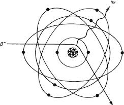
Bremsstrahlung Radiation 1
high speed electron decelerated as it is attracted to tungsten atom nucleus, changes its course, and energy released during braking action
Characteristic Radiation
incident electron ejects a K-shell electron and L-shell electron drops into its place and energy liberated
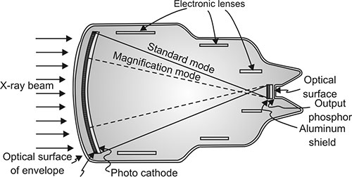
Image Intensifier Parts
input phosphor, photocathode, focusing lenses, accelerating anode, output phosphor
Digital Imaging Components
computer manipulation of image and formation of electronic image on radiation detector
Charge Coupled Device(CCD)
replace image intensifier’s television camera tube in digital fluoroscopy
Radiographic Equipment Check for Linearity and Reproducibility
required annually
Quality Control
regular measurement and evaluation of radiographic equipment components and their performance
Digital Imaging Examples
CT, MRI, CR
Fluoroscopy Automatic Brightness Control
adjust kV and mA
Current
amount of electric charge flowing per second
Voltage
potential difference existing between 2 points
Resistance
property of circuit that opposes current flow
Capacitance
quantity of stored electricity
Radiographic kV Settings Evaluation
required annually
Beam Splitter
device that directs the light emitted from the image intensifier to various viewing and imaging apparatus
Image Intensifier Tube Input Phosphor
convert x-rays to light
Inherent Filtration Contributions
x-ray tube glass envelope and x-ray tube port window
Digital Imaging Subject Contrast
signal differences within the remnant beam
X-Ray Tube
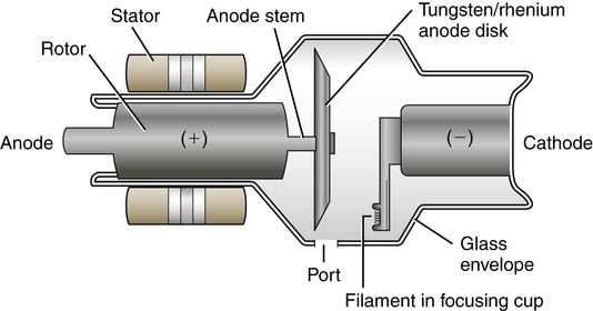
Rotor and Stator Operation
both operate on principle of electromagnetic induction; stator located outside and rotor located inside; both function to rotate the anode
Total Brightness Gain
flux gain x minification gain
Complementary Metal Oxide Semiconductors(CMOS) Advantages
less expensive and much greater speed; produce less image quality
Picture Archiving and Communication System(PACS)
used for reception, display, storage of digital images
Half Value Layer(HVL)
thickness of an absorber that will decrease intensity of beam to ½ its original value
Increase in Heat of the Filament
cause increase in mA due to more electron release during thermionic emission and incandescence
Grid Rule
always use when using high kV and radiographing a large/dense body part
Greatest Detail Sharpness Combinations
smallest target angle and smallest actual focal spot
Image Intensifier Tube
CCD Advantages over Television Cameras in Image Intensification
compact size, improved resolution, higher DQE
X-Ray Tube Rating Chart Maximum Safe kV Requirements
mA, exposure time, and focal spot size
CR Spatial Resolution Increase
PSP crystal size decreases and laser beam size decreases
3 Phase X-Ray tube Voltage
87%-96% of maximum value, nearly constant potential
Proper Projection of Light in Collimator Requirements
focal spot and light bulb distance must be exactly the same distance from the center of the mirror
Image Intensifier Input Phosphor Material
cesium iodide
AEC Essential Function
terminate x-ray exposure once IR is correctly exposed
Grid Interspace Material
aluminum(resists moisture, sturdier, smoother appearance) and plastic fiber(moisture causes warping)
Transformer Law Voltage
Vs/Vp=Ns/Np
Transformer Law Intensity
Ns/Np=Ip/Is
Autotransformer Operation
principle of self induction
Autotransformer Adjustment
kV
Filament Circuit Adjustment
proper current and voltage to x-ray tube filament for proper thermionic emission
Rectifier Circuit Adjustment
changes AC to unidirectional current
Fluoroscopy Brightness Factors
mA, kV, patient thickness
Bremsstrahlung Radiation