SPECT gamma camera QA
1/25
There's no tags or description
Looks like no tags are added yet.
Name | Mastery | Learn | Test | Matching | Spaced | Call with Kai | Chat |
|---|
No analytics yet
Send a link to your students to track their progress
26 Terms
what are the 3 stages of quality assurance
acceptance testing
commissioning
quality control
acceptance testing
ensuring equipment meets purchasing specification → done according to the national electrical manufacturer’s association (NEMA)
sets out specific testing conditions to allow performances to be compared between different systems and manufacturers
test conditions are designed to be replicated by manufacturers in a non lab condition
commissioning
making sure the system is ready for clinical use by measuring
basic QC values
optimising system and setting up protocols
quality control
multiple guidelines available by: IPEM…
periodic testing to find performance declines and ensure consistent performance
quality assurance vs quality control
assurance: setting rules and standard for product quality
control: inspection and testing of the product against the pre-set standards
what do you need to know for QC testing
radionuclide specifications: energy peak(s)
collimator type
energy resolution and energy window
camera area: useful field of view vs central FOV
pixel/matrix size
count rate/density
whether scatter is included
difference between useful and central FOV
useful: edges have degraded imaging capabilities
central: 75% of the UFOV → best part of the camera with minimal degradation
intrinsic measurements
measurements performed without collimators, therefore:
there is no collimator blurring
smaller activity sources can be used
system measurements
measurements performed with collimators
mimics IRL
results are collimator specific
scatter is included: as collimators are used to decrease scatter
how does pixel/matrix size affect image
large matrix → small pixels and vice versa
balance between spatial resolution and sensitivity +noise
smaller pixels → increased resolution but decreased sensitivity → leads to more noise
noise = N
what factors lead to poor image
non-uniform detector response
poor scatter rejection
spatial resolution
detector sensitivity
count-non-linearity
what can lead to detector non-uniformity
different PMT gain
positioning non-linearity
NaI(TI) crystal imperfections
collimator damage → septa damage. angulation errors, uneven hole size
PMT and crystal decoupling
intrinsic uniformity measuring
use a uniform flux source or phantom placed in a lead shield
opening is covered using a copper plate → reduces some of the scattering → acts as a point source
place the source at a distance producing an projection greater than 5 UFOV
Small pixel size is unnecessary as we are measuring the underlying system performance → large pixels are used to reduce noise
9 point smoothing curve is then applied
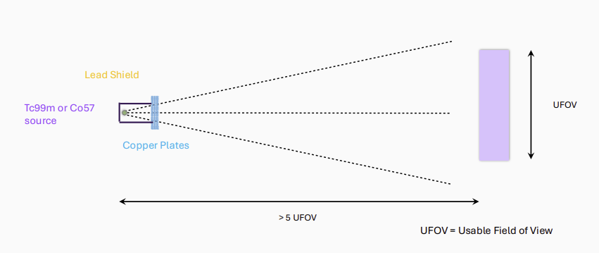
why is a distance of 5 UFOV used in intrinsic uniformity testing?
due to inverse square law I=4πr2Power
at close proximity:
there is a large difference in distance from the source to the edge of the detector compared to the centre
causes a massive drop in intensity at the edges
at 5 UFOV:
difference from source to detector edge and centre is almost negligible as all of the rays are nearly parallel
systemic uniformity test
performed daily
a uniformly distributed activity source is used
As rectangular technetium phantoms are difficult to produce a Co57 source absorbed into resin is used instead
Has similar peak as Tc: 122 compared to 140keV
what are the UFOV and CFOV equations (uniformity types)
integral uniformity → measures global non-uniformity → max and min pixel values anywhere within the FOV
differential uniformity → measures regional non-uniformities → max and min are anywhere within a 5×5 pixel range
both uniformities use the same equation
uniformity=max+minmax−min∗100
good uniformity is anything bellow 5%
what affects intrinsic detector resolution
statistical fluctuation of light photon distribution between photocathode and PMT amplification → causes no. of photons to not be proportional to radiation
spread of light as it travels to the PMT → loss of spatial resolution
multiple scattering within detector
how is intrinsic resolution measured
use the same set up as intrinsic uniformity testing
place 2 mask in front of the source with 1mm slits 30mm apart
we know we should be seeing perfectly straight lines but on the image they may appear distorted
measure the deviation of peak counts from the line of best fit
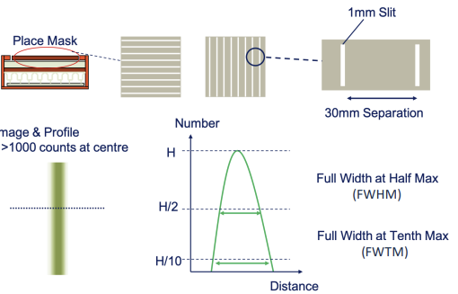
what is differential spatial linearity and integral spatial linearity
Differential Spatial Linearity: Standard deviation of difference between peak locations and fit (typically < 0.2 mm)
Integral Spatial Linearity: Maximum difference between peak location and fit (typically < 0.4 mm)
how is intrinsic system resolution improved
use thinner NaI(Ti) crystal → however decreases stopping power
use more smaller PMT
use higher energy gamma photons → more light is produced
use signal processing and position calculation algorithms
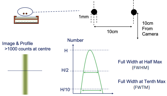
measure system resolution
small sources are placed 10cm from the collimator
system spatial resolution depends on distance from the detector
Measure at 10cm for consistency and because it is realistic
0cm measurements can be effected by position of holes relative to source
or use a bar phantom:
Cobalt-57 flood emitting through a Bar Phantom (strips of lead in resin)
An easy test that can be performed more regularly
Predominantly a qualitative assessment but can be performed quantitatively
Bar phantom can be placed directly on crystal for intrinsic measurements
us Rc equation in notes
what does system planar sensitivity depend on
crystal efficiency
→ increased with thickness and density of crystal
→ decreases with photon energy
energy window width
collimator height and opening width
sensitivity=activity in sourcecounts per sec=MBqCps
how is system planar sensitivity measured
a source with known amount of activity is scanned for a known amount of time
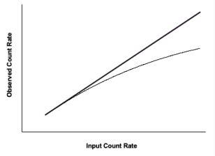
what is dead time
finite amount of time needed to process an event, depends on → light decay in the crystal + electronic processing time
if 2 gamma rays enter the detector in an interval less than the dead time → one or both gamma rays are not detected (lost)
sensitivity at high count rate decreases
sets a maximum limit to detectable count rate
what are the type of dead times
paralysable: When gamma ray enters the detector within the deadtime of the previous event, the deadtime ‘clock’ is restarted (dead time is prolonged_
most gamma cameras are paralysable
Non- paralysable: When gamma ray enters the detector within the deadtime from the previous event, the gamma ray is ignored. Deadtime ‘clock’ is not extended
how is dead time measured
Use a high activity decaying source which you acquire the count rate
Look at the linear response region and then you extrapolate the data to higher count rates
Measure 10%, 20% ect losses
Almost all gamma camera imaging is performed in linear zone