1750 Shoulder Girdle IA
 Call Kai
 Learn
Learn Practice Test
 Spaced Repetition
 Match
Match Flashcards
 Knowt Play
1/48

There's no tags or description
Looks like no tags are added yet.
Name | Mastery | Learn | Test | Matching | Spaced | Call with Kai | Chat |
|---|
No analytics yet
Send a link to your students to track their progress
49 Terms
AP Projection; Shoulder; External Rotation Humerus (CR & SS)
Perpendicular to a point 1 inch (2.5cm) inferior to the coracoid process, which can be palpated inferior to the clavicle and medial to the humeral head
The greater tubercle of the humerus and the site of insertion of the suprspinatus tendon are visualized
AP Projection; Shoulder; External Rotation Humerus (Eval Criteria)
• Evidence of proper collimation
• Superior scapula, clavicle (entire if IR crosswise, lateral half if IR lengthwise), and proximal humerus
• Soft tissue around the shoulder, along with bony trabecular detail
• Humeral head in profile
• Greater tubercle in profile on lateral aspect of the humerus
• Scapulohumeral joint visualized with slight overlap of humeral head on glenoid cavity
• Outline of lesser tubercle between the humeral head and greater tubercle
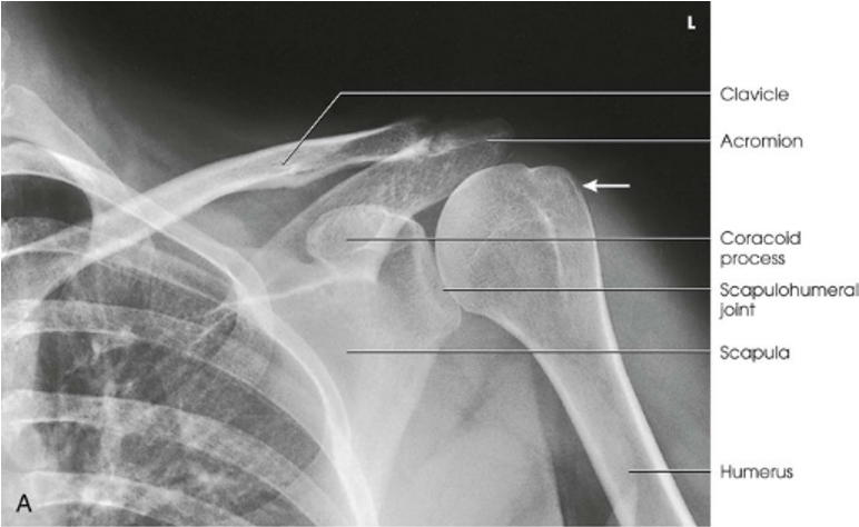
AP Projection; Shoulder; External Rotation Humerus
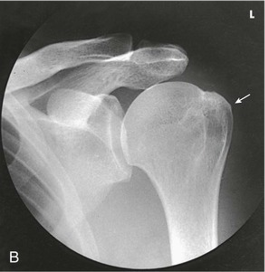
AP Projection; Shoulder; External Rotation Humerus (Round Picture)
AP Projection; Shoulder; Neutral Rotation Humerus (CR & SS)
Perpendicular to a point 1 inch (2.5 cm) inferior to the coracoid process, which can be palpated inferior to the clavicle and medial to the humeral head
The posterior part of the supraspinatus insertion, which sometimes profiles small calcific deposits not otherwise visualized
AP Projection; Shoulder; Neutral Rotation Humerus (Eval Criteria)
• Evidence of proper collimation
• Superior scapula, clavicle (entire if IR crosswise, lateral half if IR lengthwise), and proximal humerus
• Soft tissue around the shoulder, along with bony trabecular detail
• Greater tubercle partially superimposing the humeral head
• Humeral head in partial profile
• Slight overlap of the humeral head on the glenoid cavity
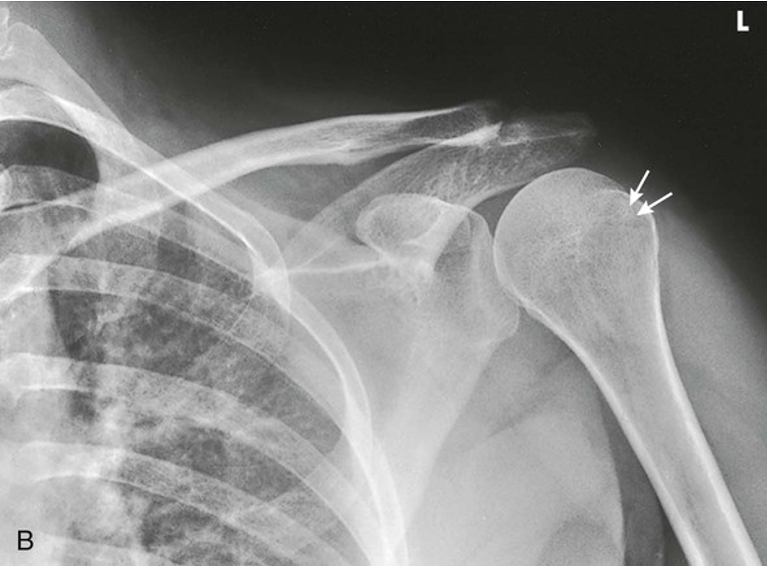
AP Projection; Shoulder; Neutral Rotation Humerus
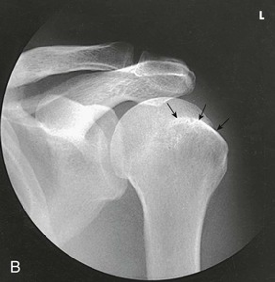
AP Projection; Shoulder; Neutral Rotation Humerus (Round Picture)
AP Projection; Shoulder; Internal Rotation Humerus (CR & SS)
Perpendicular to a point 1 inch (2.5 cm) inferior to the coracoid process, which can be palpated inferior to the clavicle and medial to the humeral head
The proximal humerus is seen in a true lateral position. When the arm can be abducted enough to clear the lesser tubercle of the head of the scapula, a profile image of the site of insertion of the subscapular tendon is seen
AP Projection; Shoulder; Internal Rotation Humerus (Eval Criteria)
• Evidence of proper collimation
• Superior scapula, clavicle (entire if IR crosswise, lateral half if IR lengthwise), and proximal humerus
• Soft tissue around the shoulder, along with bony trabecular detail
• Lesser tubercle in profile and pointing medially
• Outline of the greater tubercle superimposing the humeral head
• Greater amount of humeral overlap of the glenoid cavity than in external and neutral positions
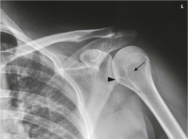
AP Projection; Shoulder; Internal Rotation Humerus
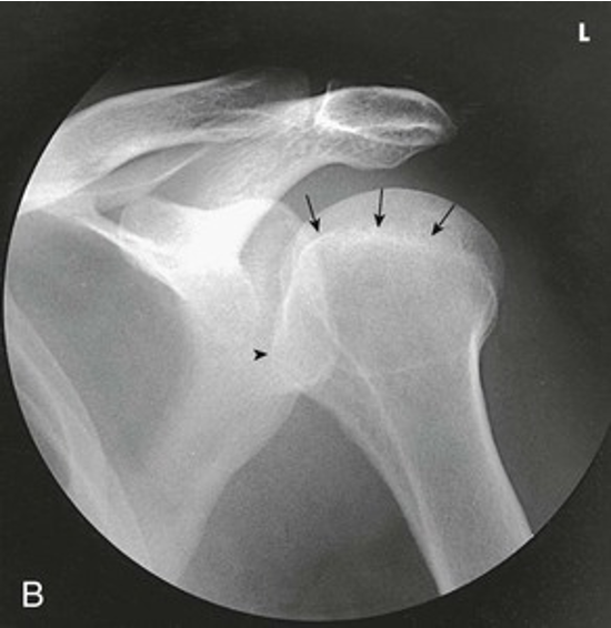
AP Projection; Shoulder; Internal Rotation Humerus (Round Picture)
How do we determine rotation of the patient, not humeral head, the entire patient in AP Shoulder projections.
• Foreshortening/elongation of the clavicle
• Foreshortening/elongation of the ribs
• Open glenoid cavity
Inferosuperior Axial Projection; Shoulder Joint; Lawrence Method (CR & SS)
Horizontally through the axilla to the region of the AC articulation. The degree of medial angulation of the central ray depends on the degree of abduction of the arm. The degree of medial angulation is often between 15 degrees and 30 degrees. The greater the abduction, the greater the angle
An inferosuperior axial image shows the proximal humerus, the scapulohumeral joint, the lateral portion of the coracoid process, and the AC articulation. The insertion site of the subscapular tendon on the lesser tubercle of the humerus and the point of insertion of the teres minor tendon on the greater tubercle of the humerus are also shown
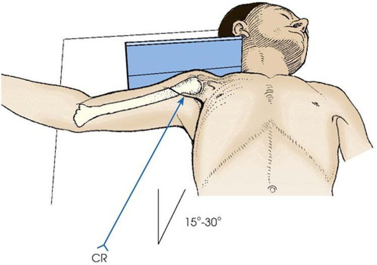
Epicondyles are parallel to floor. Hand in external rotation
POSITIONING: Inferosuperior Axial Projection; Shoulder Joint; Lawrence Method
Inferosuperior Axial Projection; Shoulder Joint; Lawrence Method (Eval Criteria)
• Evidence of proper collimation
• Scapulohumeral joint with slight overlap
• Coracoid process, pointing anteriorly
• Lesser tubercle in profile and directed anteriorly
• AC joint, acromion, and acromial end of clavicle projected through the humeral head
• Soft tissue in the axilla with bony trabecular detail
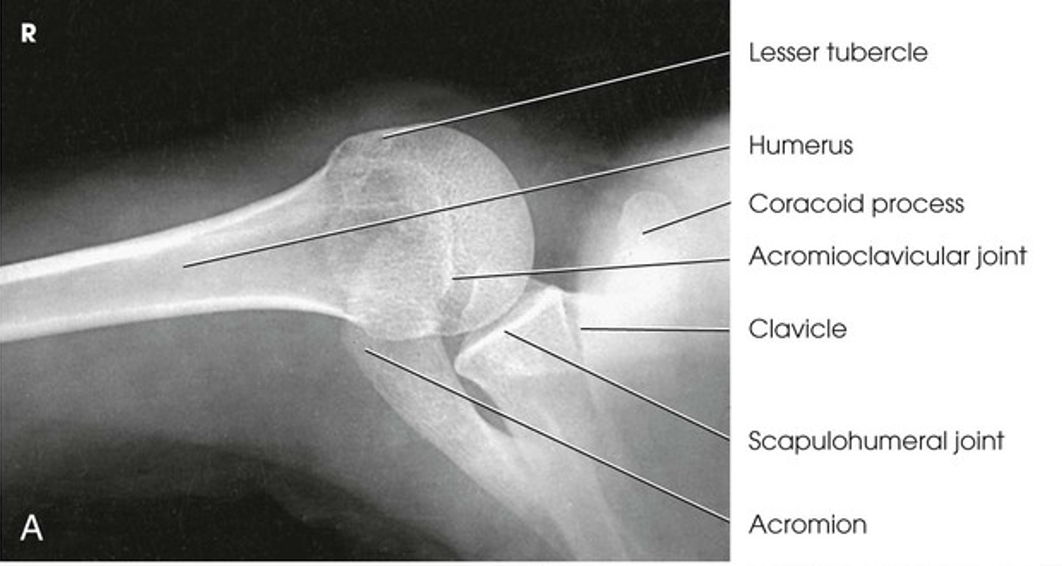
Inferosuperior Axial Projection; Shoulder Joint; Lawrence Method
PA Oblique Projection; Shoulder Joint; Scapular Y; RAO or LAO Position (CR & SS)
Perpendicular to the scapulohumeral joint
The scapular Y is shown on an oblique image of the shoulder. In the normal shoulder, the humeral head is directly superimposed over the junction of the Y.
PA Oblique Projection; Shoulder Joint; Scapular Y; RAO or LAO Position (Eval Criteria)
• Evidence of proper collimation
• Humeral head and glenoid cavity superimposed
• Humeral shaft and scapular body superimposed
• No superimposition of the scapular body over the bony thorax
• Acromion projected laterally and free of superimposition
• Coracoid possibly superimposed or projected below the clavicle
• Scapula in lateral profile with lateral and vertebral borders superimposed
• Soft tissues and bony trabecular detail
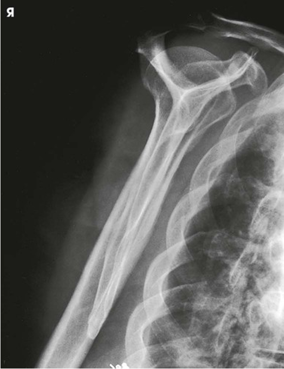
PA Oblique Projection; Shoulder Joint; Scapular Y; RAO or LAO Position
Transthoracic Lateral Projection; Shoulder; Lawrence Method; Right or left lateral position (CR & SS)
Perpendicular to the IR, entering the mid-coronal plane at the level of the surgical neck
If the patient cannot elevate the unaffected shoulder, angle the central ray 10-15 degrees cephalad to obtain a comparable radiograph
A lateral image of the shoulder and proximal humerus is projected through the thorax
Transthoracic Lateral Projection; Shoulder; Lawrence Method; Right or left lateral position (Eval Criteria)
• Evidence of proper collimation
• Proximal humerus
• Scapula, clavicle, and humerus seen through the lung field
• Scapula superimposed over the thoracic spine
• Unaffected clavicle and humerus projected above the shoulder closest to the IR
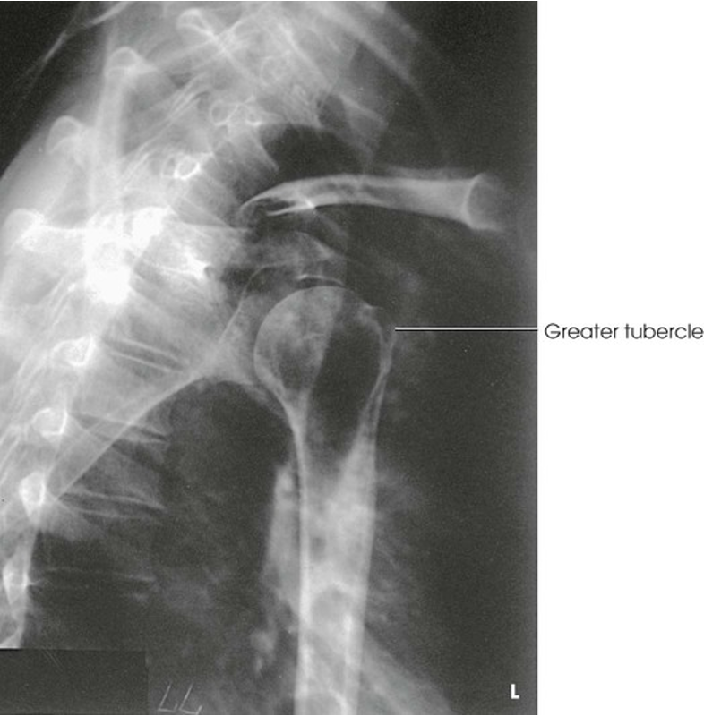
Transthoracic Lateral Projection; Shoulder; Lawrence Method; Right or left lateral position
AP Oblique Projection; Shoulder Joint; Glenoid Cavity; Grashey Method; RPO or LPO Position (CR & SS)
Perpendicular to the IR; the central ray should be at a point 2 inches (5 cm) medial and 2 inches (5 cm) inferior to the superolateral border of the shoulder
The joint space between the humeral head and the glenoid cavity (scapulohumeral or glenohumeral joint) is shown
AP Oblique Projection; Shoulder Joint; Glenoid Cavity; Grashey Method; RPO or LPO Position (Eval Criteria)
• Evidence of proper collimation
• Open joint space between the humeral head and glenoid cavity
• Glenoid cavity in profile
• Soft tissue at the scapulohumeral joint along with trabecular detail on the glenoid and humeral head
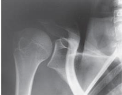
AP Oblique Projection; Shoulder Joint; Glenoid Cavity; Grashey Method; RPO or LPO Position
AP Projection; Scapula (CR & SS)
Perpendicular to the midscapular area at a point approximately 2 inches (5 cm) inferior to the coracoid process
An AP Projection of the scapula is shown
AP Projection; Scapula (Eval Criteria)
• Evidence of proper collimation
• Lateral portion of the scapula free of superimposition from the ribs
• Scapula horizontal and not slanted
• Scapular detail through the superimposed lung and ribs (shallow breathing should help obliterate lung detail)
• Acromion and inferior angle
• Soft tissues and bony trabecular detail
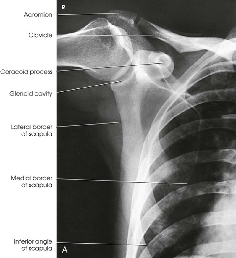
AP Projection; Scapula
Lateral Projection; Scapula; Scapula Y; RAO or LAO body position (CR & SS)
Perpendicular to the mid-medial border of the protruding scapula
A lateral image of the scapula is shown by this projection. The placement of the arm determines the portion of the superior scapula that is superimposed over the humerus
Lateral Projection; Scapula; Scapula Y; RAO or LAO body position (Eval Criteria)
• Evidence of proper collimation
• Lateral and medial borders superimposed
• No superimposition of the scapular body on the ribs
• No superimposition of the humerus on the area of interest
• Inclusion of the acromion and inferior angle
• Lateral thickness of scapula with proper brightness
• Soft tissues and bony trabecular detail
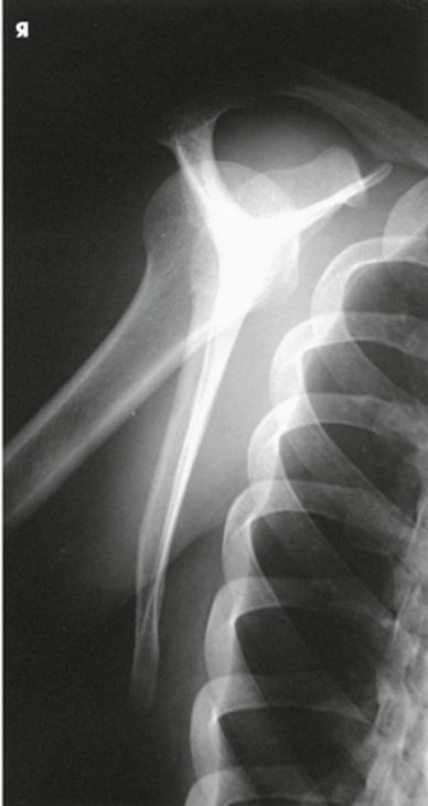
Lateral Projection; Scapula; Scapula Y; RAO or LAO body position (Arm on posterior chest, shows acromion/coracoid)
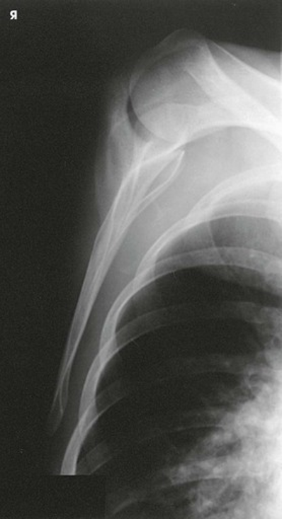
Lateral Projection; Scapula; Scapula Y; RAO or LAO body position (Arm across upper anterior thorax, shows body)
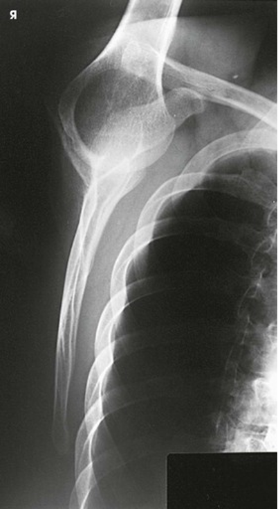
Lateral Projection; Scapula; Scapula Y; RAO or LAO body position (Arm extended above head, shows body)
AP Projection; Clavicle (CR & SS)
Perpendicular to the mid-shaft of the clavicle
This projection shows a frontal image of the clavicle
*Do PA when improved spatial resolution is desired. PA Projection places clavicle closer to film, thus reducing OID
AP Projection; Clavicle (Eval Criteria)
• Evidence of proper collimation
• Entire clavicle centered on the image
• Lateral half of the clavicle above the scapula, with the medial half superimposing the thorax
• Soft tissues and bony trabecular detail
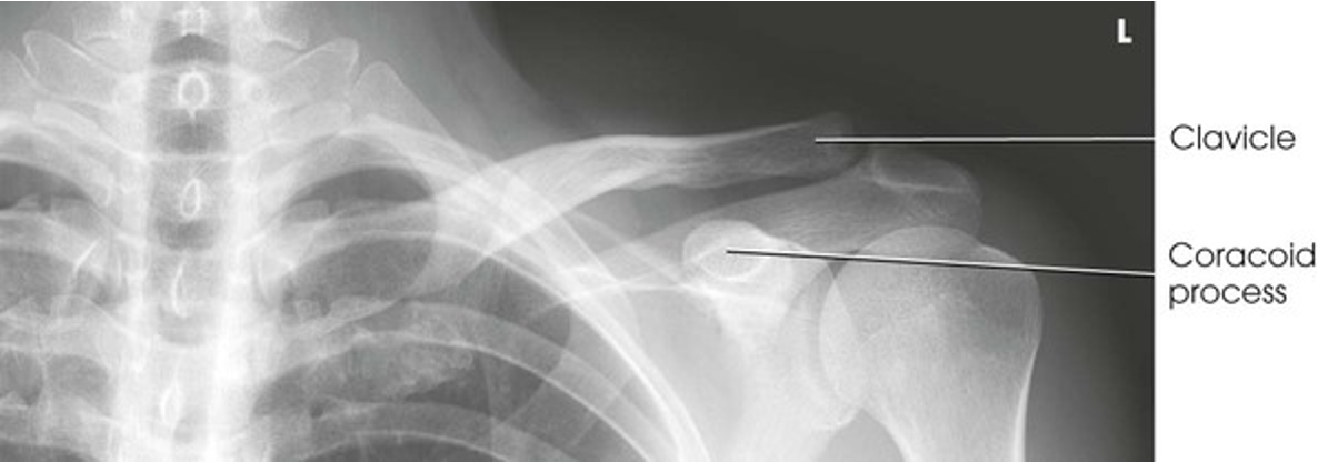
AP Projection; Clavicle
AP Axial Projection; Clavicle (CR & SS)
This is directed to enter the midshaft of the clavicle
Cephalic central ray angulation can vary from the long axis of the torso; thinner patients require increased angulation to project the clavicle off the scapula and ribs
For the standing lordotic position, 0 to 15 degrees is recommended
For the supine position, 15 to 30 degrees is recommended
An axial image of the clavicle is projected above the ribs
AP Axial Projection; Clavicle (Eval Criteria)
• Evidence of proper collimation
• Most of the clavicle projected above the ribs and scapula with the medial end overlapping the first or second rib
• Clavicle in a horizontal placement
• Entire clavicle along with AC and SC joints
• Soft tissues and bony trabecular detail
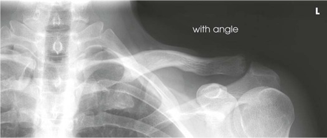
AP Axial Projection; Clavicle
AP Projection; Acromioclavicular Articulations; Pearson Method; Bilateral (CR & SS)
Perpendicular to the midline of the body at the level of the AC joints for a single projection; directed at each respective AC joint when two separate exposures are necessary for each shoulder in broad-shouldered patients
Bilateral images of the AC joints are shown. This projection is used to show dislocation, separation, and function of the joints
AP Projection; Acromioclavicular Articulations; Pearson Method; Bilateral (Eval Criteria)
• Evidence of proper collimation
• AC joints visualized with some soft tissue and without excessive density
• Both AC joints, with and without weights, entirely included on one or two single radiographs
• No rotation or leaning by the patient
• Right or left and weight or non-weight markers
• AC joint separation, if present, clearly seen on the images with weights
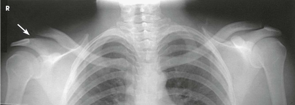
AP Projection; Acromioclavicular Articulations; Pearson Method; Bilateral (Bilateral AP AC joints showing normal left joint and separation of right joint (arrow)
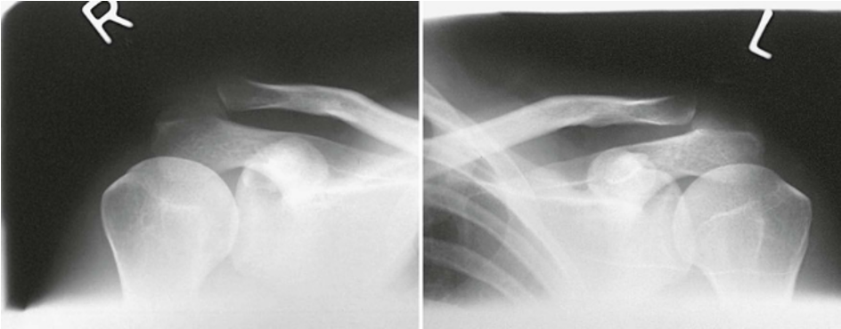
AP Projection; Acromioclavicular Articulations; Pearson Method; Bilateral (Normal AC joints requiring two separate radiographs)
Tangential Projection; Supraspinatus “Outlet”; Shoulder Joint; Neer Method; RAO or LAO position (CR & SS)
Angled 10-15 degrees caudad, entering the superior aspect of the humeral head
The tangential outlet image shows the posterior surface of the acromion and the AC joint identified as the superior border of the coracoacromion outlet
Shoulder impingement: involves tendonitis of the rotator cuff muscles as they pass through the subacromial space (tendonitis of supraspinatus muscle)
Tangential Projection; Supraspinatus “Outlet”; Shoulder Joint; Neer Method; RAO or LAO position (Patient Position)
Patient rotated 45-60 degrees
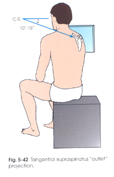
Tangential Projection; Supraspinatus “Outlet”; Shoulder Joint; Neer Method; RAO or LAO position (Eval Criteria)
The side marker placed clear of anatomy of interest
Humeral head projected below the AC joint
Humeral head and AC joint with bony detail
Humerus and scapular body, generally parallel
Bony trabecular detail and surrounding soft tissues
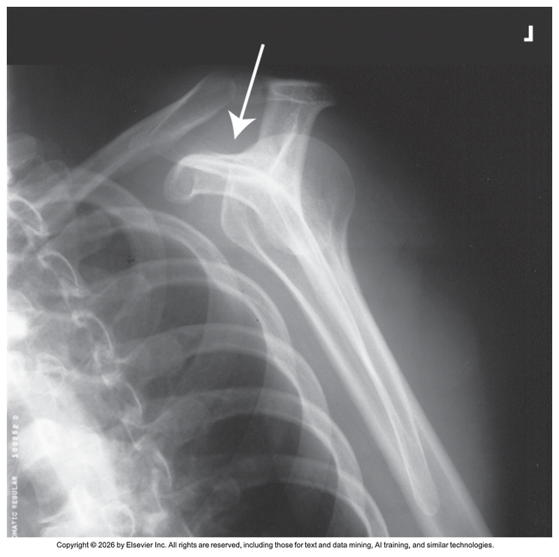
Tangential Projection; Supraspinatus “Outlet”; Shoulder Joint; Neer Method; RAO or LAO position
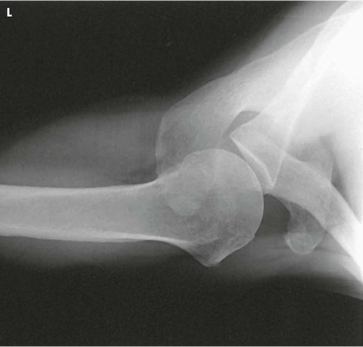
Inferosuperior Axial Projection; Shoulder Joint; West Point Method