Boolean Logic
1/29
Earn XP
Description and Tags
Logic Gates + Boolean Algebra + Algebraic Expressions + Adders + D-Type Flip Flops + Simplifying Boolean Expressions + De Morgan's Law
Name | Mastery | Learn | Test | Matching | Spaced | Call with Kai |
|---|
No analytics yet
Send a link to your students to track their progress
30 Terms
Define Boolean Algebra
Logical calculus of truth tables
developed by George Boole (late 1830s)
resembles algebra of real numbers but with numeric operations of: multiplication, addition and negation
variables cam either be TRUE or FALSE (1s & 0s / 5v & 0v)
what is a logic gate
circuits which take boolean inputs and convert them to boolean output
and
or
not
nand
nor
xor
xnor
drawing truth tables: TRICK
n inputs = 2n lines in truth table
e.g. 3 inputs = 23 = 8 lines in truth table
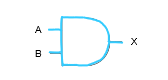
Draw the symbol, algebraic representation and truth table for the AND gate:
A.B
0.0 = 0
0.1 = 0
1.0 = 0
1.1 = 1
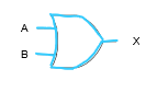
Draw the symbol, algebraic representation and truth table for the OR gate:
A+B
0+0 = 0
0+1 = 1
1+0 = 1
1 +1 = 1
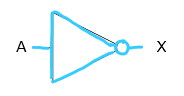
Draw the symbol, algebraic representation and truth table for the NOT gate:
A with a dash on top
NOT 0 = 1
NOT 1 = 0
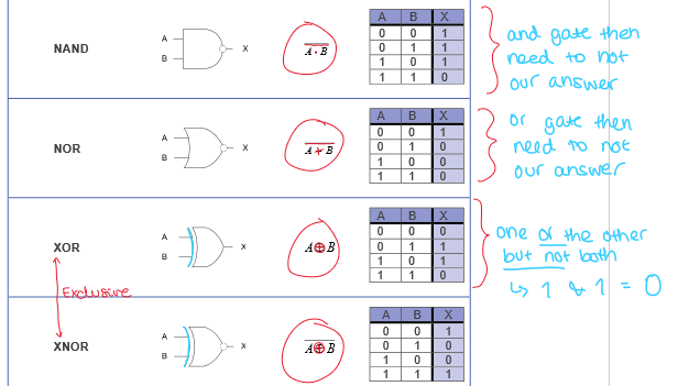
draw the symbol, algebraic representation and truth table for NAND, NOR, XOR, XNOR gates:
Why do we want to reduce the number of gates in our algebraic representation?
Processor needs to be as small & energy efficient as possible
What is the Order of Precedence for Boolean operators?
Brackets first
NOT second
AND third
OR last
What are the ways we can output binary arithmetic?
logic gates
Half-adder
Full Adder
D-type flip flops
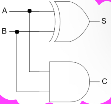
What is a half-adder
Takes 2 inputs & returns two outputs corresponding to the sum & carry when two inputs are added together
What does a half-adder look like?
What does the truth table for a half adder look like?
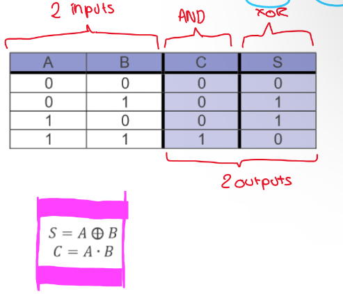
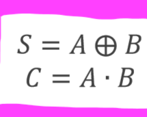
what does the boolean algabreic equation look like for a half adder
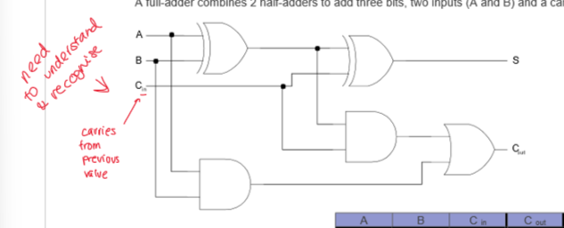
What is a full adder
combines two half adders to add three bits (2 inputs (A & B) and carry a bit (C))
What does a full adder look like?
(dont need to redraw but have to understand and recognise)
what does the truth table for a full adder look like?
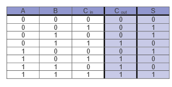
what does the boolean algabreic equation look like for a full adder
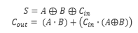
what can full adders be used for
multiple full adders can be connected together to add whole binary numbers together
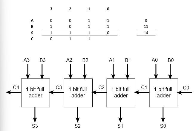
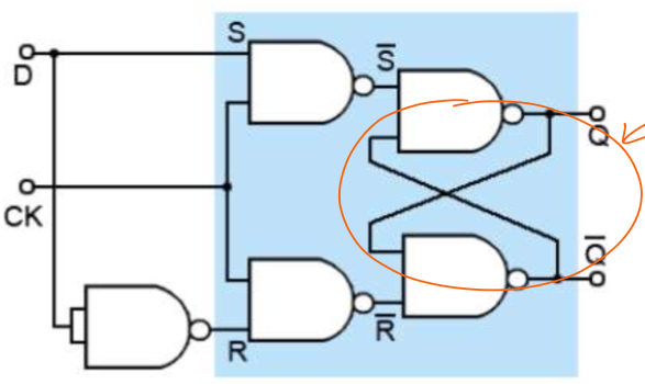
what’s a d- type flip flop?
an elemental sequential logic circuit that stores one bit and flips between two states (0, 1).
how does the d-type flip flop work?
has 2 inputs: D & CK (clock signal)
has 2 outputs: Q & inverse Q
clock signal changes at regular intervals to synchronise the change of state of flip-flop circuit
its effectively 1- bit memory
recursive
keeps data consistent
draw a d-type flip-flop using logic gates:
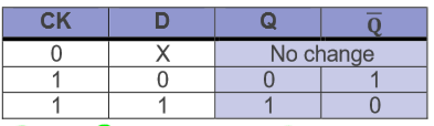
draw the truth table for a d-type flip-flop
X = ‘don’t care‘ state = changes at the D input make no difference to the output as long as the clock input is 0. when CK = 1, there is a change.
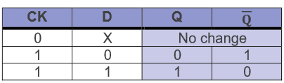
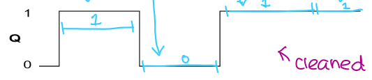
describe what happens in a d-type flip-flop when the CK is high (1):
whichever logic state is at D will appear at output Q. that way you can work out the other output (inverse of Q = opposite of Q)
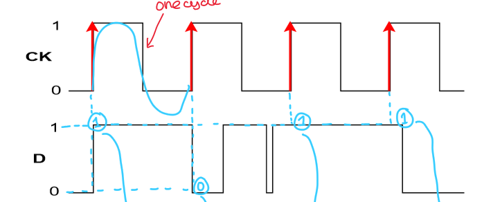
draw this data as cleaned data:
cleaned data has now been outputted for Q to keep data consistent
what is the process of reducing the number of logic gates called and why do we use it?
minimisation
improve efficiency - computer can carry out the same task in fewer steps, therefore, reducing time to solve boolean algebra
SIMPLIFYING BOOLEAN EXPRESSIONS:
normal maths rules:
A + B = B + A
A . B = B . A
A + (B + C) = (A + B) + C
A. (B + C) = A . B + A . C - expanding
(A + B) . (A + C) = A + (B . C) - factorising
SIMPLIFYING BOOLEAN EXPRESSIONS:
using truth tables
A . A = A
A . 0 = 0
A . 1 = A
A . NOTA = 0
A + A = A
A + 0 = A
A + 1 = 1
A + NOTA = 1
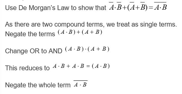
De Morgan’s Law
negate individual variables
change the operator
negate whole expression
advantages of using de morgan’s law
minimises cost of production
increases processing speed
minimises heat generated
reduces power consumption