ch-4 oscillators
1/144
Earn XP
Description and Tags
Name | Mastery | Learn | Test | Matching | Spaced | Call with Kai |
|---|
No analytics yet
Send a link to your students to track their progress
145 Terms
In electronics periodic signals of various shapes such as …. are often needed to perform different types of operation
sinusoids, triangular, rectangular and pulses
the term oscillator is generally referred to as generator of
sinusoid signals,
a rectangular wave generator is more commonly known as
a mulitivibrator
An oscillator generates
an ac output signal without requiring any form of input signal.
The signal - generating devices have certain fundamental elements in common, these are :
conversion of direct, or constant voltage to a particular periodically varying voltage,
the manipulation of that voltage to a desired wave shape , and
the precise control of the magnitude and frequency of that voltage.
Generally an oscillator circuit consists of:
• An amplifier circuit
• A positive feedback circuit
• Frequency determining components
Three requirements for an oscillation to sustain are:
• Positive feedback 360deg phaseshift
• An initial input trigger to start oscillations
• Barkhausen criterion: loop gain(𝛽𝐴) = 1
What is the loop gain in a feedback circuit?
A: The loop gain is the product of the gain of the base amplifier (A) and the feedback gain (β), denoted as βA
Q: What condition must be met for the feedback voltage (Vf) to be equal to the input voltage (Vi)?
For the feedback voltage to be equal to the input voltage, the product βA\beta AβA must have the correct magnitude and phase
hat does the condition βA=1 signify in the context of oscillators?
The condition βA=1\beta A = 1βA=1 is known as the Barkhausen criterion for oscillation, indicating that the feedback voltage is the proper input voltage to drive the amplifier and feedback circuits, sustaining loop operation and ensuring the output waveform exists.
What is the significance of the Barkhausen criterion in oscillator circuits
A: The Barkhausen criterion (βA=1\beta A = 1βA=1) ensures that the feedback voltage is adequate to drive the amplifier and feedback circuits, thereby sustaining oscillations.
feedback analysis, what roles do the base amplifier and feedback network play?
A: The base amplifier provides the initial gain, while the feedback network modifies the signal and provides the necessary feedback gain (β\betaβ). Together, they determine the loop gain (βA)
What happens if the loop gain βA\beta AβA is not equal to 1?
If the loop gain βA\beta AβA is not equal to 1, the oscillations will not be sustained
.
If βA<1\ the oscillations will____, and
if βA>1, the oscillations will
decay
grow until non-linear effects limit the amplitude.
Sinusoidal oscillators use ______ generator circuits to produce signals ranging from a low audio frequency to very high radio and microwave frequencies,
sine wave
are constructed using
resistor, capacitor and/or inductor
Many low frequency type sine wave generators use _____&_______to form their frequency determining network and are referred to as____________(shown in fig
resistors and capacitors
RC Oscillators
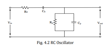
The frequency of RC oscillator circuit shown in figure s given by
𝜔𝑟 = 1 /𝑅p𝐶p
ones that generate high frequency waves (up to 500 MHz) uses
inductors and capacitors

they are called
LC tank circuits
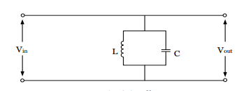
The frequency of LC tank in fig is given by:
𝜔𝑟 = 1 /√𝐿C
A third type sinusoidal oscillator uses RLC resonant circuit and is known as
the crystal-controlled oscillator,It produces very high and fixed frequency waves with excellent frequency stability and a greater quality
The frequency of oscillation of RLC circuit can be found from the crystal impedance, where the impedance ZS (using S domain) is given by:
𝑍𝑆 = 𝑋𝐿 +𝑋𝐶𝑆 = 𝑆𝐿 + 1/𝑆Cs
𝑍𝑃=
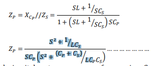
the crystal circuit has two resonance frequencies:
Series (𝜔𝑆 ) and Parallel (𝜔𝑃)
𝜔𝑆 =
1 /√𝐿𝐶s
𝜔𝑃 =
1 √𝐿 ( 𝐶p𝐶s/ 𝐶p + 𝐶s )
for LC tank circuit, 𝐸 /𝐿 =
A
for LC basic tank, I in frequency domain
𝑖 = 𝐴 ∗ 𝑆/(𝑆²+ 𝜔²)
i in time domain by inverse laplace
𝑖(𝑡) = 𝐴 ∗ 𝑐𝑜𝑠(𝜔𝑡) …
This proves that the output wave shape of a tank circuit is a sinusoidal wave.
it’s frequency hence given as
𝑓 = 1/2𝜋√𝐿𝐶
If there were no internal resistance in a tank circuit, oscillations would continue indefinitely
true. Each resonant circuit, however, contains some resistance, which dissipates power. This Power loss causes the amplitude to decrease as
The reduction of oscillation amplitude in an oscillator circuit is defined of
damping
______— and_______ resistances cause damping
Tank&load
. The larger the tank resistance the greater is the amount of damping.
true
The effect of tank damping in oscillators is overcome by applying
regenerative feedback.
give one RC Oscillator
Wien-Bridge Oscillator
This oscillator circuit is constructed using :
an op-amp, which is connected in a noninverting configuration,
two RC bridge circuits used to determine the frequency of oscillation.
give it’s schematic
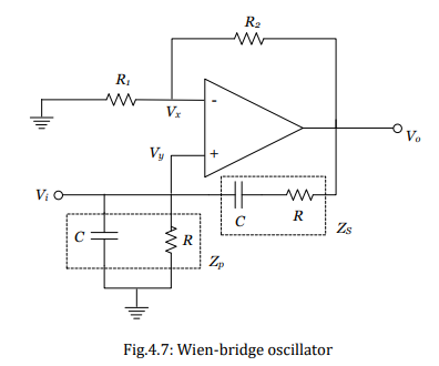
The loop gain is the product of
he amplifier gain and the feedback transfer function.
The amplifier gain is given by
𝐴 = (1 + 𝑅2/𝑅1 ),the same expression as given by the non inverting op-amp amplifi
the feedback transfer function is given by
𝛽 = 𝑍𝑝 /(𝑍𝑝 + 𝑍s)
we could get the frequency of oscillation as:
𝜔 = 1 /𝑅c
𝑅2 /𝑅1 =
2
Hence, to have a sufficient loop gain for the circuit to oscillate at a frequency f given above, we must have
𝑅2⁄𝑅1 > 2.
The most commonly used types of LC oscillators are
the Colpitts and Hartley Oscillators,
which can be constructed using
BJT, FET or ICs.
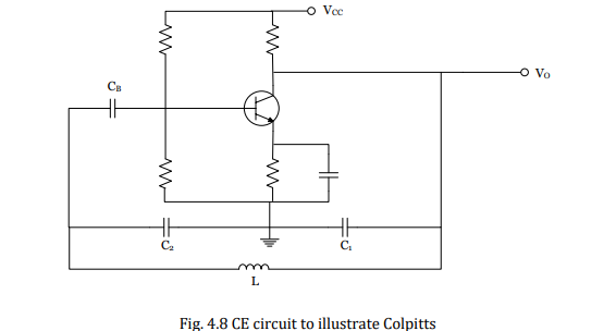
The identification feature of a Colpitts Oscillator is
split capacitor.
. The two capacitors (C1 and C2 in figure 4.8) in the frequency-determining device provide the oscillator with capacitive feedback. Thus, Colpitts Oscillators use split capacitors for capacitive feedback.
The small signal ac equivalent circuit is shown below, taking the assumption that at the frequency of oscillation 𝑟𝜋 ≫ 1⁄𝜔𝐶2 and the resistance R includes 𝑟𝑜 of the transisto
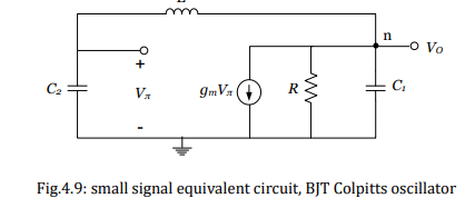
the output voltage appears across __ and the feedback voltage appears across __.
C1
C2
For oscillations to start, both the real and imaginary parts must be zero. Equating the imaginary part to zero gives us the frequency of oscillation as follows:
𝜔 = 1 √𝐿 ( 𝐶1𝐶2/(𝐶1 + 𝐶2 ))
And equating the real part to zero and substituting the above equation for 𝜔 we get,𝑔𝑚𝑅 =
𝐶2 /𝐶1
the gain of the base amplifier is equal to the ratio of the capacitive reactance
true
And for oscillations to start the loop gain must be made greater than unity. i.e
𝑔𝑚𝑅 > 𝐶2/C1
The transistors non linear characteristics reduce the effective value of 𝑔𝑚 , and thus reduce the loop gain to unity, which helps the circuit to sustain the oscillation.
true
Using Barkhausen criteria 𝛽 =
𝛽 = 1 /𝑔𝑚𝑅 = 𝐶1/c2
This is the feedback gain of the oscillating circuit.
Hartley Oscillator, The identifying feature of this oscillator is
a tapped coil for inductive feedback.
The ac equivalent circuit for the Hartley oscillator is shown in figure
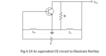
For this circuit the output voltage appears across __ and the feedback voltage appears across __
L1
L2
frequency of the oscillating ckt =
𝜔 = 1 /√(𝐿1 + 𝐿2 )C
dthe analysis for the feedback gain and the minimum voltage gain is as given below
𝛽 = 𝑉𝑓/ 𝑉𝑂 = 𝑋𝐿2 /𝑋𝐿1 = 𝐿2 /𝐿1
𝐴𝑣 = 𝑉𝑂 /𝑉𝑓 = 𝑋𝐿1 /𝑋𝐿2 = 𝐿1/𝐿2 …jus the reverse of ea
the value when mutual insudtance is involved will be
L1+L2+2M
how do we indentify the signs of 2M?
is +ve if L1&L2 rv aiding
-ve if the inductors are series opposing
Wave Form Generator Circuits
are non sinusoidal oscillator circuits which generates complex wave shapes
Multivibrators :These are most often used to generate
square or triangular waves
s. A multivibrator is basically
two-amplifier circuits arranged with regenerative feedback
.Usually one of the amplifiers is conducting while the other is cutoff.
true
In general, there are three types of multivibrators namely
Astable, Monostable and Bistable
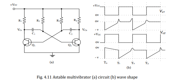
Astable (free running) multivibrator
Has no stable state. With no external signal applied, the two active devices (transistors) alternatively switch from cutoff to saturation,
they do so at a frequency determined by
the RC time constants of the coupling circuits.
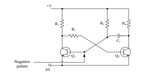
Its circuit and wave form is
What causes one of the transistors (say Q1) in the astable multivibrator circuit to turn on faster than the other when the circuit is first switched on?
Due to slight differences in the characteristics of the two transistors, the current through one transistor (Q1) increases faster than through the other (Q2).
Q: What is the result of the increase in current through Q1 in the astable multivibrator circuit?
A: The increase in current through Q1 causes the voltage across resistor R1 to increase, which leads to a fall in the collector voltage of Q1.
Q: How does the fall in collector voltage of Q1 affect Q2 in the astable multivibrator circuit?
A: The fall in collector voltage of Q1 is coupled to the base of Q2, causing the collector current of Q2 to fall and its collector voltage to rise.
Q: What is the cumulative effect in the astable multivibrator circuit when Q1 becomes fully on and Q2 completely off?
A: The cumulative effect causes Q1 to become rapidly fully on and Q2 to become completely off. This is due to the increasing forward bias of Q1, which aids in the rise of its collector current.
Q: What happens to capacitor C1 when Q1 is on and Q2 is off?
A: Capacitor C1 begins to charge from the supply rail via resistor R2, causing the voltage on the right-hand side of C1 to rise and eventually turning Q2 on and Q1 off.
Q: Describe the charging and discharging cycle of capacitor C2 in the astable multivibrator circuit.
A: When Q2 is on and Q1 is off, capacitor C2 charges from the supply via resistor R3. As the voltage on the left-hand side of C2 begins to rise, it increases the base voltage of Q1, turning Q1 on and Q2 off, repeating the cycle.
Q: What happens in the circuit from T0 to T1?
A: From T0 to T1, Q1 is saturated (fully on), Q2 is in cutoff, and its collector voltage is at Vcc. The base wave shape for Q2 indicates a negative signal moving towards zero due to C1 discharging, while the base voltage of Q1 is positive to keep it in saturation.
Q: What happens in the circuit from T1 to T2
A: From T1 to T2, Q1 is in cutoff, and Q2 is saturated. This condition remains until capacitor C2 discharges enough to allow Q1 to conduct at T2.
Q: What is the overall behavior of the astable multivibrator circuit?
A: The circuit continuously switches between two states, with Q1 and Q2 alternately turning on and off, causing capacitors C1 and C2 to charge and discharge in a repeated cycle.
The monostable has only__ permanent stable state
one
When triggered by an external pulse, it changes over to an unstable state for a time determined by
a CR time constant.t. It then reverts to its stable state and waits for another trigger pulse.
Monostable multivibrator circuit
What happens to Q1 when the circuit is first switched on in a monostable multivibrator?
A: When the circuit is first switched on, Q1 is forward biased by resistor R3, which turns Q1 hard on, resulting in a high collector current and a low collector voltage.
How does the low collector voltage of Q1 affect Q2?
A: The low collector voltage of Q1 is cross connected to the base of Q2, turning Q2 off. This establishes the stable state of the circuit.
Q: What triggers the monostable multivibrator to move from the stable state to the unstable state?
A: A negative pulse to the base of Q1 turns Q1 off, causing its collector voltage to go high and turning Q2 on, thereby moving the circuit into the unstable state.
Q: What role does capacitor C1 play in the unstable state of the monostable multivibrator?
A: In the unstable state, capacitor C1 charges from the supply rail via resistor R3. This charging process eventually raises the voltage on the left-hand side of C1.
Q: What happens when the voltage on the left-hand side of C1 becomes high enough?
A: When the voltage on the left-hand side of C1 becomes high enough, it turns Q1 back on. This, in turn, switches Q2 off, bringing the circuit back to its stable state
Q: What are two possible applications of a monostable multivibrator?
A: The monostable multivibrator can be used as a short duration timer or a pulse width stretcher.
Bistable Multivibrator It has __ stable states
2
. It remains in one of the stable states until a trigger is applied, then it goes to the other stable condition to remain these until another trigger is applied to change it back to the original stable state.
Bistable multivibrator schematics
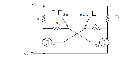
This circuit is similar to an astable multivibrator, except that
there is no charge or discharge time, due to the absence of capacitors
. Hence, when the circuit is switched on, if Q1 is
on, its collector is at 0 V
As a result, Q2 gets
switched of
. This results in
more than half +V volts being applied to R4 causing current into the base of Q1, thus keeping it on.
. Thus, the circuit remains stable in
a single state continuously. Similarly, Q2 remains on continuously, if it happens to get switched on first.
Switching of state can be done via
Set and Reset terminals connected to the bases.
For example, if Q2 is on and Set is grounded momentarily, this switches Q2 off, and makes Q1 on. Thus, Set is used to "set" Q1 on, and Reset is used to "reset" it to off state.
Comparator
It is essentially an op-amp operated in an open loop configuration, which actually compares two voltages to determine the largest.
t. It is usually biased at voltages
+Vs and –Vs, although other biases are possible