Electronic Systems and Design
 Call Kai
 Learn
Learn Practice Test
 Spaced Repetition
 Match
Match Flashcards
 Knowt Play
1/138

There's no tags or description
Looks like no tags are added yet.
Name | Mastery | Learn | Test | Matching | Spaced | Call with Kai | Chat |
|---|
No analytics yet
Send a link to your students to track their progress
139 Terms

Branch of electronics in charge with the manufacture of heavy-duty electronics for industrial uses

“Thyratron” “Transitor”
Acts as a bistable switch, takes high voltages

Silicon Controlled Rectifier / semiconductor-controlled rectifier
4-layer solid-state current-controlling device used in electronic devices that require control of high voltage and power
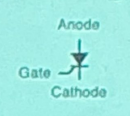
schematic diagram of SCRs
A graphical representation showing the electrical connections and functions of silicon controlled rectifiers in a circuit, including their input and output terminals.
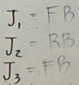
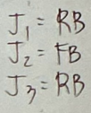
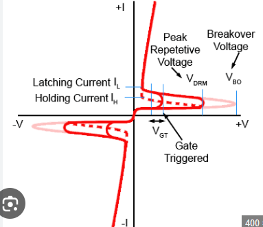
Forward Blocking region
Operational state of an SCR where it is reverse-biased and does not conduct current despite the presence of a forward voltage, allowing the device to block current flow.
Reverse Blocking Region
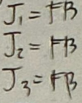
Forward Conducting Region
The operational state of an SCR where the device is forward-biased and conducts current, allowing significant current to flow through the device while it remains in the conducting state.
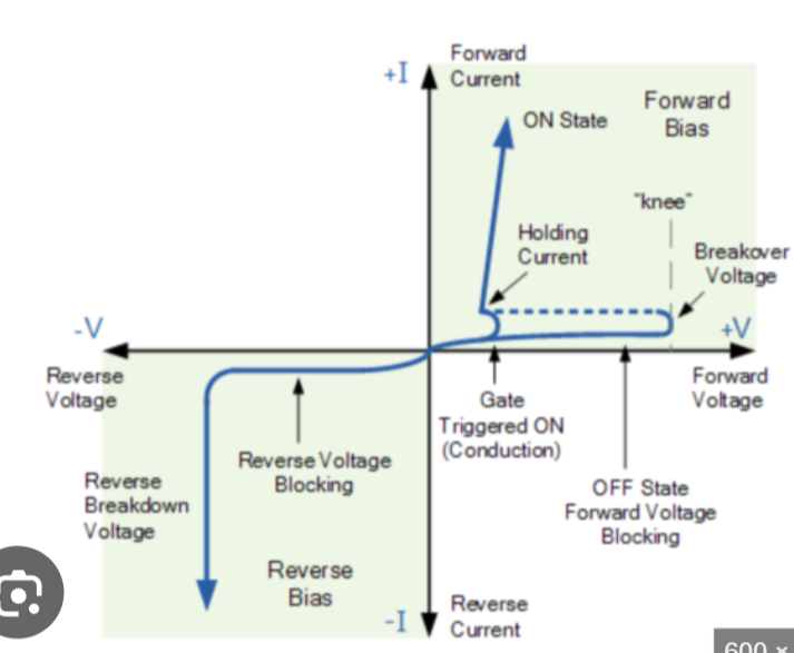
SCR Characteristic Curve
A graph representing the current and voltage characteristics of a Silicon Controlled Rectifier (SCR) across its various operational regions, including forward blocking, reverse blocking, and forward conducting.
Turning Off SCR methods
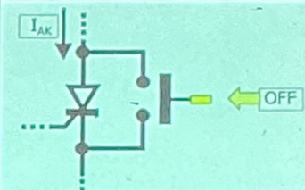
Anode Current Interruption
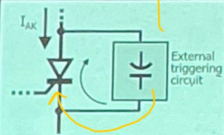
Forced Commutation
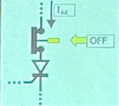
Anode Current Interruption
process of reducing the current flowing through the anode of a thyristor (SCR) to below its holding current
Series Interruption
Normally closed configuration of Anode Current Interruption
Shunt Interruption
Normally open configuration of Anode Current Interruption
Forced Commutation
process of turning OFF a Silicon Controlled Rectifier (SCR) in a DC circuit by using an external circuit (using capacitors, inductors, auxiliary SCRs, or switches) to force the anode current to zero or below the holding current



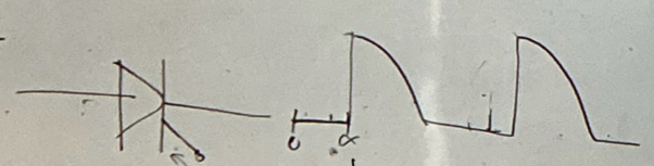
Firing angle
angle measured from the zero-crossing of the AC voltage to the instant an SCR (Silicon Controlled Rectifier) is triggered ON by a gate pulse.
In an AC circuit, the voltage is sinusoidal. Even though the SCR becomes forward-biased at the beginning of each positive half-cycle, it does not conduct immediately. It starts conducting only when a gate pulse is applied.
dv/dt Triggering Method
The SCR is forward-biased but OFF.
The anode-to-cathode voltage rises very rapidly (high dv/dtdv/dtdv/dt).
The SCR's internal junction capacitance charges, producing a charging current.
If the charging current is large enough, it acts like a gate current.
The SCR turns ON without a gate pulse (unwanted triggering).
Temperature Triggering Method
unintentional turning ON of a Silicon Controlled Rectifier (SCR) due to a high junction temperature, even without applying a gate pulse.
As the SCR's temperature increases:
More electron-hole pairs are generated inside the semiconductor.
The leakage current across the SCR increases.
If the leakage current becomes large enough, it acts like a gate current.
The SCR turns ON without any gate signal
Forward voltage triggering method
process of turning ON an SCR by increasing the forward anode-to-cathode voltage until it reaches the breakover voltage (VBO), even without applying a gate pulse.
Snubber circuit (RC snubber)
used to protect an SCR from unwanted dv/dt triggering.
low firing angle value
output of SCR is increased, turning on is faster
high firing angle value
output of SCR is decreased, turning on is slower
Latching Current (IL)
The minimum anode current required immediately after triggering to keep the SCR ON when the gate signal is removed.
Holding Current (IH)
minimum anode current required to keep the SCR conducting. If the current drops below this, the SCR turns OFF.



SSSGDT

4-pin device which is an SCR plus another external terminal, connected to the base of the top resistor and the collector of the bottom transistor
Used for faster switching time
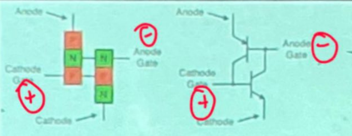
Schematic diagram of SCS
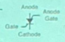


schematic symbol of GTO
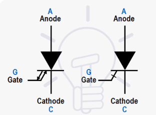
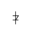
Shockley Diode / Latching Diode
The device is turned on using the Forward Breakover Voltage

Schematic symbol of Shockley Diode
DIAC
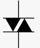
Shockley diode that is back-to-back
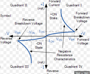
It is a full-wave or bi-directional semiconductor switch that can be turned on in both forward and reverse polarities
DIAC characteristic curve
Schematic symbol of DIAC
5 - 30us
Typical turn off time of SCR in Forced Commutation
Typical Breakover Voltage of DIAC
20-40V
Typical Breakover Current of DIAC
50 - 200uA
TRIAC
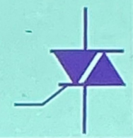
SCR that is back-to-back

Schematic symbol of TRIAC
TRIAC characteristic curve
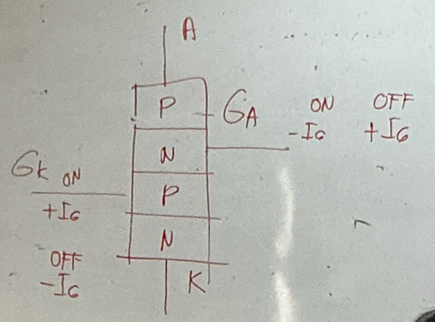
Apply a negative pulse to CG or a positive pulse to AG

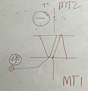
Quadrant IV (MT2 negative, gate positive)

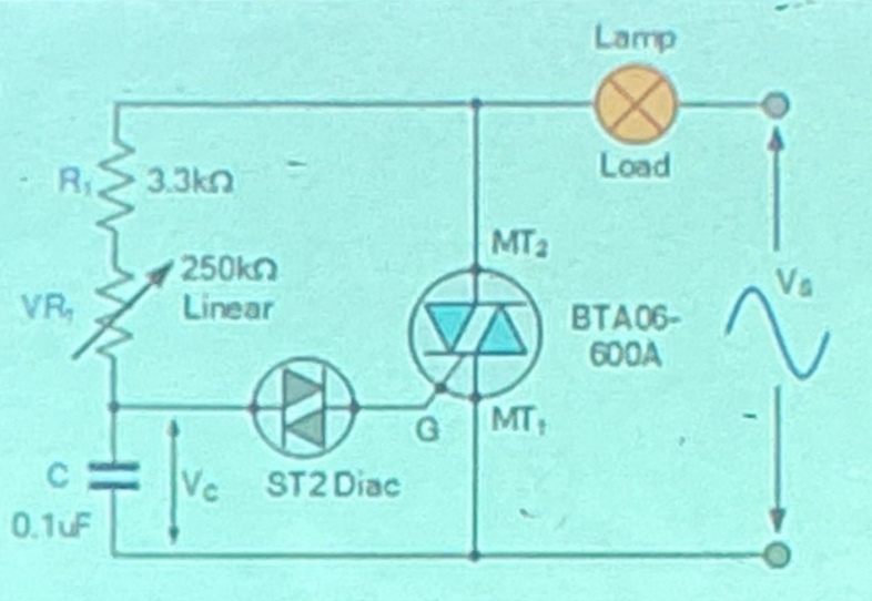
Household light dimmer switches
Most common real-world application for a TRAIC and DIAC combination circuit
DIAC are specifically designed to trigger
TRIAC and SCR
saka lang matrigger yung DIAC if naabot na ang time constant RC
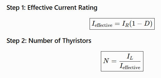
% derating of thyristor
means you do not use the thyristor at its full rated current. Instead, you use only (100% - % derating) of its rated current for safe operation.
number of thyristors required formula
D - derating
IL - load/circuit current rating
PIV (Peak Inverse Voltage)
maximum reverse voltage that a diode, SCR, or thyristor can withstand in the OFF state without breaking down
PIV formula for Half-wave and Bridge rectifier/SCR/thyristor

PIV formula for Full-wave


Field of electronics that deals with the generation, detection and control of light using electronic devices, particularly semiconductors.
Converts electricity to light and vise versa

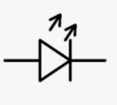
two-lead semiconductor devices that are similar to normal diodes except that they emit light that can be visible, infrared, or ultraviolet.
LED schematic symbol
Characteristics of GaAs LED

Characteristics of GaAsP LED lower Vf

Characteristics of GaAsP LED higher Vf

Characteristics of GaAsPN LED

Characteristics of AlGaP LED

Characteristics of SiC LED

Characteristics of GalnN LED

injection laser or diode laser
semiconductor device that emits coherent light when an electrical current is passed through it.
LASER meaning
Light Amplification by Stimulated Emission of Radiation
Coherent light emitted by LASER
Monochromatic (same wavelength), same phase, same time
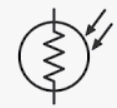
Photoresistors / light dependent resistors (LDRs)
electronic component whose resistance changes depending on the amount of light falling on its surface.
@ dark = resistance is high
@ illumination = resistance drops
Photoresistors / light dependent resistors (LDRs) schematic symbol
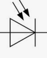
Photodiodes
two-lead semiconductor devices that convert light energy (i.e., photons) directly into electric current
constructed using a very thin n-type semiconductor together with a thicker p-type semiconductor.
Photodiodes schematic diagram
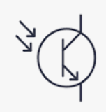
Phototransistors
a type of transistor that operates by using light to control the flow of current between its emitter and collector
It's a semiconductor device that converts light signals into amplified electrical signals.
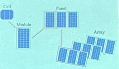
Solar Cells
These are simply photodiodes with exceptionally large surface areas.
These larger areas allow the them to be more sensitive to incoming light as well as more powerful, in terms of both voltage and current, than photodiodes.
Commonly used in solar panels, but they are also often used as light-sensitive elements in detectors of visible light.
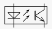
Optoisolator / optocoupler / photocoupler,
an electronic component that transfers electrical signals between two circuits using light.
It provides electrical isolation, meaning it prevents direct electrical connection between the circuits while still allowing signal transfer.
LED + phototransitor
Optoisolator / optocoupler / photocoupler schematic symbol


@Rayleigh Scattering, ↑frequency = ↑attenuation. So with infrared with less f then lower loss

Transducers
• Devices that convert one form of an energy to another.
- They also convert non-electrical quantity to an electrical form.
• Categories include resistive, capacitive, inductive, piezoelectric, optical, and digital transducers.
Range [Selection of Transducers]
Should be large enough to encompass all the expected magnitude of the measured (measuring range covers every value you expect to measure.)
Sensitivity [Selection of Transducers]
should give a sufficient output signal per unit of measured input to yield meaningful data.
Sensors
Converts any energy into electrical signal
Actuators
Converts electrical energy into any energy
Electrical output characteristics [Selection of Transducers]
(e.g. the output impendence, frequency response and response time) of the output signal should be compatible with the recording devices and the rest of the measuring system equipment.
Physical environment [Selection of Transducers]
Should be able to withstand the environment conditions to which it is likely to be subjected while carrying out measurements and test.
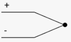
Thermocouples
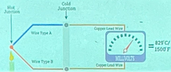
a temperature sensor that generates a voltage based on the temperature difference between two dissimilar metal wires joined together.
Thermistor schematic symbol
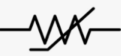
Thermistor
a type of variable resistor whose resistance changes significantly with temperature.
These devices are commonly used for temperature sensing and control in various applications.
Plezoelectric crystal microphone
an active transducer that generates its own electrical output without needing an external battery
Seebeck Effect
A thermocouple is a temperature transducer made by joining two different metals. It operates based on this, which generates a tiny voltage proportional to the temperature difference between the junctions.
Negative Temperature Coefficient (NTC) thermistor
temperature increases, decrease resistance
resolution of a transducer
The smallest detectable change in the Input that causes change in the output
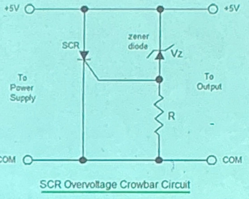
Crowbar
A circuit that protects a sensitive circuit from a sudden increase in supply voltage
Programmable Logic Controllers
is a special form of microprocessor-based controller that uses a programmable memory to store instructions and is designed to be operated by engineers with perhaps a limited knowledge of computers and computing languages.
ladder programs
pre-programmed programmable logic controllers so that the control program can be entered using a simple pictorial form of language
Five Basic Components of PLC
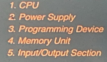
Central Processing Unit CPU
unit containing the microprocessor and this interprets the input signals and carries out the control actions, according to the program stored in its memory, communicating the decisions as action signals to the outputs.
Power Supply
needed to convert the mains a.c. voltage to the low d.c. voltage (5 V) necessary for the processor and the circuits in the input and output interface modules.
Programming Device
used to enter the required program into the memory of the processor.
The program is developed in the device and then transferred to the memory unit of the PLC.
Memory Unit
where the program is stored that is to be used for the control actions to be exercised by the microprocessor
Input/Output Section
where the processor receives information from external devices and communicates information to external devices.
The inputs might be from switches, temperature sensors, or flow sensors, etc. combined with appropriate signal processing elements.
The outputs might be to motor starter coils, solenoid valves, etc.
Counter
If you want a conveyor belt to stop exactly 10 seconds after a box passes a sensor, what basic instruction do you add to the program?
Scan cycle
process in which a PLC continuously reads input signals, executes the control program, and updates the output signals in a cyclical manner
Sequential logic control
primary application of Programmable Logic Controllers (PLCs) in industrial automation
UJT Unijunction Transistor
non-linear amplifiers so it is used as switch
known for negative resistance since RB1 is decreasing overtime
intrinsic stand-off ratio is non-changing