Unified Modelling Language (UML) Diagrams
1/15
Earn XP
Description and Tags
Some flashcards on what UML is and how to read and create UML class diagrams (with the focus on Java). I also touch on the different types of relationships between classes.
Name | Mastery | Learn | Test | Matching | Spaced | Call with Kai |
|---|
No analytics yet
Send a link to your students to track their progress
16 Terms
UML: Overview
UML is a language-independent way of modelling systems of classes and objects within your program. There are different types of UML Diagrams:
Class diagrams - Deline the classes and interfaces in a system and their relationships. Can help with building the static view of your programme.
Use case diagrams - Presents the ways in which your system can be used, and the different people and entities that relate to your system.
Sequence diagrams - Shows how the objects talk to eachother (their dynamic relationships) in order to achieve a goal. My module focuses on class and sequence diagrams, so that’s what the other flashcards will focus on.
Classes
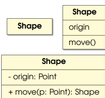
Typically, the first row of the UML Diagram has the class name, the second row has the attributes/variables and the third row ccontains the methods. As you can see in the image, the level of detail in a class “block” might vary depending on the stage:
- If the details of a class are in another diagram, having the name alone is fine.
- Else, at the analysis stage you don’t need the types.
- At the design state, you want the visibility (public, private, protected) and the types of attributes included.
Abstract classes have their class name in italics. This also applies to methods. Unless the class is primitive (which wouldnt be included in a UML diagram anyway), class names are denoted with a capital letter.
Representing Fields
Fields are usually denoted in this order
- (visibility) name : type (multiplicity in brackets) = defaultValue
For example, you might have a field of “private static int count = 50; with a multiplicity of 1 or more”
This would be represented as
- count: int(1..*) = 50;
Where the minus sign represents the visibiltiy (minus sign is private, plus sign is public and pound/hashtag (whatever you call #) is for protected). After that is the name of field, followed by a colon, followed by the field type, and then the multiplicity (always in brackets). This follows an equals sign and finally the default value. Static fields are represented by being underlined.
Representing methods
Method follow most of the same rules as Fields, but with a few extras:
- (visibility) name (parameter1 in brackets, : (type), parameter2(if there are any parameters) in the same brackets : type) : (return type). If there is no return type, leave this part out
For example, “public int addition(int num1, int num2)”"
Would look like this in uml
+ addition(num1: int, num2: int) : int
Representing Interfaces
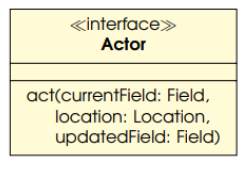
Interfacs are represented similarly to classes but typically include only abstract methods. Their structure consists of + (visibility) name (parameter1 : type, parameter2 : type) without return types, focusing on providing behavior without implementation.
Interfaces can include fields if (and only if) they are private static and final. Above the interface name is the word Interface surrounded by guillemet brackets. (« interface »)
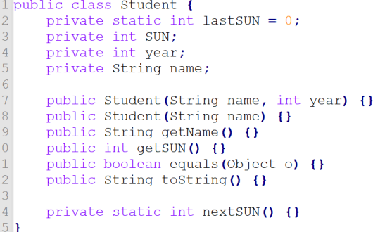
Exercise: Translate this to UML
Answer:
Row 1: Student
Row 2: - lastSUN: int = 0
- SUN: int
- year: int
- name: String
Row 3: + Student(name: String, year: int)
+ Student(name: String)
+ getName(): String
+ getSUN(): int
+ equals(o: Object): booelan
+ toString(): String
- nextSUN: int
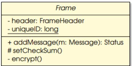
Exercise: Translate this to Java
Answer:
public abstract class Frame {
	private FrameHeader header;
	private static long uniqueID;

	public Status addMessage(Message m){}
	protected void setCheckSum(){}
	private void encrypt(){}
}Relationships
A connection between two or more UML elements, defining how they interact or are associated with one another, such as associations, dependencies, generalisations, and realisations.
Generalisation Relationship - Extends
This is when a class extends another class. It represents an inheritance relationship where a subclass inherits attributes and methods from a superclass. It is defined in UML Diagrams using a hollow triangle arrow pointing from the subclass to the superclss. As mentioned before, you can use generalisation between interfaces, but interfaces can’t extend classes (even abstract ones).
Realisation Relationship - Implements
This is a relationship where a class implements an interface, providing the actual behavior defined by the interface. In UML diagrams, it is represented by a dashed line with a hollow triangle pointing from the class to the interface.
Association Overview
Association in general is just a reference from objects in one class to another class, indicating a relationship where one class uses or interacts with another. However, you can have two more specific forms of association - composition and aggregation.
Association Relationship - Aggregation
Represented in UML Diagrams using a white diamond on the “whole” side. It signifies a "whole-part" relationship, where the part can exist independently of the whole. It implies a stronger relationship than simple association but weaker than composition.
I’ll try to break this down with an example. Imagine a library filled with books. If the library was taken apart, the books could still exist independently, illustrating the aggregation relationship. Similarly , an aggregation relationship can be illustrated between a department and its employees, where employees can exist without being tied to a specific department. In those two examples, the library and the department are the “whole”entities, while the books and employees are the "parts" that can exist independently.
Association Relationship - Composition
Represented in UML diagrams using a black diamond on the "whole" side, composition signifies a strong "whole-part" relationship where the part cannot exist independently of the whole. If the whole is destroyed, the parts are also destroyed.
An example of this is a university and its courses. As a university determines the structure and content of the courses, if the university is destroyed, the courses are destroyed too. Another example can be a house and its rooms; if the house is demolished, the rooms cease to exist.
Multiplicity
Used to add further definition to the relationship of two objects. By default, no specified multiplicity means a multiplicity of 1. A few examples:
0..1 means Zero or One
2..* means two or many.
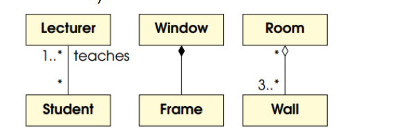
In the images, the first one reads as Lecturer teachers (many) students, student is taught by or many Lecturers. The multiplicity is usually opposite to the class it talks about. For the last one, it would be Room is made up of (then read the multiplicity opposite room) 3..* 3 or more Walls
and Wall makes up many Rooms.
Dependency
A dependency in UML diagrams signifies a relationship where one element relies on another element for its specification or implementation. It indicates that changes in the independent element can impact the dependent element, often represented by a dashed arrow pointing from the dependent to the independent element.
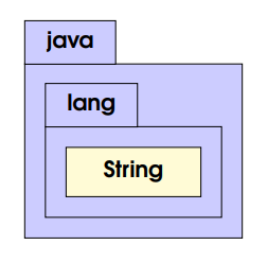
Packages
Look file a folder of tabs. May just have a simple name or their full name.