Private Pilot 1
1/49
Earn XP
Description and Tags
Outside and Inside the Airplane
Name | Mastery | Learn | Test | Matching | Spaced |
|---|
No study sessions yet.
50 Terms
Go-No-Go
A decision-making process used by pilots to determine if weather conditions or other factors are satisfactory for a flight to proceed. It ensures safety and compliance with regulations before takeoff.
Summer Weather Adv/Dadv
Often offers warm and flyable days. Advisories indicating potential hazards such as thunderstorms, turbulence, or visibility issues during the summer flying season.
Winter Weather Adv/Dadv
Provides clearest air and peak aircraft performance due to cold dense air. Advisories that inform pilots of potential hazards related to winter flying conditions, including snow, ice, low visibility, and strong winds.
For VFR training, what is the minimum practical visibility?
3 miles. Preferable to fly in better conditions tho.
What is the VFR ceiling height minimum?
1,000 feet above ground level (AGL)
What does “ceiling” mean in cloud terms?
The lowest cloud layer covering the sky
What does “overcast” mean in cloud terms?
The sky is completely covered with clouds “overcast ceiling”
What does “broken” mean in cloud terms?
“broken ceiling” indicates an overcast with some breaks or holes in the clouds
What are the Four Forces of flight?
Lift, Weight, Thrust, Drag
What is lift?
Force that acts upwards against weight, produced by wings
What is weight?
Force by gravity acting downward
What is thrust?
Propels the plane forward, produced by engine and propeller
What is drag?
Force acting opposite to thrust, caused by air resistance
What is Bernoulli’s Principle?
(Lift) If the speed of a gas/fluid is increased, there will be a decrease in pressure
How does wing shape create lift?
The upper surface is curved (camber), the lower surface is relatively flat. The airflow of the top speeds up, decreasing pressure and creating lift
What is Newton’s 3rd Law?
(Lift) For every action, there is an equal and opposite reaction. Air striking the bottom of the wing is deflected downward = the wing pushes the air down/the air pushes the wing up
What is Total Lift?
Combination of decreased pressure on top and increased pressure below the wing
What are the 5 key wing parts?
Leading Edge (Front of wing)
Trailing Edge (Back of wing)
Chord Line (Imaginary line from leading to trailing edge)
Upper Camber (Top curve of wing)
Lower Camber (Bottom curve of wing)
Longitudinal (Long) Axis Movement & ‘Location’?
(Roll) Runs lengthwise thru the fuselage, movement around this axis is called bank or roll

Lateral Axis Movement & ‘Location’?
(Pitch) Passes thru the wings, side to side, movement around this axis is called pitch
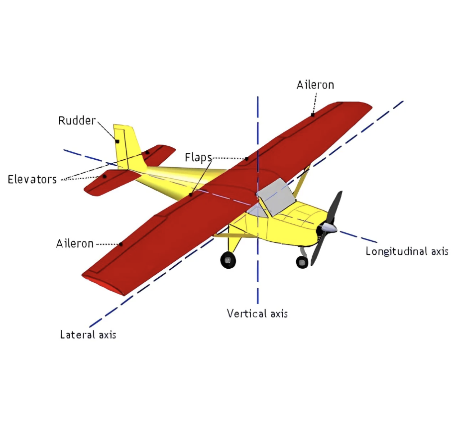
Vertical Axis Movement & ‘Location’?
(Yaw) Runs vertically through the center of gravity, movement around this axis is called yaw

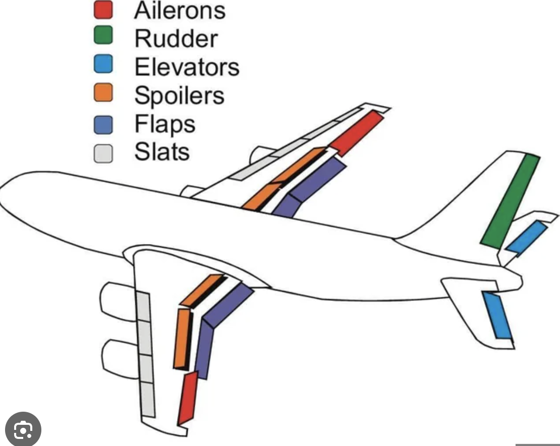
Elevator
Controls pitch (movement around the lateral axis).
Operated by pushing or pulling the yoke.
Pulling back moves the elevator up, pitching the nose up.
Pushing forward moves the elevator down, pitching the nose down.

Ailerons
Located at the outboard ends of the wings.
Control roll (movement around the longitudinal axis).
Operated by turning the yoke left or right.
Turning yoke right raises right aileron, lowers left aileron; airplane banks right.
Turning yoke left raises left aileron, lowers right aileron; airplane banks left.

Rudder
Controls yaw (movement around the vertical axis).
Operated by pressing the rudder pedals.
Pushing right pedal moves rudder right, yawing nose right.
Pushing left pedal moves rudder left, yawing nose left.
Used primarily to counteract adverse yaw during turns.
Adverse Yaw
Occurs when deflecting ailerons during turns.
Down aileron increases lift and drag on that wing.
This causes the airplane to yaw opposite the turn direction.

Coordination with Rudder
Rudder input counters adverse yaw.
Ensures smooth, coordinated turns.
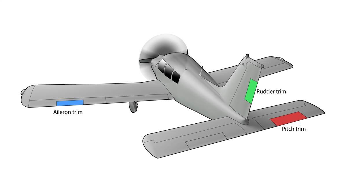
Trim Tabs
Used to relieve control pressure on primary control surfaces.
Attached to trailing edge of elevator, sometimes rudder.
Elevator trim adjusted in flight; rudder trim often ground-adjustable.
Flaps
Located on the inboard trailing edge of wings.
Both flaps extend and retract simultaneously.
Lowering flaps increases wing chord and camber.
Increases both lift and drag.
Allows for steeper, slower approaches during landing.
Can be used to shorten takeoff distance.

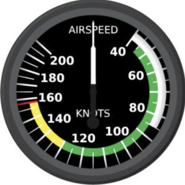
Airspeed Indicator
Measures speed in knots (nautical miles per hour).
Speed ranges and limitations are marked:
Red line: Never exceed speed.
Yellow arc: Caution range (smooth air only).
Green arc: Normal operating range.
White arc: Flap operating range.
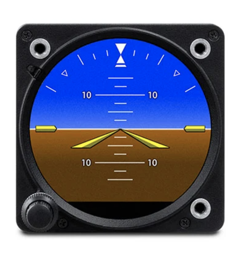
Attitude Indicator
Uses a gyroscope to stabilize a horizon bar.
Displays pitch and bank relative to the natural horizon.
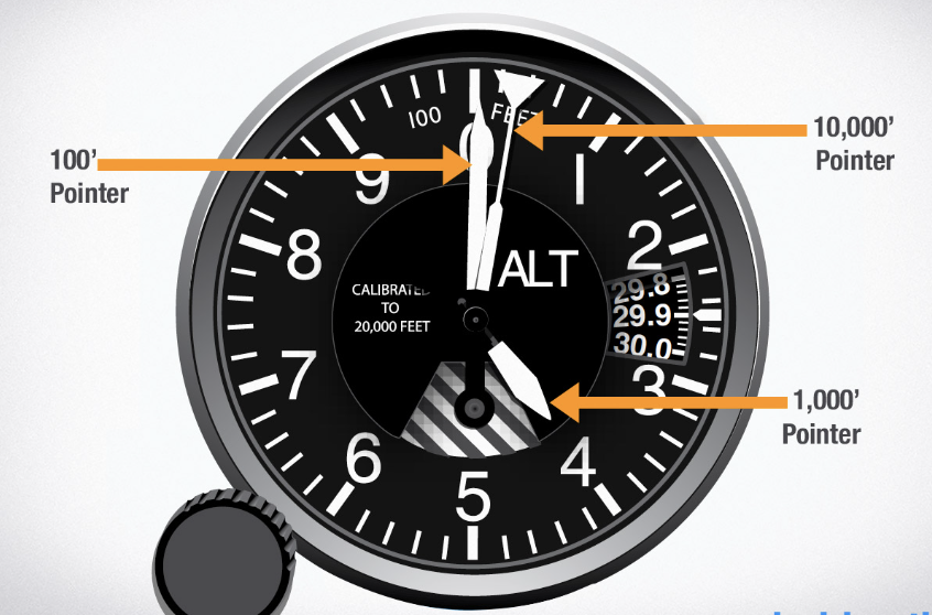
Altimeter
Measures altitude above sea level.
Uses rotating hands similar to a clock:
Short hand: Thousands of feet.
Long hand: Hundreds of feet.
Diamond-shaped indicator: Tens of thousands of feet.
Must be set prior to every flight due to changing barometric pressure.
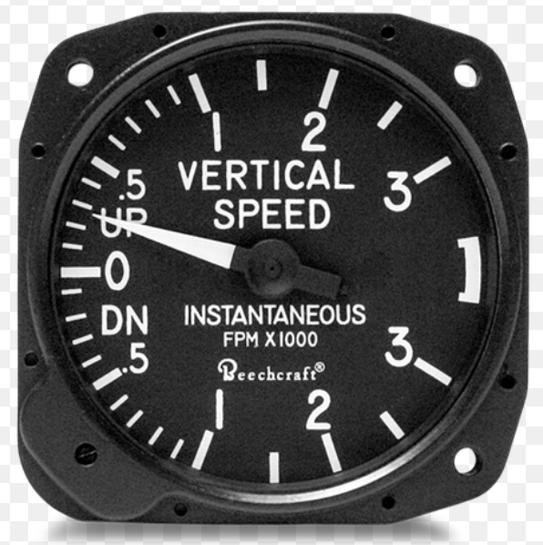
Vertical Speed Indicator (VSI)
Measures rate of climb or descent in feet per minute.
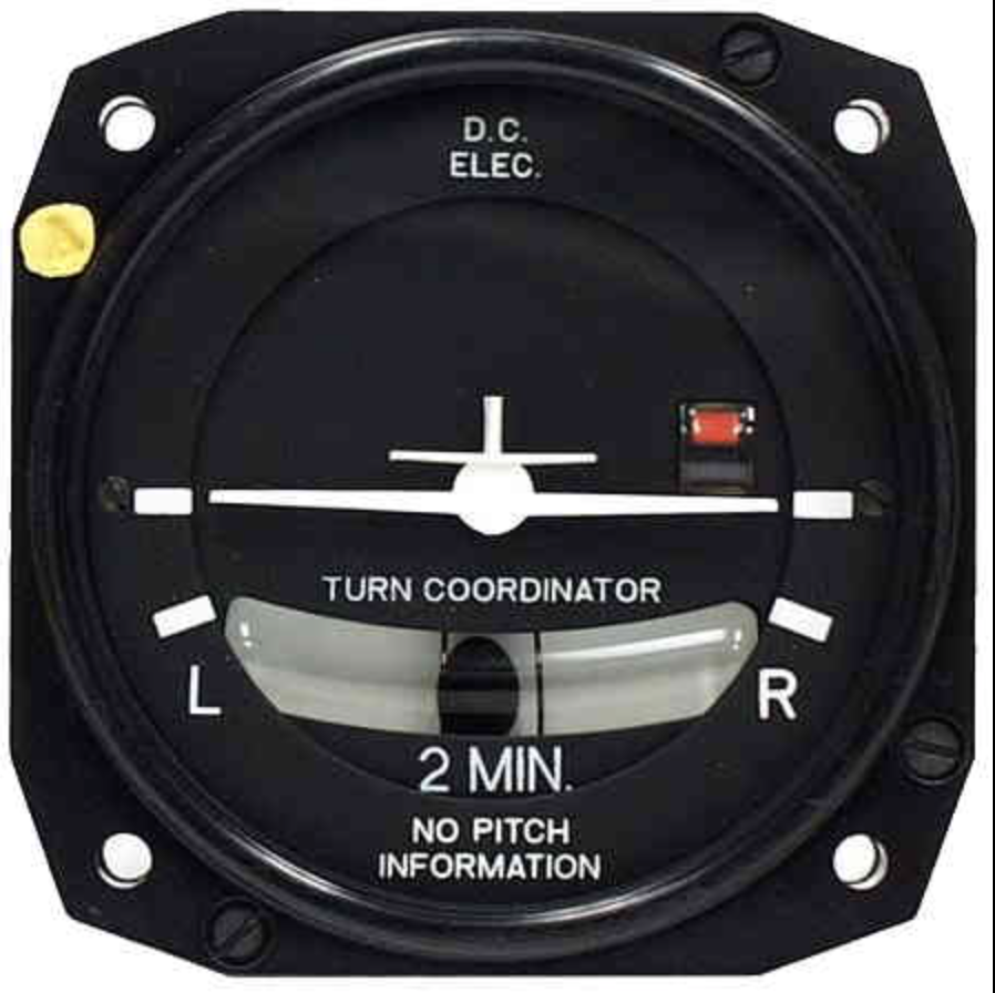
Turn Coordinator
Provides information about direction and rate of turn.
Inclinometer (ball) shows quality of the turn (coordination).
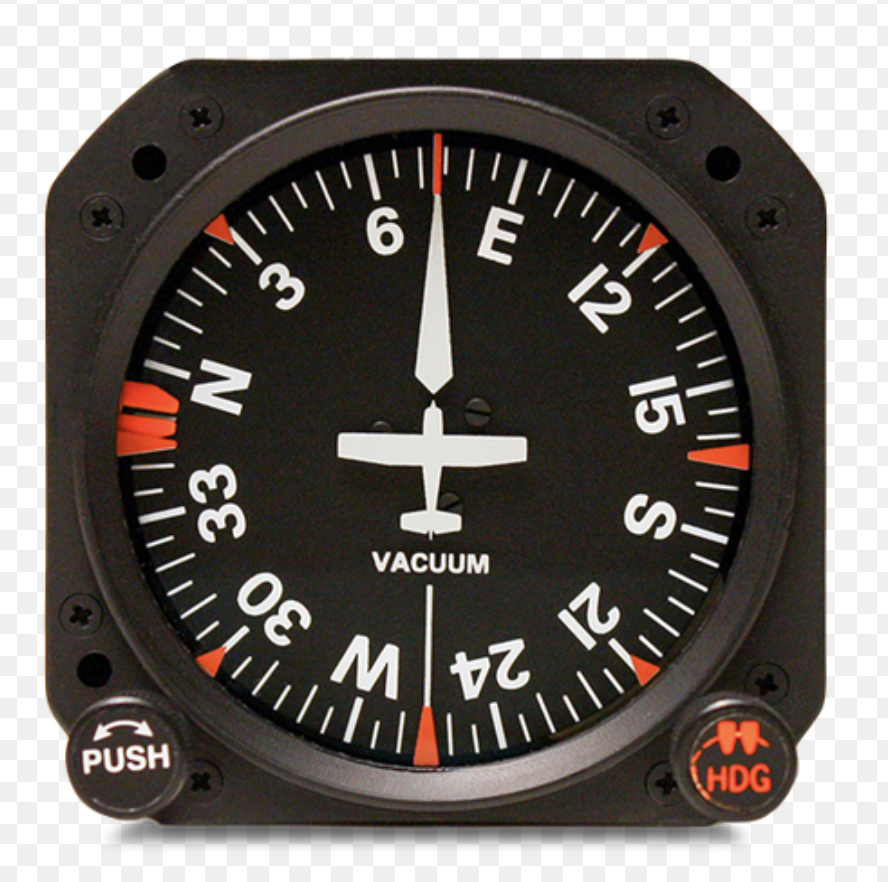
Heading Indicator (Directional Gyro)
Main directional instrument used in flight.
Gyroscopically stabilized; not affected by banks, turns, or speed changes.
Must be set to the compass before takeoff and adjusted during flight.
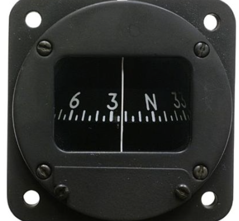
Magnetic Compass
Shows aircraft heading relative to magnetic north.
Affected by banks, turns, and speed changes; used in conjunction with the heading indicator.
Throttle
Controls engine power by regulating airflow into the engine.
Push forward to increase power; pull back to decrease.
Throttle friction lock adjusts ease of movement.
(Engine Controls)
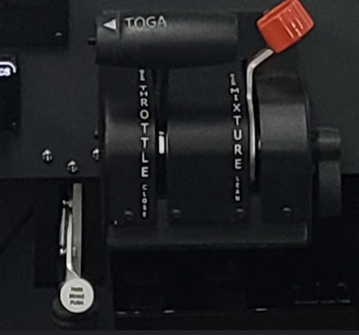
Mixture Control
Regulates fuel-to-air ratio.
Push forward to enrich mixture; pull back to lean.
(Engine Controls)

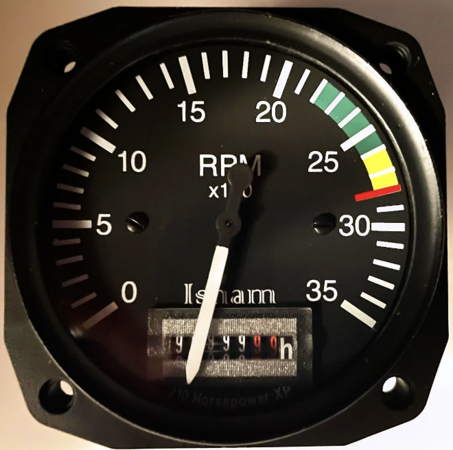
Tachometer
Indicates engine RPM (revolutions per minute).
Marked to show maximum permissible RPM.
(Engine Instruments)
Oil Pressure and Temperature Gauges
Monitor engine health and operation.
Fuel Flow Gauge
Shows fuel consumption in gallons per hour.
Exhaust Gas Temperature (EGT) Gauge
Helps in setting the proper mixture.
Flap Control
Controls the position of wing flaps.
Positions at 10°, 20°, and 30°.
Elevator Trim Control
Adjusts the neutral position of the elevator to relieve control pressure.
Rotate forward for nose-down trim; aft for nose-up trim.
Fuel Selector
Selects fuel tank(s):
Left tank, right tank, or both.
Includes a separate fuel shutoff valve.
Vacuum Gauge
Monitors the operation of engine-driven vacuum pumps powering gyroscopic instruments.
Electrical System:
Switches and circuit breakers for electrical components
Voltmeter, Clock, and Outside Air Temperature Gauge
Important for navigation and weather considerations.
Primary Flight Display (PFD)
Displays flight instruments digitally.
Large attitude indicator across the screen.
Airspeed indicator on the left as a digital tape.
Altimeter on the right as a digital tape.
Vertical speed indicator and heading indicator also displayed.
Multi-Function Display (MFD)
Shows engine instruments and GPS moving map.
Engine instruments displayed on the left side.
GPS moving map aids in navigation and flight planning.
Integrated Communication and Navigation Radios:
Located at the top of both PFD and MFD.
Operated through the digital interface