materials graphs
1/73
There's no tags or description
Looks like no tags are added yet.
Name | Mastery | Learn | Test | Matching | Spaced | Call with Kai |
|---|
No analytics yet
Send a link to your students to track their progress
74 Terms
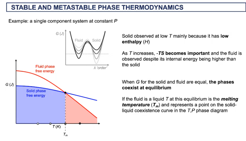
T- P diagram for free energy
below where the lines cross, we get a solid
the minimum of the solids is lower than minimum of fluid
when solid melts, heat is added = heat of fusion
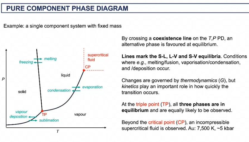
features of phase diagram
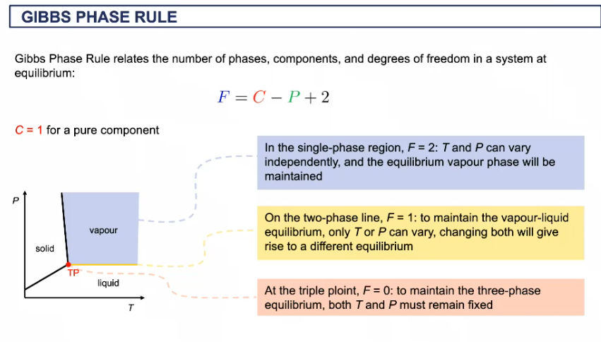
Gibbs phase rule
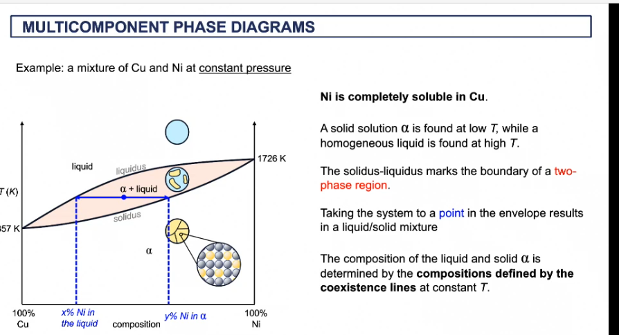
multi component phase diagram
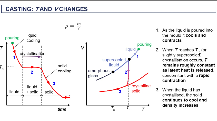
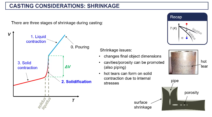
T a d V changes when casting
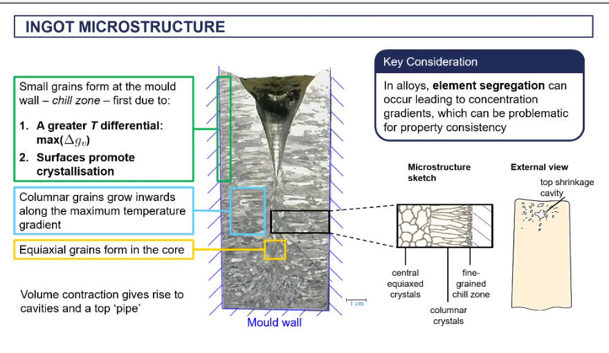
microstructure of an ingot
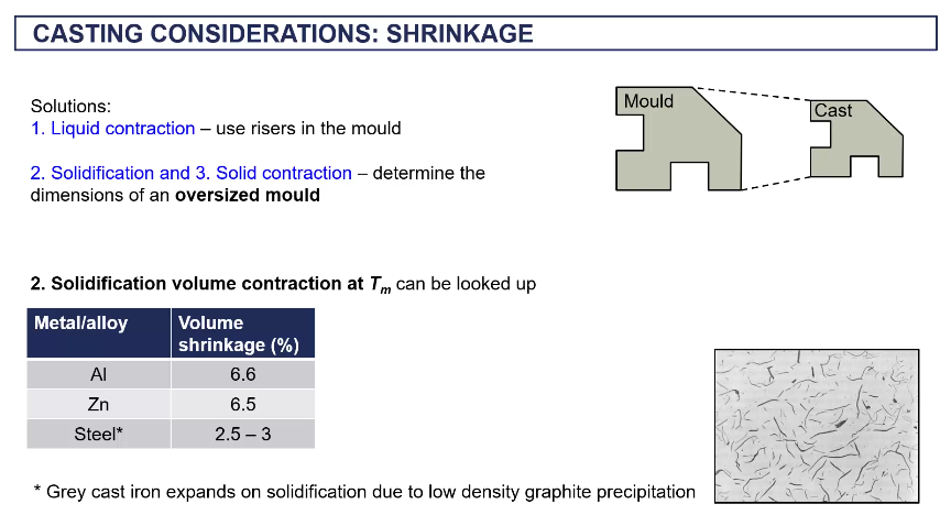
shrinkage in casting
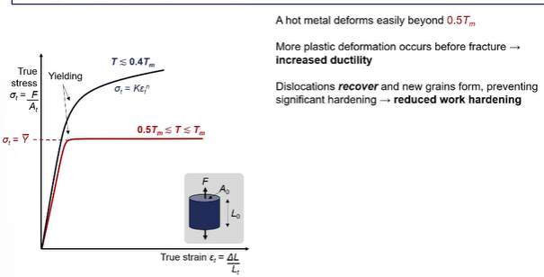
true stress strain curves
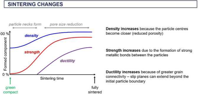
sintering chnages graph
going from green compact from left to fully sintered on right
as we heat it up the the neck starts to form and particle centers become closer together
as you are forming you wan to reduce the surface area to volume ratio
the particles become closer together when sintering, which reduces pore size that increases density (which gets the blue curve)
strength will increase alot as you are creating metallic bonds (red curve)
as you fuse the particle together and the size of those neck regions increases, you are forming more metallic bonds therefore the strength goes up
goes from breaking easily in the hand (the green sand state) to quire strong
ductility won’t increase until you start to create metallic bonds between the adjacent particles
what happens when creating the metallic bonds = allowing the metallic plastic deformation to propagate through the particles, so you can’t have movement of slip planes or dislocations until you starts to connect those particles in the from the initial powder
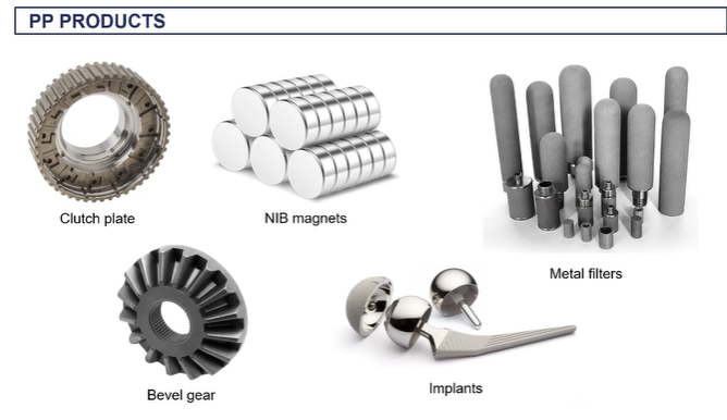
things made from powder processing
processing chnages all the properties, including the mechanical properties
magnetic qulaities increases as you do powder processing as the graisn align when fomring the kneck areas. youre soing recrystallisation, so they become magnetic as you do the sintering process
metal filters are porous
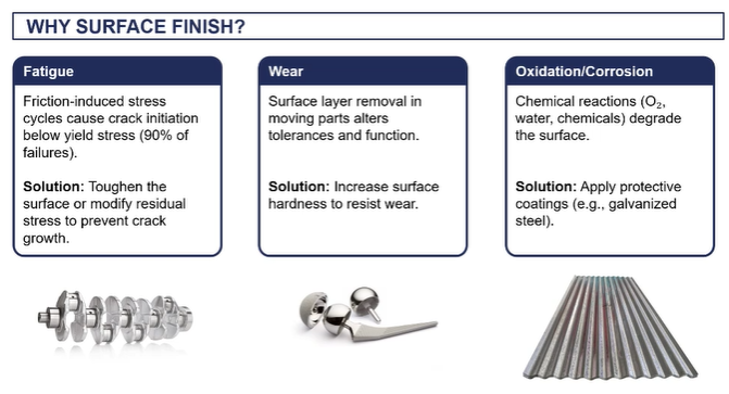
why chnage the surface finish
want to make the surface fatigue resistant as object is exposed to lots of friction/ lots of cyclic loading, therefore we can induce the formation of crack over time
(not accessed on galvanisng/ surface coastings)
surface finishing
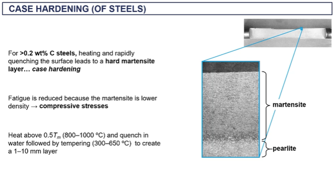
case hardening - thermal
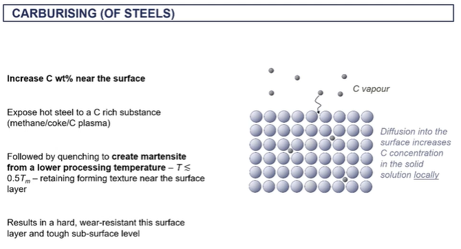
carburizing - thermochemical
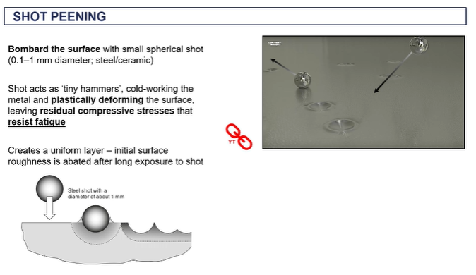
shot peening - mechanical
anodizing - electrochemical
case hardening
thermochemical hardening
heating then rapidly quenching = case hardening as it forms martensite
carburising
thermochemical hardening
increasing carbon content in outer surface
done by heating it and then exposing it to carbon rich substance
by increasing carbon content = making a harder layer
if below the recrystallisation temperature and a very high carbon content on the surface you can make martensite = we want to do this below the recystallisation T because we dont want to lose its texture therefore we carborise it instead
gives a hardware resiatnt surface and the tough subsurface layer
shot peening
plastically deforming surface of material
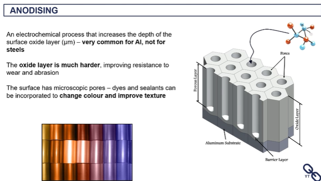
anodising
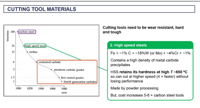
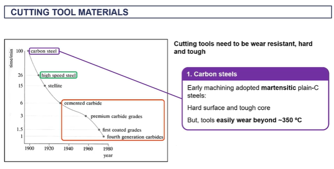
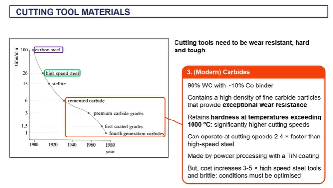
cutting tool materials
modern cutting tools
EXAM - you have a steel, what can you use to cut the steel?
tungsten carbide
because it can withstand very high temperatures up to a thousand degrees C, it's a very hard material.
nd it can it can cut material much faster than alternatives like high speed steels.

why do we do joining?
it's not always easy. It's always economical. It's not always efficient to produce metal objects in their final geometry.
So we need to join, and we need our joints essentially to be, optimised such that they're not going to lead to failure. = not compromising integrity
types of joining (not featured heavility in exam)
fastening
soldering
brazing
welding
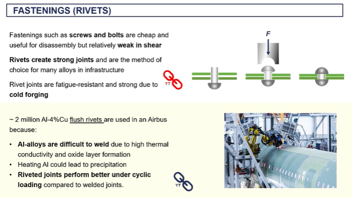
fastening
rivets
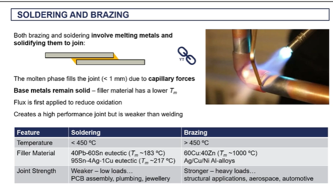
soldering and brazing
soldering is typically done at low temperatures. So less than 450 degrees C is brazing.
in brazing you are usually using brass. brazing makes sotronger bonds over soldering, (baxing used in aerospace)
forge welding - (solid state welding)
What it involves is taking your metals and heating them up to very, very high temperatures far above the recrystallization temperature.
hey're not melting, so you're not reaching the melting temperature, but they're very, very hot. (called being white hot)
when they're at that temperature, you apply very big compressive loads, big passive forces.
Essentially, you're hammering these things together. And in doing so, these high temperatures, with these high pressures
what happens at that interface is atoms and the different metals start to diffuse across the interface. start to create metallic bonds between the two metal objects.
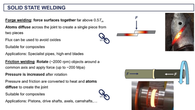
friction welding - (solid state welding)
we're creating extremely high um frictional forces as well as our work force is associated with the the high levels of pressure.
it's giving the atoms enough kinetic energy such that they can diffuse across the interface and form new metallic bonds.
very commercial technique used to formation produce pistons uh camshafts, axles

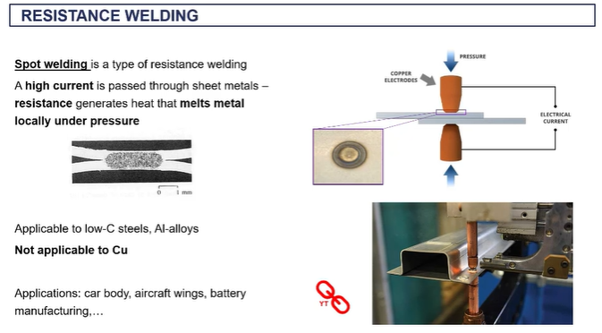
spot welding -(resistance welding)
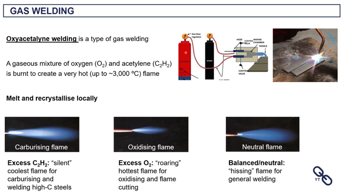
oxycetalyne welding (gas welding)
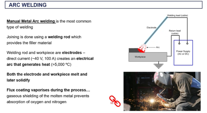
manual metal arc welding (arc welding)
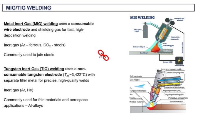
MIG welding
your filler material is on a coil and it's being fed through during the process through this gun.
aimed towards where you want to make the joint the gas is giving you that shield to avoid oxidation and you're getting melting locally to produce your joint there.
o the inert gas is typically all gone if you're dealing with steels
you don't need to apply any flux in this case because you have that in gas.
it's very efficient because you're continually feeding in that wire, that welding material rather than having to take individual rods.

TIG welding
Tungsten and gas is another very, very commercial technique which is more suited to aluminium alloys.
you don't have a consumable welding rod, instead the filler rod is manually on the side
the arc welding is done by connection between the base metal and this tungsten electrode, which is in the gun
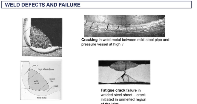
weld heat affected zone
as the heat dissipates throughout the material, depending on the thermal conductivity of that material,
the temperature gradients are going to change as temperature gradients are going to lead to changes in the microstructure.
There's changes in the microstructure are going to lead to changes in the mechanical properties as you go away from this weld joint.
heat will flow into the material and that will be controlled by the thermal diffusivity
So we're going from a very very high temperature. And this rapidly decreases as you move away from the weld
so close to the well joins this what's known as the heat affected zone (heat affected zone is all of this up to up until you get to a microstructure consistent with the base metal,)
next to the wells, you get a, a what they call a green growth zone =where you the metal is beyond the recrystallization temperature/ new grains of nucleated and grown. And they tend to be large grains because that's where, uh, the base metal is the hottest thefore there's enough kinetic energy in time for these grains to grow quite large.
Next to that, you have a recrystallization zone. So again you form new grains.
Nucleation and crystal growth has happened. Um, but this is happening at a lower temperature So you tend to get finer grains
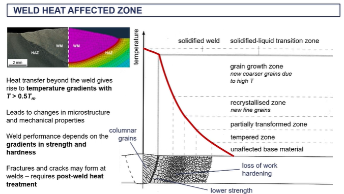
what happens when you have a fast nucleation rate
fast nucleation rate essentially, then you're going to get smaller grains in this region.
weld defects and failure
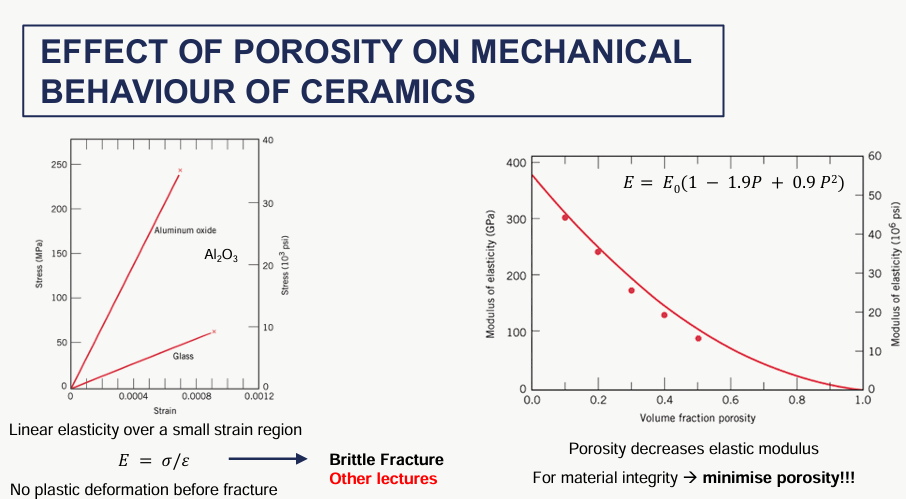
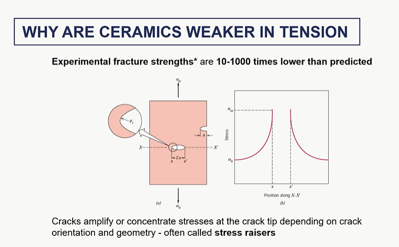
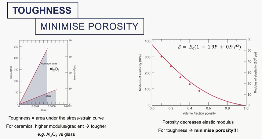
effect of porosity of ceramics on its mechanical behaviour
no plastic deformation before fracture
poisson ratio curve
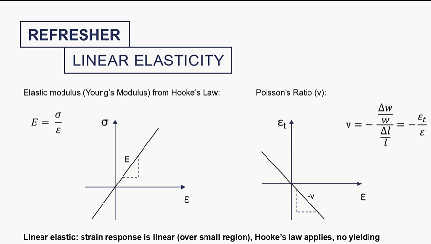
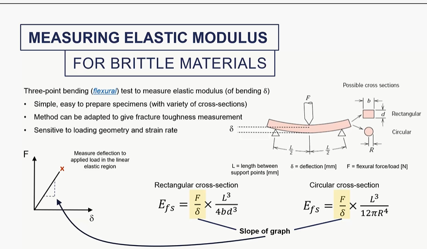
how do we measureelastic modulus for amterials which are weka in tension?
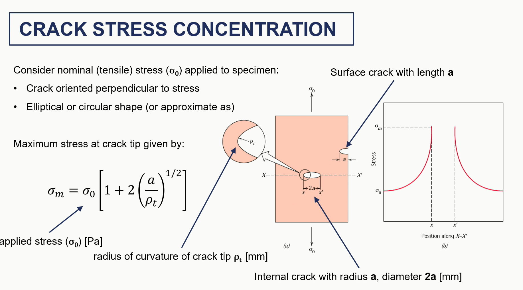
crack stress and propagation graph / assumptions
design to reduce stress crack
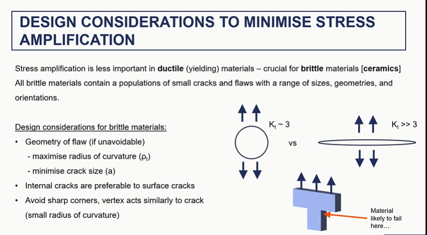
stress raisers
when will fast fracture occur
when a material is at a given stress
crack reaches critical size
stress reaches a critical value
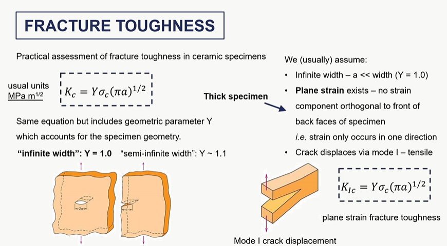
fracture toughness assumptions
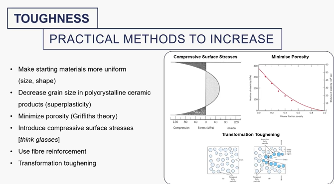
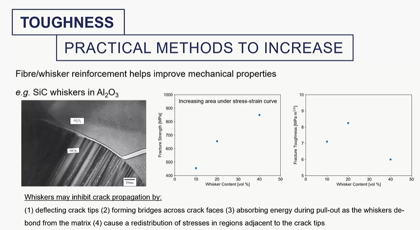
what can you do to increase toughness of materials (particularly ceramics)
toughness graph
toughness = area under the stress strain curve
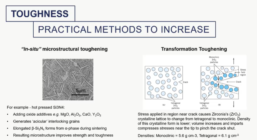
praticle methods to increase toughness
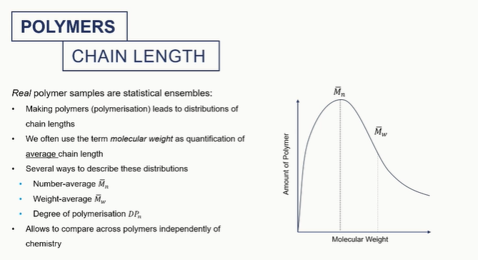
polymer chain graph
this is important as mechanical properties of polymers are dependaent on their molecular weight/polymer size
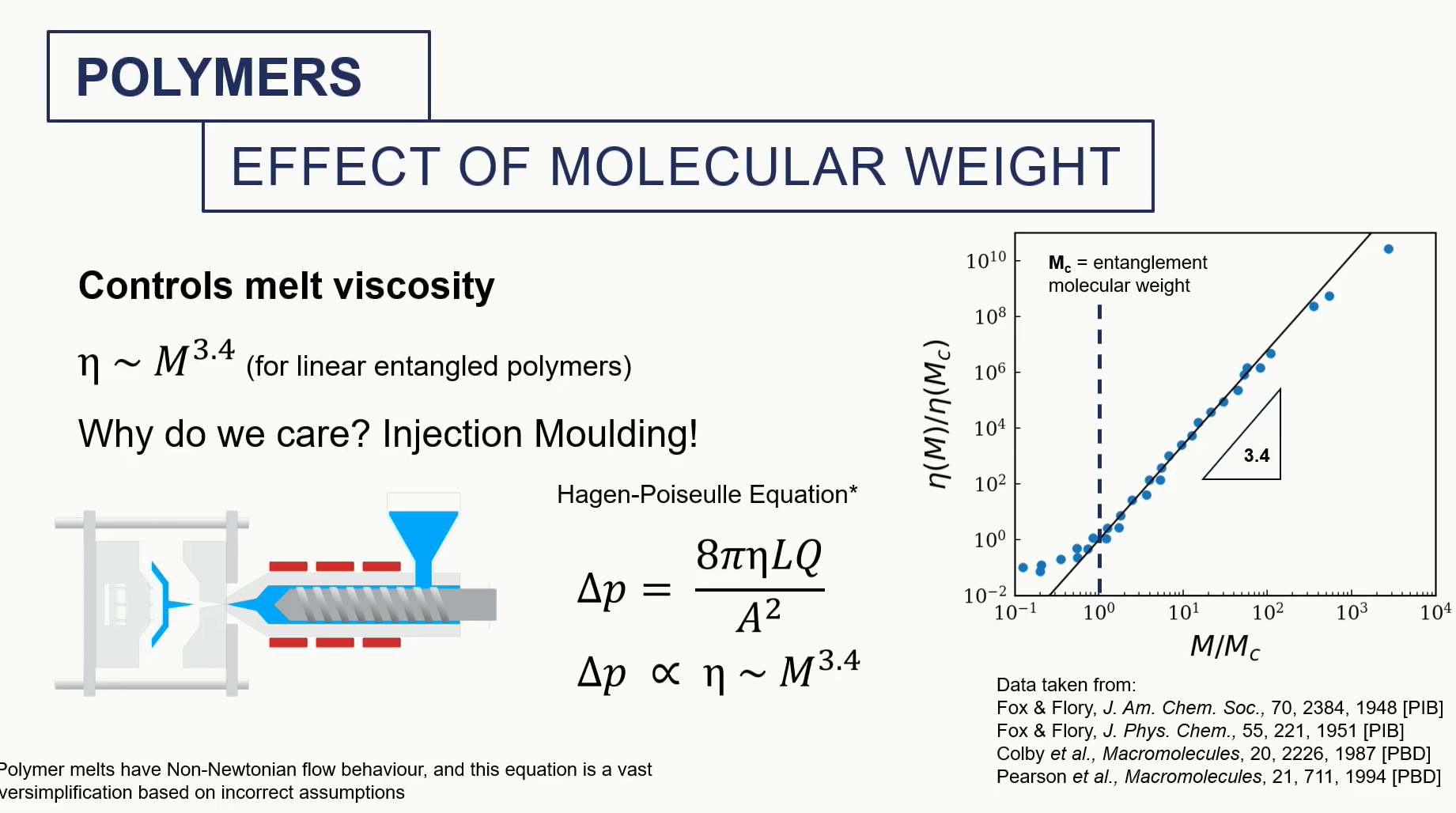
effect of molecular weight (polymer)
we care about this because of the pressurised fluid that needs to be pumped during injection molding, which might be highly viscous
e need to think about how viscous this this solution is to determine how much pressure we need to apply to injecting nothing
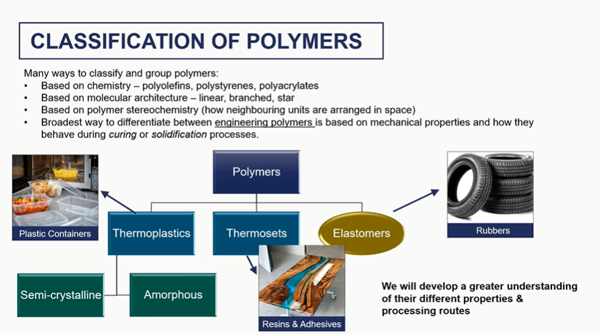
classify polymers the engineering way
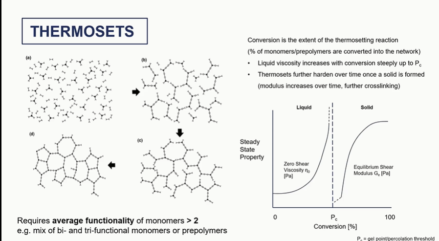
thermosets graph
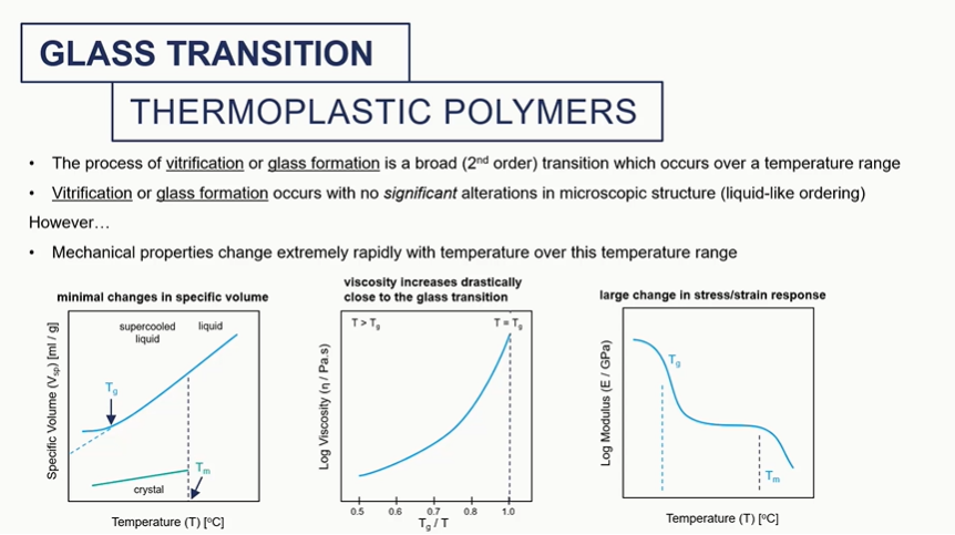
glass tranition graphs
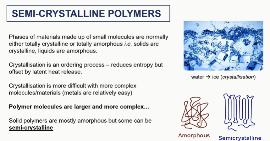
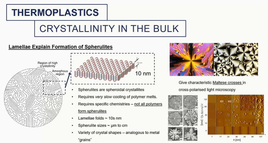
semi crystalline polymers
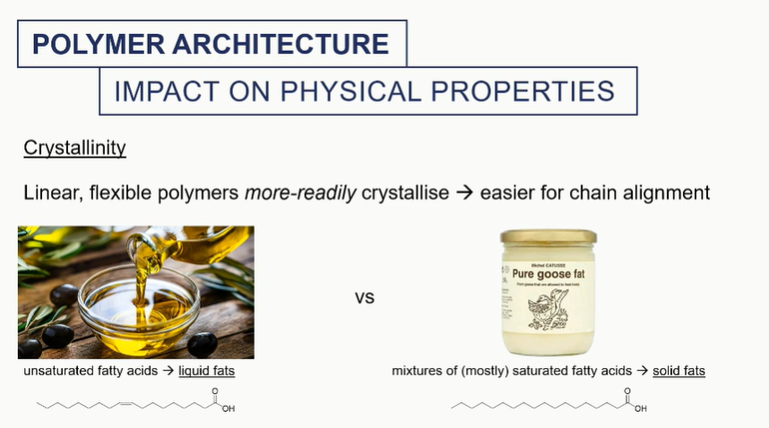
crystallinity
crystallised regions = aligned long chnains
amorphous = not uniform and knotted chains
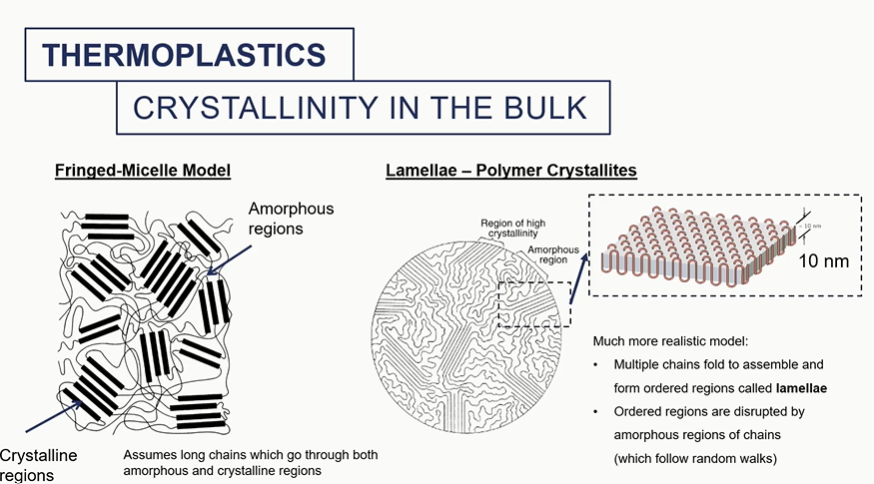
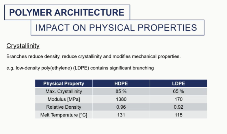
crystallinity in bulk
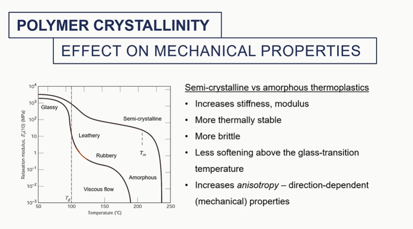
different amounts of crystallinity will impart different mechanical properties into these materials
It will change the melting temperature. It will change the density overall of the system and the modulus of that material
semi crystalline vs amorphous thermosplatics graph
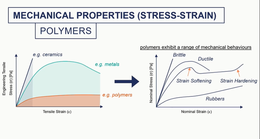
polymer graph
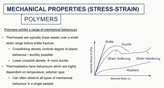
so ceramics, really brittle metals, some plasticity polymers, we can get much higher strength.
So thermostats being cross-linked networks. So we have chemical bonds between chains and thermoplastics we do not. so we have things that form like knots or sort of tangled string like structures um which give it give thermoplastics their mechanical properties.
So thermostats typically, a linear elastic over a small strain range And then they're going to fail by brittle fracture because we have these covalent bonds between chains. As soon as we exceed the energy required to break those bonds the material is going to fail.
If we reduce the cross-linking density of our thermosets
so we have fewer links between our polymer chains and our network, we've got a bit more scope for plastic deformation
So there's a bit more ductility, a bit more plastic behavior with lower degrees of cross-linking.

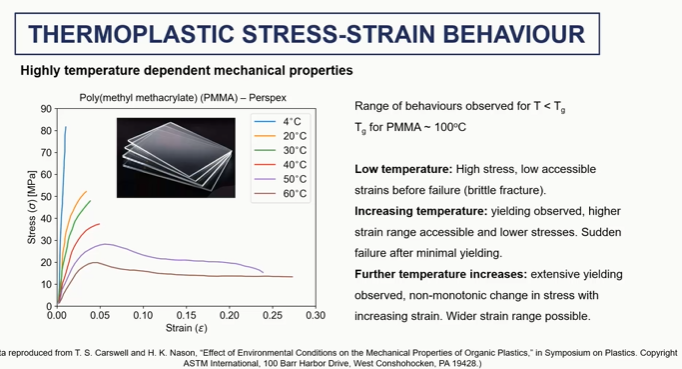
thermoplastics stress train behaviour graph
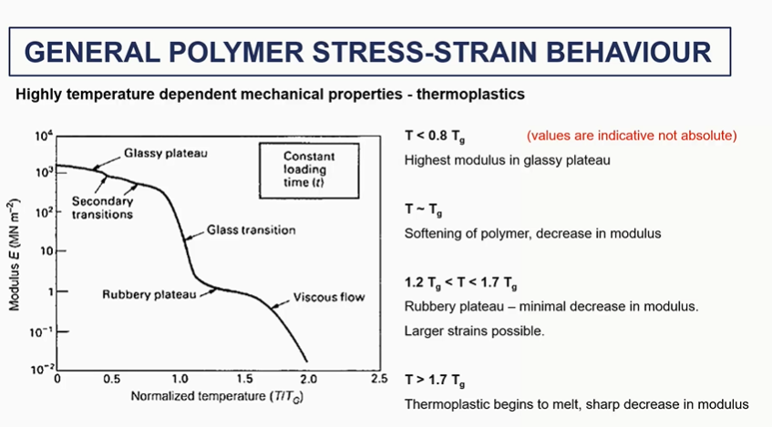
general polymer stress strain behaviour
regions of the polymer stress strain curve
very general
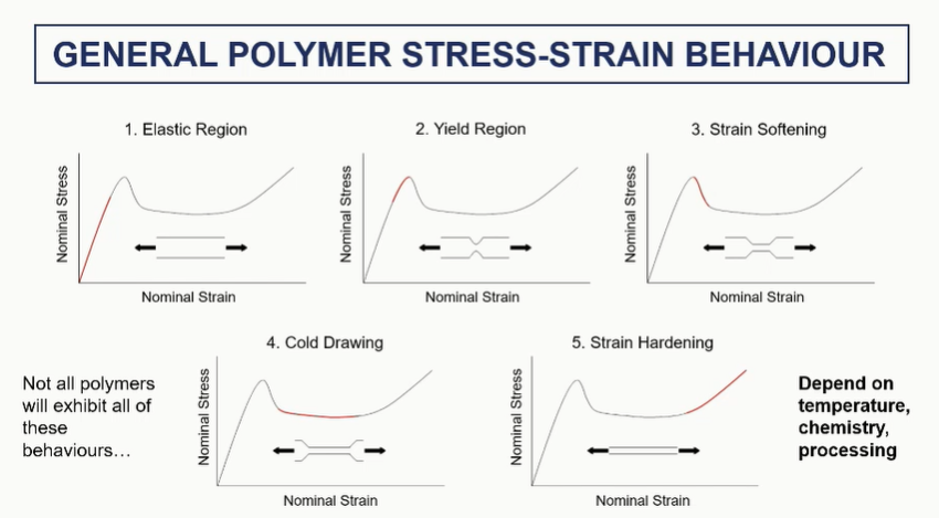
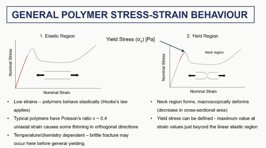
polymer stress strain elastic and yield regions (1 and 2)
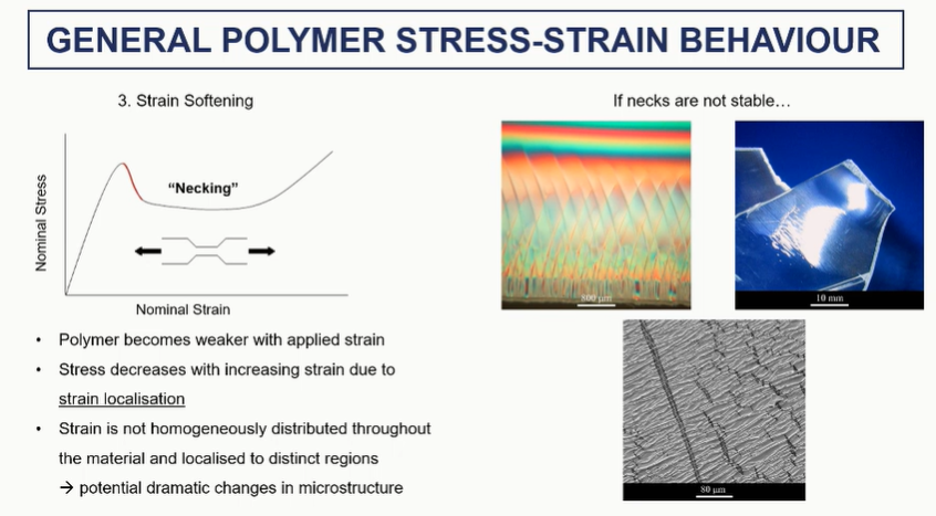
polymer stress strain strain sftening (3)
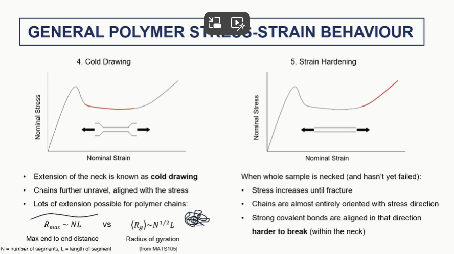
polymer stress strain cold drawing and steain harding regions (4 and 5)
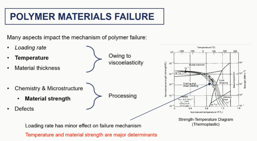
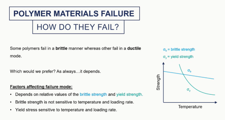
factors affecting failure
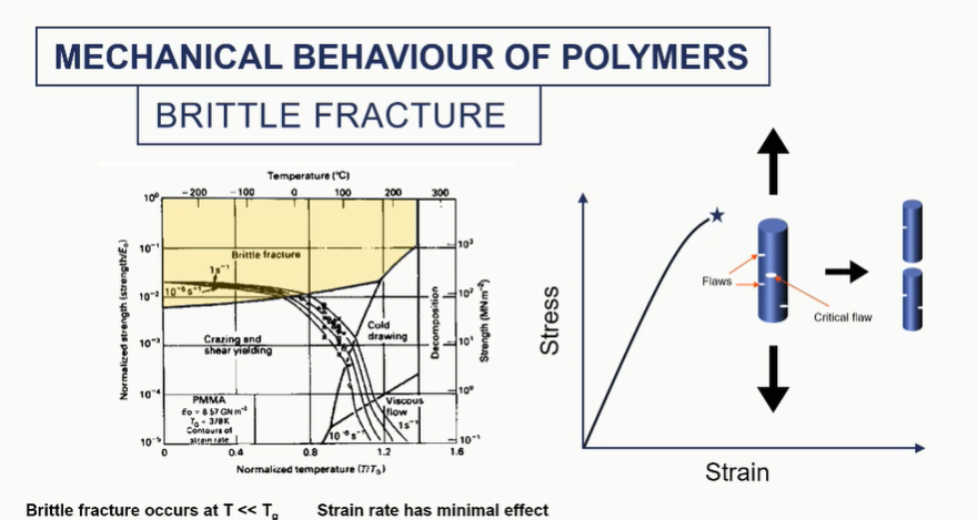
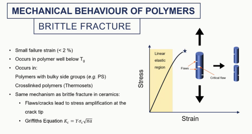
brittle fracture of polymers
brittel fracture micrstructure
We see a very clean sort of surface. so there's not any tearing or pulling here.
relatively clean fracture surface - with concentric circles
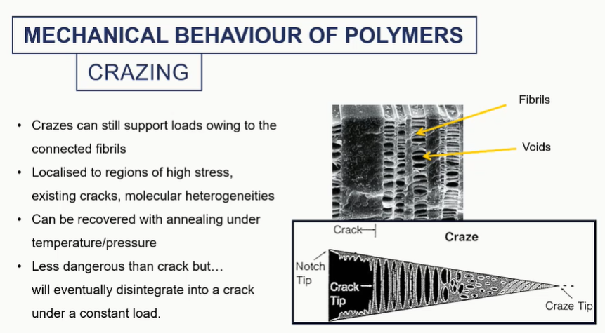
crazing graph
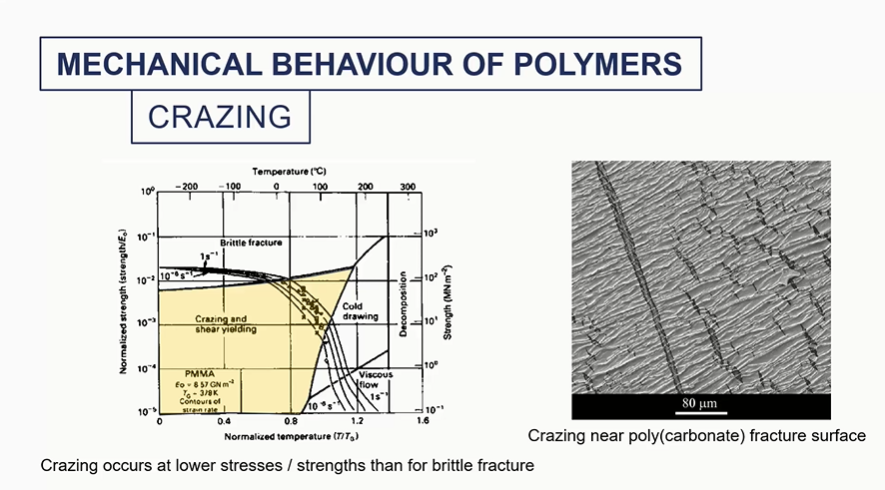
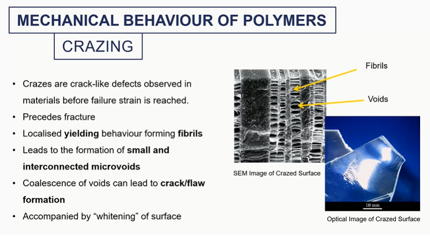
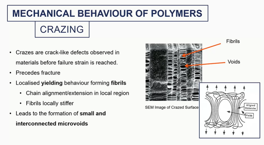
crazing mechanical behaviour
these voids will sort of coalesce, grow into a larger crack, which would then irreversibly fail by brittle fracture eventually.
we could actually save our material by annealing it. We could raise the temperature to basically soften these regions and make it sort of reform.
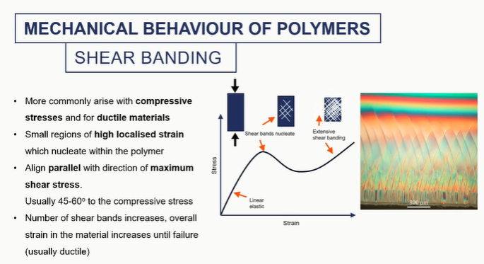
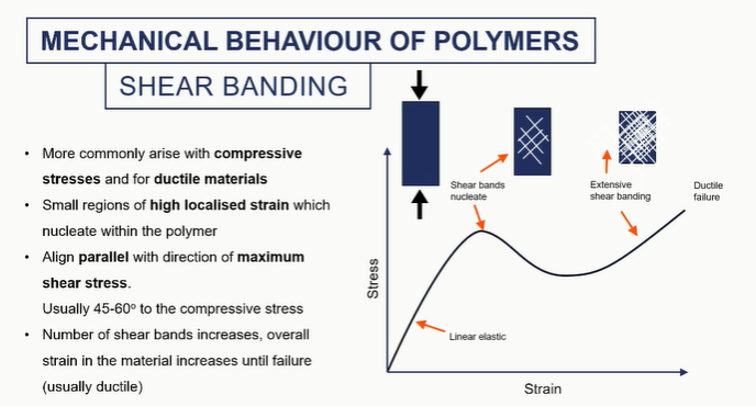
shar banding graph
shows that something is happenning to the microstructure
This is more common for ductile, uh, polymers. Things are not failing by brittle fracture or at much higher temperatures.
these shear bands are essentially really high regions of localised strain.
these are areas where the stress is not distributed equally and therefore the strain isn't, typically align 45 to 60 degrees, uh, with the compressive stress.
So they're going to align in a sort of odd angle. And they'll look like this sort of hatch pattern.
they will nucleate and grow sort of irreversibly until the material sort of fails.
like cracks, banding is a point of failure
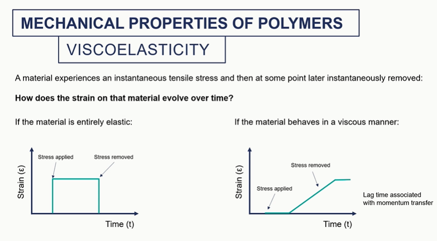
viscoelastc graphs
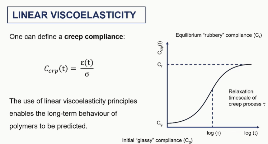
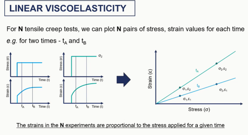
linear viscoelastic graphs / creep graph
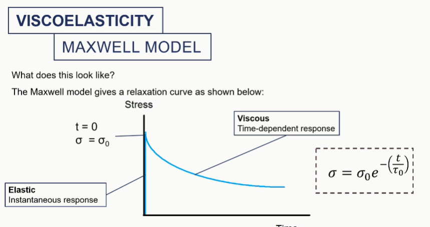
maxwell model graph