AC to DC - Rectifiers
1/29
Earn XP
Description and Tags
Name | Mastery | Learn | Test | Matching | Spaced |
|---|
No study sessions yet.
30 Terms
What is the main function of a rectifier?
To convert AC into DC.
Name three rectifier classifications.
Uncontrolled (diodes), Controlled (SCRs), Semi-controlled (diodes + SCRs).
What devices are used in uncontrolled rectifiers?
Diodes.
What devices are used in controlled rectifiers?
Thyristors (SCRs).
What devices are used in semi-controlled rectifiers?
Mix of SCRs and diodes.
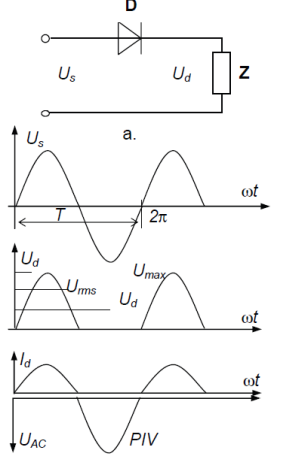
What is a single-phase half-wave rectifier?
One-diode circuit passing only positive half-cycles of AC.
What is a single-phase full-wave rectifier?
Circuit converting both halves of AC to pulsating DC using a center-tap or bridge.
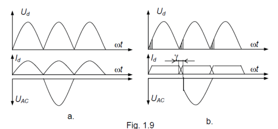
What is a three-phase full-wave rectifier?
Six-diode or six-SCR bridge providing smoother DC with less ripple.
What is the function of a freewheeling diode?
Maintain current in inductive loads when the main device turns off, reducing ripple. It protects rectifier components from reverse voltage that could damage diodes or SCRS. This all minimizes losses and torque ripple in DC motor drives
Define CCM.
Continuous Conduction Mode: inductor current never reaches zero.
Define DCM.
Discontinuous Conduction Mode: inductor current falls to zero each cycle.
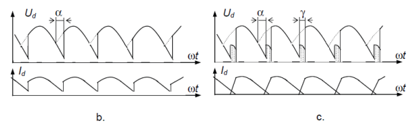
How is DC output of a controlled rectifier adjusted?
By changing SCR firing angle alpha.
Effect of increasing firing angle alpha?
Average DC output voltage decreases.
What happens if alpha > 90 degrees?
Average output can go negative (inversion region).
Common rectifier applications?
DC supplies, chargers, DC motor drives.
What is a dual rectifier?
A four-quadrant converter enabling bidirectional power flow (rectification and inversion).
Advantages of three-phase over single-phase?
Lower ripple, higher efficiency, better utilization.
How long is 1 degree at 60 Hz?
1/360 * 1/60 s which is approximately 46.3 us.
Describe half-wave rectifier output.
Positive half-sine pulses separated by zero; negative halves blocked.
Describe full-wave rectifier output.
Both halves become positive pulses, forming pulsating DC.
Describe RL load with freewheeling diode.
When main device turns off, current continues through diode, keeping current nearly continuous and load voltage positive.
r = \frac{V_{AC(rms)}}{V_{DC}} .
A lower ripple factor indicates smoother DC output.
Approximate ripple factors for single-phase rectifiers:
• Half-wave rectifier: 121 %
• Full-wave rectifier: 48.2 %.
Ripple is significantly reduced in full-wave rectifiers since current flows during both halves of the AC cycle.
Approximate ripple factors for three-phase rectifiers:
• 3-phase half-wave rectifier: 18.3 %
• 3-phase full-wave rectifier: 4.2 %.
Increasing the number of phases reduces ripple and improves DC smoothness.
Ripple can be reduced by:
• Using filters (capacitors, inductors, LC or RC filters).
• Increasing the number of phases.
• Adding smoothing capacitors across the load to store charge and fill voltage gaps.
Rectifier efficiency is the ratio of DC output power to total AC input power: \eta = \frac{P_{DC}}{P_{AC(input)}} \times 100\% .
It indicates how effectively AC power is converted into usable DC.
Approximate efficiencies for common rectifier types:
• Half-wave rectifier: ≈ 40 %
• Full-wave rectifier: ≈ 81 %.
Efficiency improves as both the conduction period and the number of pulses increase.
With an inductive load, current tends to remain continuous, lowering ripple.
Adding a freewheeling diode across an RL load also reduces ripple.
A larger capacitor reduces ripple by storing more charge. Ripple voltage (approximate): V_{r(pp)} = \frac{I_{load}}{f \, C} . Here f is the ripple frequency and C is the filter capacitance.