ECE 140 Post Midterm
 Call Kai
 Learn
Learn Practice Test
 Spaced Repetition
 Match
Match Flashcards
 Knowt Play
1/72

There's no tags or description
Looks like no tags are added yet.
Name | Mastery | Learn | Test | Matching | Spaced | Call with Kai | Chat |
|---|
No analytics yet
Send a link to your students to track their progress
73 Terms
Capacitor
Stores energy in Electric Field
Capacitance = Q/V
Energy in Capacitor = ½CV²
Resists changes to voltage
Inductor
Stores energy in Magnetic field
resists changes to current
Energy in an Inductor = 1/2LI²
L
Magnetic Inertia → inductance is the resistance to change in current
High Inductance → Very hard for the circuit to build up current (like pushing a heavy car) and when current does get flowing, very hard to stop it
Capacitor i = C * dV/dt
Q = CV
d(Q)/dt = d(CV)/dt
dQ/dt = CdV/dt (Capacitance is a constant)
i = C * dV/dt
This equation means current flowing in equals how fast the pile is growing
Can Voltage Jump?
No it cannot which implies infinite voltage and infinite current which is impossible
Inductor: v = Ldi/dt
Voltage across an inductor is caused by how fast the current is changing
Can current jump?
No it cannot, i(0-) = i(0+)
Inductors In Series
Leq = L1 + L2 + … + Ln
If you try to change the current of a inductor in series, both inductors will fight back
Inductors in Parallel
1/Leq = 1/L1 + 1/L2 + … + 1/Ln
Capacitors in Parallel
Ceq = C1 + C2 + Cn
Same as building a combined capacitor with bigger plates since the first plates of the parallel capacitors are connected to the same node and the bottom plate capacitors are connected to a respective same node
Capacitors in Series
1/Ceq = 1/C1 + 1/C2 + … + 1/Cn
Steady State Voltage
Circuit’s voltages and current reach constant values and the capacitor and inductors start acting like ideal components.
Initial Conditions
Capacitor → Vi is the initial condition
Inductor → Ii is the initial condition
Inductors Initial Conditions
If i have inductors in parallel, merge them together to form one big inductor and add their initial condition current together: i1(0) + i2(0) +…+ in(0)
Capacitors Initial Conditions
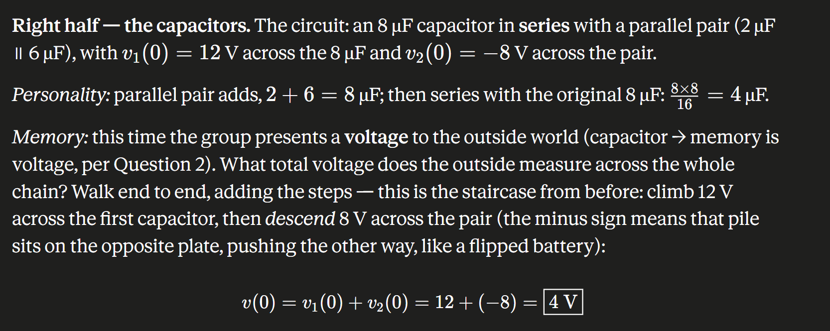
RC Step Response
V(t) = Vie-t/RC
Vi is the initial voltage before t = 0 (when switch is closed) → It is the initial voltage
RC Step Response basically measures how a resistor-capacitor circuit responds to a sudden change in voltage (How fast the capacitor soaks up charge or squeezes out charge)
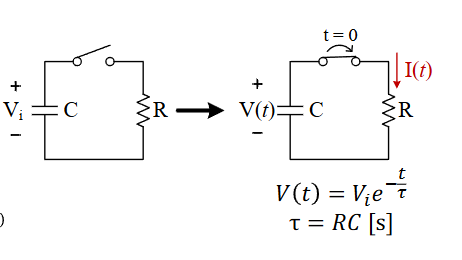
τ (tau)
τ = RC (Time constant) → Tells me how fast the circuit capacitor discharges
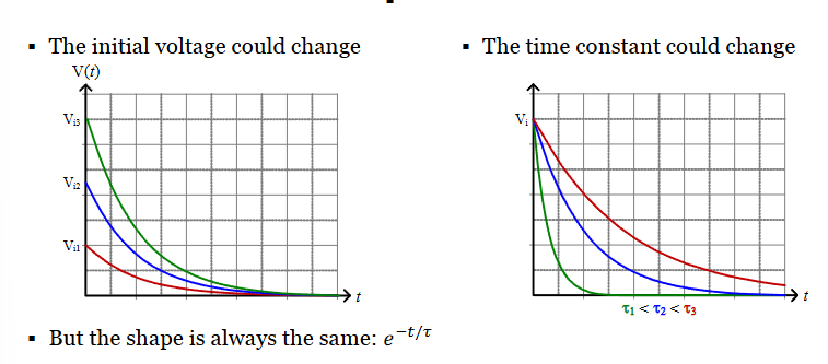
RC First-Order Response
Both graphs always result in exponential decay. Graph 1 shows that if tau is the same but different starting voltages, all three voltages will hit 0V at the same time.
Intuitively it makes sense, higher voltage at the start means higher pressure and more current, while lower voltage means less pressure, but less charge needed to pass through or whatever.
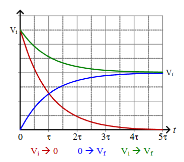
Charging and Discharging
You could start at Vi and charge up or discharge to Vf
In every case, the timing is set by RC and it follows the e-t/T curve
The Generalized RC Equation
V(t) = Vf + (Vi - Vf)e-t/tau
t < 0: Steady-State voltage, V(t) = Vi
t from 0 to 5tau → Goes from Vi to Vf following decaying exponential
t > 5tau → Steady-state V(t) = Vf
Inductor Charging and Discharging
I(t) = I1e-t/Tau tau = L/R
I(t) = If + (Ii - If)e-t/tau
What Happens to a Capacitor after a long time?
Acts like an open circuit as t→infinity, Ic = 0 (Steady State)
What happens to an inductor after a long time?
Acts like a plain wire/short circuit (Steady State)
Transient State
The period where capacitor, inductor, etc. takes to charge or discharge
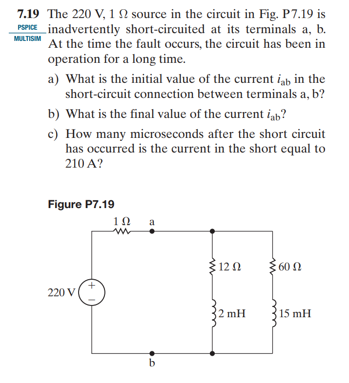
Short Circuit Example for Slideshow Algorithm
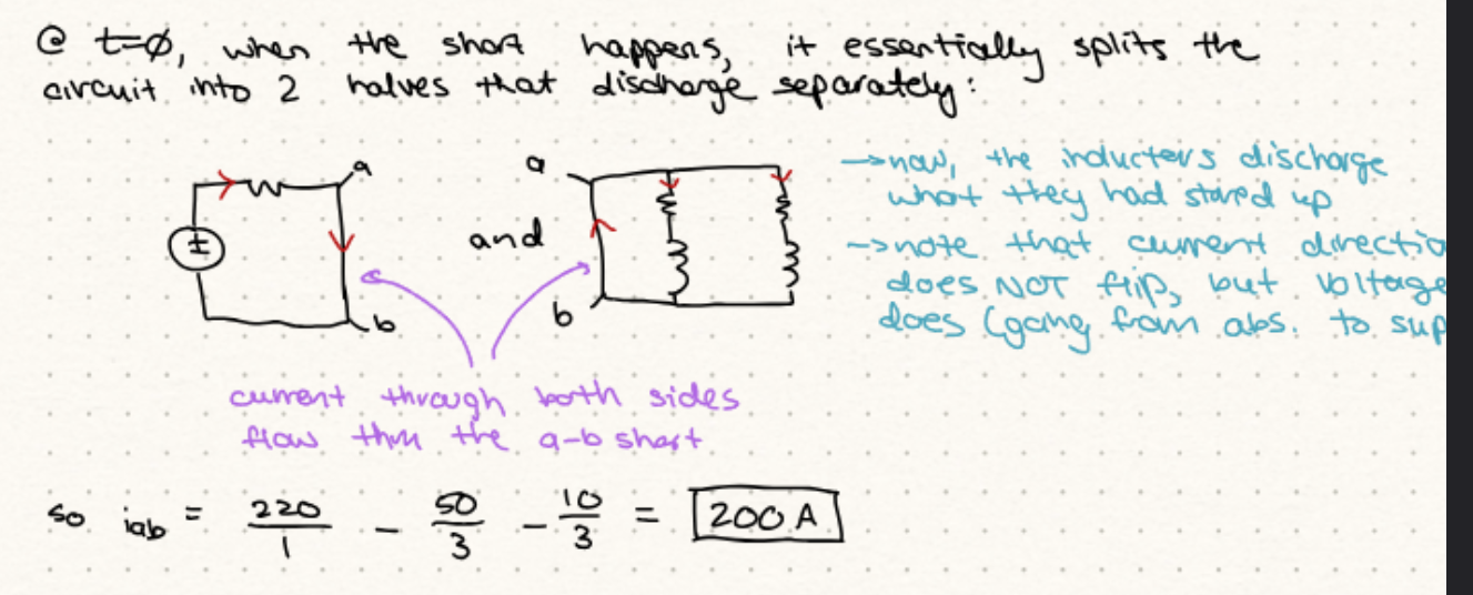
a) Find values of the current of isupply, the current going through each parallel branch with the inductors, then calculate Iab. The current through the inductors must complete the loop and will go through the short circuit, at the same time, the current from the source will be pushing down so the current through the short circuit is Iab = isupply - ibranch1 - ibranch2
b) After waiting a long time and having steady state, the current through the parallel branches will be 0 so isupply = iab
c) Split into two different inductor circuits for each branch. to complete the loop of each inductor circuit, the current flows through the short circuit branch so finding R for both to find tau is easy (Just the resistor value in each branch). Add them up and make them equal to 10A and solve for t from there after pluging in Tau (Should be cubic function)
Decoupling Method
Sinosoudal Steady State
Sinosoudal Voltage Source
Source that produces AC signal (varies sinusoidally wiht time)
Sinosoidal Current Source
Produces a current that varies sinusoidally with time
Sinosoudal Voltage
v = Vmcos(wt + phi)
Vm = max amplitude of the wave
RMS Voltage
DC Equivalent Voltage of AC Voltage
Vrms = Vm/sqrt(2)
Only depends on the max amplitude of the sinosoudal voltage

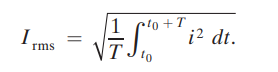
RMS Current
Steady State Response
Assume Initial Current = 0
Apply KVL to the circuit to get L(di/dt) + Ri = Vmcos(wt + phi)

4 Key Takeaways for sine/cosine wave
Always a sine/cosine wave (V = Ldi/dt → derivative of a smooth cosine wave is just a smooth sine wave)
Frequency of steady state solution matches the source exactly (w)
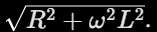
The amplitude of the current gets scaled down (There is resistance alongside inductive reactance which creates IMPEDENCE)
The steady state response phase angle is different from the phase angle of the source.
Impedence
The effects of resistance + Reactance
Phasor
A complex number that carries the amplitude and phase angle information of a sinusoidal function.
e+-jthetha = costhetha +- jsinthetha
Euler’s identity is essentially another way of representing cosine and sine functions
Time Domain
v(t) = Vmcos(wt + phi) → Tells us the actual voltage and what is happening at every millisecond
Phasor/Frequency Domain
V = Vm<θ. We only care about the phase angles and not the “wt” part (that is time domain) to simplify our calculations
Mutual Inductance
Imagine two inductor coils near each other (Like a transformer). When AC voltage goes through one inductor, it creates a magnetic field that spills over into the inductor which induces a voltage in it as well.
Therefore: Vcoil2 = jwMIcoil1 with M being mutual inductance
R{}
R{} is essentially just converting phasor voltage or phasor current into the real thing. It’s taking the projection of what would give the real voltage or real current
Inverse Phasor Transform
Takes the Phasor Voltage and converts it into real voltage

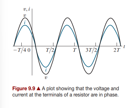
Relationship between Phasor Voltage and Phasor Current for a Resistor
V = RI (Phasor Voltage, includes imaginary and real components, used to make our calculations easier). Angles of Phasor voltage and current are in phase
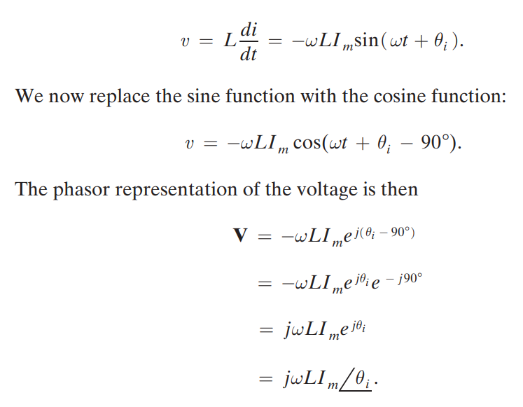
Inductor Phasor Voltage
V = jwLI
Multiplying by J is the exact same as rotating by 90 degrees, this means Phasor Voltage leaders Phasor current by 90 degrees.
ZL of Inductor
Impendence (ZL = jwL)
Phasor Current for Capacitor
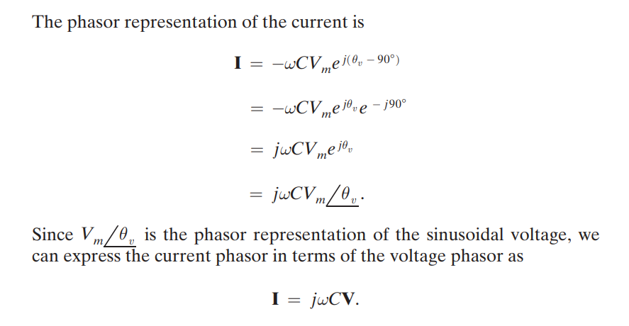
Relating Phasor Voltage and Phasor Current for Capacitor
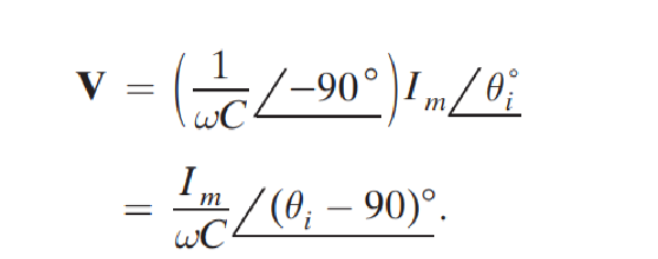
Relating Phasor Current and Phasor Voltage to Capacitor
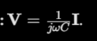
Definition of Impedance
V = ZI
Impedance Equation
Z = R + jX where X is reactance and the imaginary part and R is the real part.
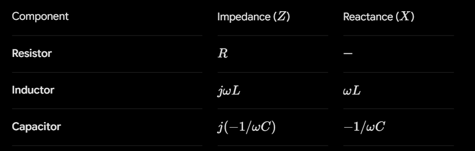
Impedance and Reactance Values
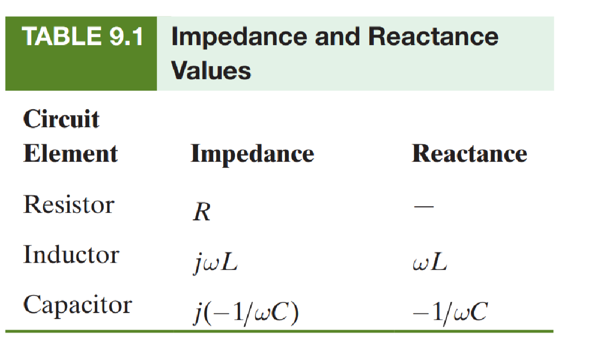
KVL in the Frequency Domain
KCL in Frequency Domain

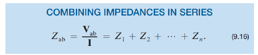
Combining Impedances in Series
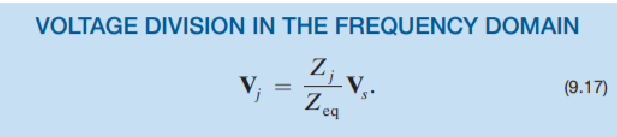
Voltage Division in Frequency Domain
Same process as doing normal voltage divisiona s before
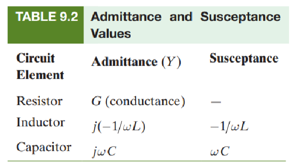
Admittance and Susceptance Table Values
Current Division in the Frequency Domain

Cramer’s Rule
Determinant rule best for 2 × 2 matrices and 3 × 3 matrices
If you have 2 voltage equations:
First make the two voltage equations and move constants to one side and keep Phasor voltage variables or current on one side
Put everything into a 2 × 2 matrix with V1’s elements covering top row and V2 elements covering bottom row
First determinant, you are calculating Δ. Put all the constants of each variable in the matrix and calculate the determinant to find Δ
Find ΔV1 by putting the constants that were put on one side in the earlier equations on the left side (V1 constant top left, V2 constant bottom left) and compute the determinant
Set V1 = ΔV1/V and compute V1
Do the same for V2 but this time put the constants on the right side to find ΔV2 and do V2 = ΔV2/Δ to get V2
Chapter 10
AC Power
Instantaneous Power p(t)
p(t) = v(t)i(t)
Real Power (P)
Average value of power wave. It represents the actual energy being consumed by the circuit to do real work (heating up a resistor, making a motor shaft turn, lighting a bulb, etc.)
Reactive Power (Q)
Wasted or bouncing power that is stored in the magnetic fields/electric fields of inductors and capacitors respectively that is sloshed back and forth and do no work. It is measured in VARs.
Power Factor
pf = cos(θv - θi)
Reactive Factor
rf = sin(θv - θi)
Converting Peak Voltage to RMS Voltage and Peak Current to RMS Current
Vm = Vpk = Vrms sqrt(2)
Im = Ipk = Irms sqrt(2)
DC. Steady State Analysis VS. AC Steady State Analysis
In DC Steady State, Capacitor acts like an open-circuit, inductor acts like a plain wire
in AC Steady State, nead to calculate their impedences
Complex Power (S) Definition

Complex Power Formula Using Purely Phasors

Complex Power Using Impedence & Current (Current is magnitude form, Impedence is phasor form)

Power Using Impedence and Voltage
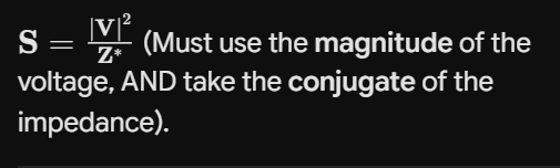
Real Power Component Only

Reactive Power Component Only