1750 Lower Extremity IA
 Call Kai
 Learn
Learn Practice Test
 Spaced Repetition
 Match
Match Flashcards
 Knowt Play
1/149

There's no tags or description
Looks like no tags are added yet.
Name | Mastery | Learn | Test | Matching | Spaced | Call with Kai | Chat |
|---|
No analytics yet
Send a link to your students to track their progress
150 Terms
AP or AP Axial Projections; Toes (CR & SS)
Perpendicular through the third MTP joint when it is not critical to demonstrate the joint spaces. To open the joint spaces, direct the central ray 15 degrees posteriorly through the third MTP joint or elevate the foot on a 15 degree foam wedge.
Images show the 14 phalanges of the toes; the distal portions of the metatarsals; and on the axial projections, the IP joints.
AP or AP Axial Projections; Toes (Eval Criteria)
• Evidence of proper collimation
• Entire toes, including distal ends of the metatarsals
• Toes separated from each other
• No rotation of phalanges; soft tissue width and midshaft concavity equal on both sides
• Open IP and MTP joint spaces on axial projections
• Soft tissues and bony trabecular detail
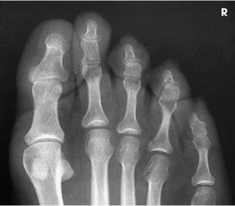
AP Projection; Toes
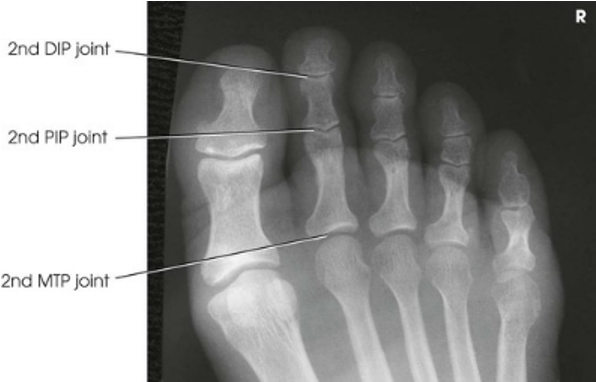
AP Axial Projection; Toes
AP Oblique Projection; Toes; Medial Rotation (CR & SS)
Perpendicular and entering the third MTP joint
An AP oblique projection of the phalanges shows the toes and the distal portion of the metatarsals rotated medially
(*Positioning: Medially rotate leg and foot to place plantar surface of foot at a 30-45 degree angle from IR)
AP Oblique Projection; Toes; Medial Rotation (Eval Criteria)
• Evidence of proper collimation
• Entire toes, including distal ends of the metatarsals
• Toes separated from each other
• Proper rotation of toes, as demonstrated by more soft tissue width and more midshaft concavity on elevated side
• Open IP and second through fifth MTP joint spaces
• First MTP joint (not always opened)
• Soft tissue and bony trabecular detail
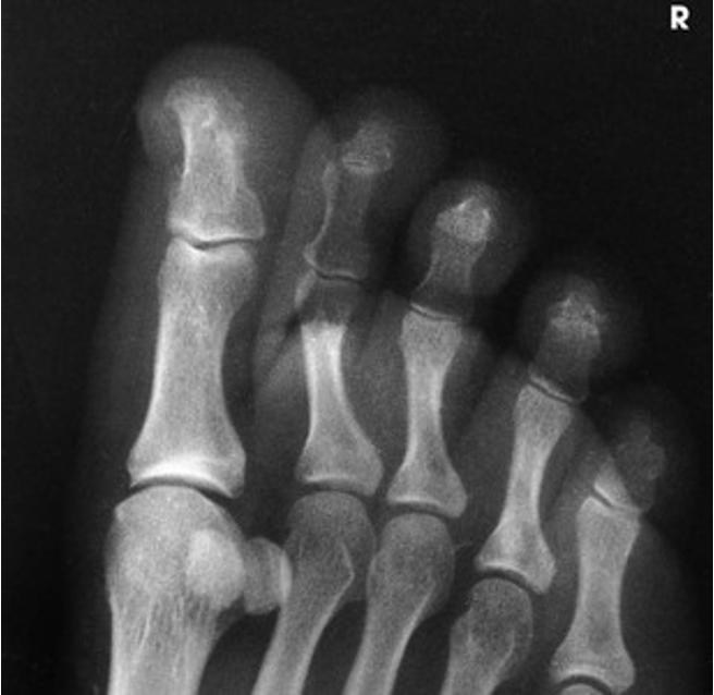
AP Oblique Projection; Toes; Medial Rotation
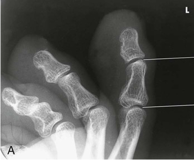
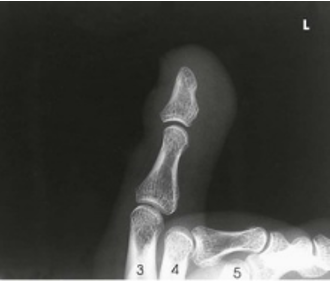
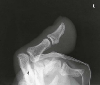
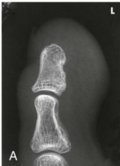
Lateral Projections; Toes; Mediolateral or lateromedial (CR & SS)
Perpendicular to the plane of the IR, entering the IP joint of the great toe or the proximal IP joint of the lesser toes
Images show a lateral projection of the phalanges of the toe and the IP articulations projected free of the other toes
Lateral Projections; Toes; Mediolateral or lateromedial (Eval Criteria)
• Evidence of proper collimation
• Entire toe, without superimposition of adjacent toes; when superimposition cannot be avoided, the proximal phalanx must be shown
• Toe(s) in a true lateral position
• Toenail in profile, if visualized and normal
• Concave, plantar surfaces of the phalanges
• No rotation of the phalanges
• Open IP joint spaces; the MTP joints are overlapped but may be seen in some patients
• Soft tissue and bony trabecular detail
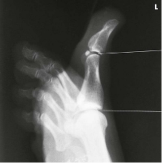
Lateral Great toe; lateromedial
Lateral second toe; lateromedial
Lateral Third Toe; Mediolateral
Lateral fourth toe; mediolateral
Lateral Fifth toe; mediolateral
Tangential Projection; Sesamoids; Lewis and Holly Methods (CR & SS)
Perpendicular and tangential to the first MTP joint
The resulting image shows a tangential projection of the metatarsal head in profile and the sesamoids
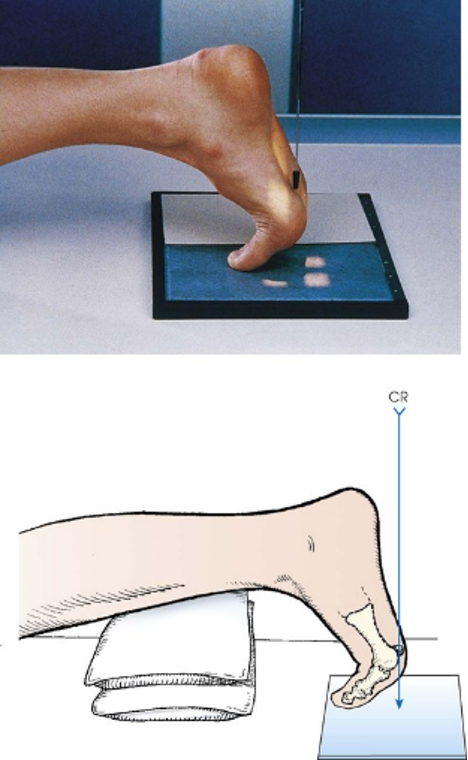
POSITIONING: Tangential Projection; Sesamoids; Lewis Method
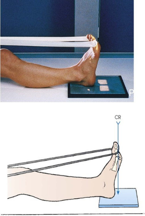
POSITIONGING: Tangential Projection; Sesamoids; Holly Method
Tangential Projection; Sesamoids; Lewis and Holly Methods (Eval Criteria)
• Evidence of proper collimation
• Sesamoids free of any portion of the first metatarsal
• Metatarsal heads
• Soft tissue and bony trabecular detail
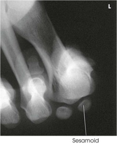
Tangential Projection; Sesamoids; Lewis Method
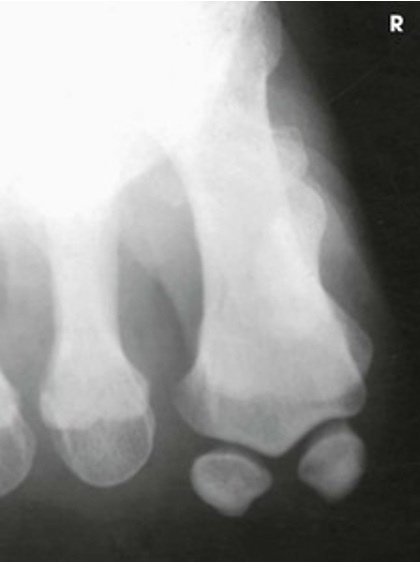
Tangential Projection; Sesamoids; Holly Method
AP or AP Axial Projection; Foot (CR & SS)
Directed one of two ways: (1) 10 degrees toward the heel entering the base of the third metatarsal or (2) Perpendicular to the IR and entering the base of the third metatarsal. (Palpating the prominent base of the fifth metatarsal assists in finding the third metatarsal.) The third metatarsal base is in the midline, approximately 1 inch anterior (Toward the toes)
The resulting image shows an AP (dorsoplantar) projection of the tarsals anterior to the talus, metatarsals, and phalanges. This projection is used for localizing foreign bodies, determining the locations of fragments in fractures of the metatarsals and anterior tarsals, and performing general surveys of the bones of the foot.
(*Using an angle will better visualize the tarsometatarsal joint spaces and will reduce foreshortening)
AP or AP Axial Projection; Foot (Eval Criteria)
• Evidence of proper collimation
• Anatomy from toes to tarsals; may include portions of talus and calcaneus
• No rotation of the foot, as demonstrated by equal amounts of space between the second through fourth metatarsals
• Overlap of the second through fifth metatarsal bases
• Axial projection resulting in improved demonstration of IP, MTP, and TMT joint spaces
• Open joint space between medial and intermediate cuneiforms
• Soft tissue and bony trabecular detail
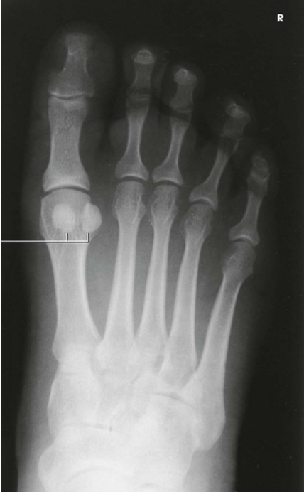
AP Projection; Foot
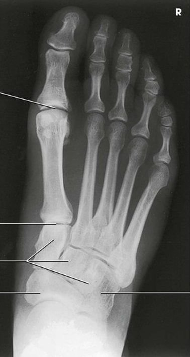
AP Axial Projection; Foot
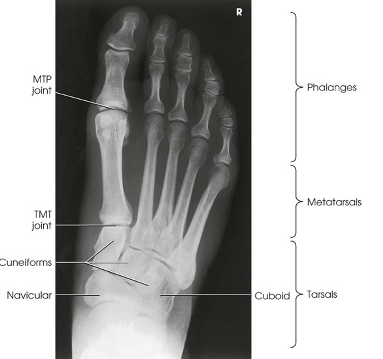
AP Axial Projection; Foot (Labeled)
AP Oblique Projection; Foot; Medial Rotation (CR & SS)
Perpendicular to the base of the third metatarsal
The resulting image shows the interspaces between the following: the cuboid and the calcaneus, the cuboid and the fourth and fifth metatarsals, the cuboid and the lateral cuneiform, and the talus and the navicular bone. The cuboid is shown in profile. The sinus tarsi is also well shown
(*Rotate the leg and foot 30 degrees medially. If more than 30 degrees is used, this will throw the lateral cuneiform over the other cuneiforms)
AP Oblique Projection; Foot; Medial Rotation (Eval Criteria)
• Evidence of proper collimation
• Entire foot, from toes to heel
• Proper rotation of foot
o Third through fifth metacarpals free of superimposition
o Bases of the first and second metatarsals superimposed on medial and intermediate cuneiforms
o Navicular, lateral cuneiform, and cuboid with less superimposition than in the AP projection
•Tuberosity of the fifth metatarsal
•Lateral TMT and intertarsal joints
•Sinus tarsi
•Soft tissue and bony trabecular detail
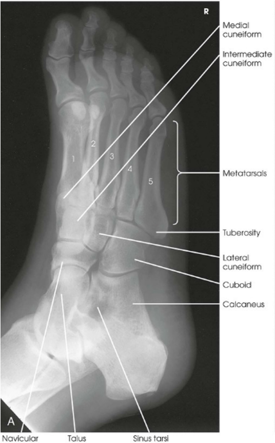
AP Oblique Projection; Foot; Medial Rotation
AP Oblique Projection; Foot; Lateral Rotation (CR & SS)
Perpendicular to the base of the third metatarsal
The resulting image shows the interspaces between the first and second metatarsals and between the medial and intermediate cuneiforms
(*Rotate the leg and foot 30 degrees laterally from the IR)
AP Oblique Projection; Foot; Lateral Rotation (Eval Criteria)
• Evidence of proper collimation
• Anatomy from toes to tarsals; may include portions of the talus and calcaneus.
• Proper rotation of foot
o 1st and 2nd metacarpal bases free of superimposition
o Minimal SI between medial and intermediate cuneiforms.
o Navicular seen with less foreshortening than on the medial rotation AP Oblique Projection.
• Soft tissue and bony trabecular detail
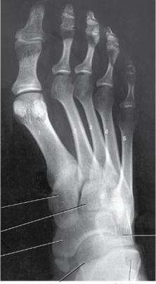
AP Oblique Projection; Foot; Lateral Rotation
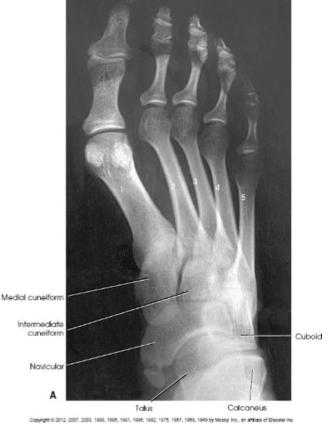
AP Oblique Projection; Foot; Lateral Rotation (Labeled)
Lateral Projection; Foot; Mediolateral (CR & SS)
Perpendicular to the base of the third metatarsal
The resulting image shows the entire foot in profile, the ankle joint, and teh distal ends of the tibia and fibula
(*2 different ways to position)
Lateral Projection; Foot; Mediolateral (Eval Criteria)
• Evidence of proper collimation
• Entire foot and distal leg
• Superimposed plantar surfaces of the metatarsal heads
• Fibula overlapping the posterior portion of the tibia
• Tibiotalar joint
• Soft tissue and bony trabecular detail
(*Domes of talus are superimposed)
If the knee is lifted on a lateral foot what happens to the domes of talus
Medial dome is inferior lateral dome is superior
If the heel is lifted on a lateral foot what happens to the domes of talus
Medial dome is anterior lateral dome is posterior
If the toes are lifted on a lateral foot what happens to the domes of talus
Medial dome is posterior lateral dome is anterior
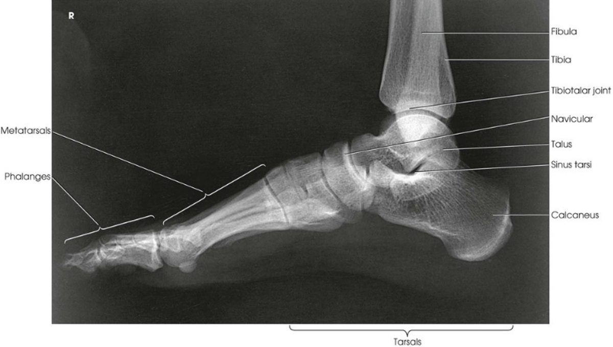
Lateral Projection; Foot; Mediolateral
Lateral Projection; Longitudinal Arch; Foot; Lateromedial; Weight-Bearing Method; Standing (CR & SS)
Perpendicular to a point just above the base of the third metatarsal
The resulting image shows a lateromedial projection of the bones of the foot with weight-bearing. The projection is used to shows the structural status of the longitudinal arch. The right and left sides are examined for comparison
Lateral Projection; Longitudinal Arch; Foot; Lateromedial; Weight-Bearing Method; Standing (Eval Criteria)
• Evidence of proper collimation
• Entire foot and distal leg
• Superimposed plantar surfaces of the metatarsal heads
• Fibula overlapping the posterior portion of the tibia
• Tibiotalar joint
• Soft tissue and bony trabecular detail
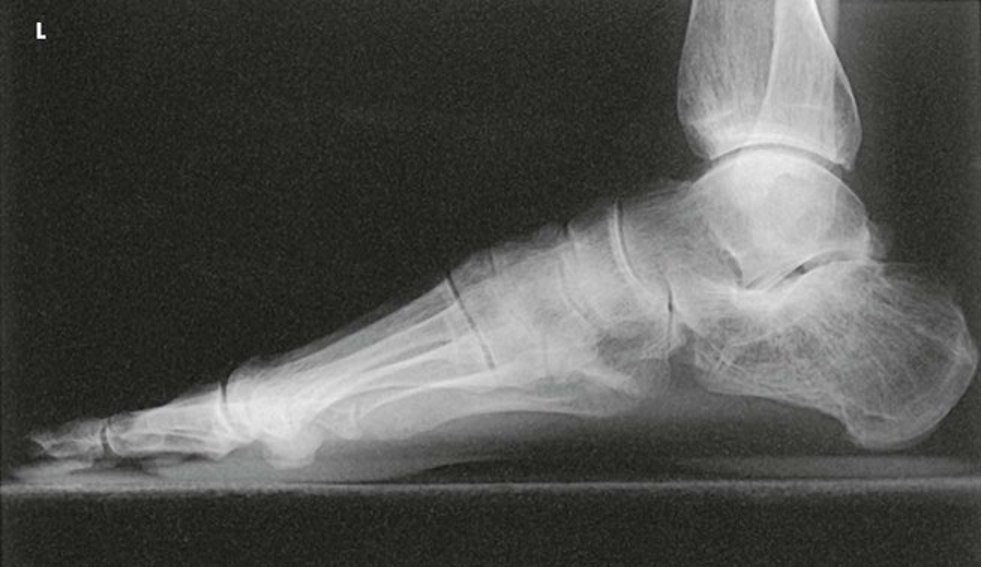
Lateral Projection; Longitudinal Arch; Foot; Lateromedial; Weight-Bearing Method; Standing
AP Axial Projection; Feet; Weight-Bearing Method; Standing (CR & SS)
Angled 10 degrees toward the heel is optimal. (A minimum of 15 degrees is usually necessary to have enough room to position the tube and allow the patient to stand.) The central ray is positioned between the feet and at the level of the base of the third metatarsal
The resulting image shows a weight-bearing AP axial projection of both feet, permitting accurate evaluation and comparison of the tarsals and metatarsals
AP Axial Projection; Feet; Weight-Bearing Method; Standing (Eval Criteria)
• Evidence of proper collimation
• Both feet centered on one image
• Anatomy from toes to tarsals; may include portions of talus and calcaneus
• Correct right and left marker placement and a weight-bearing marker
• Soft tissue and bony trabecular detail
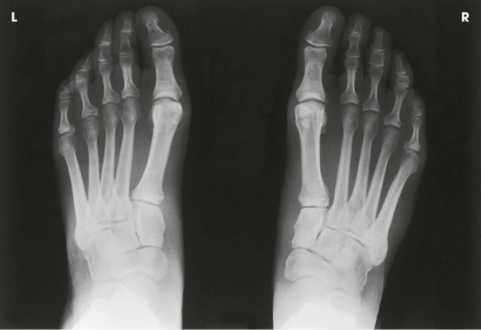
AP Axial Projection; Feet; Weight-Bearing Method; Standing
Axial Projection; Calcaneus; Plantodorsal (CR & SS)
Directed to the midpoint of the IR at a cephalic angle (entering the plantar surface and toward the heel) of 40 degrees to the long axis of the foot. The central ray enters near the base of the third metatarsal
The resulting image shows an axial projection of the calcaneus
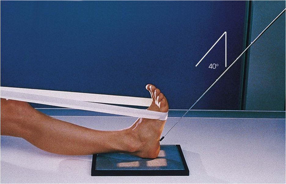
Positioning: Axial Projection; Calcaneus; Plantodorsal
Axial Projection; Calcaneus; Plantodorsal (Eval Criteria)
• Evidence of proper collimation
• Calcaneus and subtalar joint
• No rotation of the calcaneus—the first or fifth metatarsals not projected to the sides of the foot
• Anterior portion of the calcaneus with brightness similar to the posterior portion; otherwise, two images may be needed for the two regions of thickness
• Soft tissue and bony trabecular detail
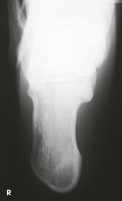
Axial Projection; Calcaneus; Plantodorsal
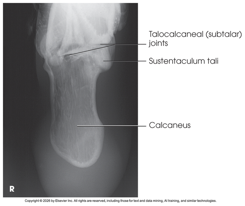
Axial Projection; Calcaneus; Plantodorsal Labeled
Axial Projection; Calcaneus; Dorsoplantar (CR & SS)
Directed to the midpoint of the IR at a 40 degree caudal angle to the long axis of the foot (enters posterior surface and toward the heel). The central ray enters the dorsal surface of the ankle joint
An axial projection of the calcaneus and the talocalcaneal (subtalar) joints. CT is often used to show this anatomy
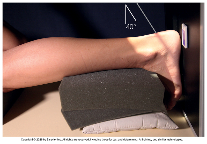
Positioning: Axial Projection; Calcaneus; Dorsoplantar
Axial Projection; Calcaneus; Dorsoplantar (Eval Criteria)
The side marker placed clear of the anatomy of interest
Calcaneus and the talocancaneal (Subtalar) joints
No rotation of the calcaneus
Sustentaculum tali in profile on the medial side
The first or fifth metatarsals not visible on either side
Bony trabecular detail and surrounding soft tissues
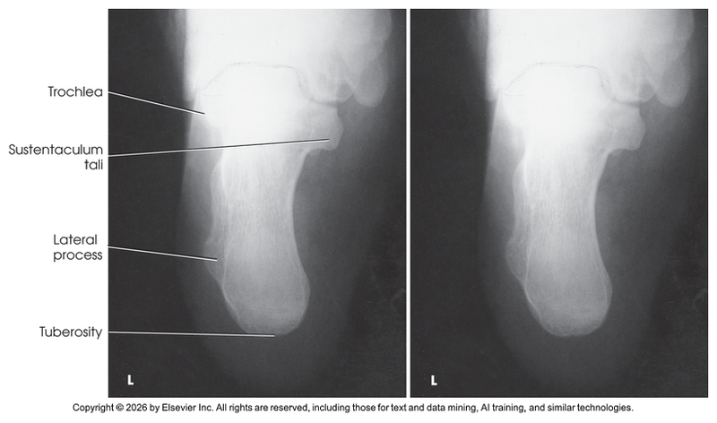
Axial Projection; Calcaneus; Dorsoplantar
Lateral Projection; Calcaneus; Mediolateral (CR & SS)
Perpendicular to the calcaneus. Center about 1 inch (2.5 cm) distal to the medial malleolus. This places the central ray at the subtalar joint.
The radiograph shows the ankle joint and the calcaneus in lateral profile
Lateral Projection; Calcaneus; Mediolateral (Eval Criteria)
• Evidence of proper collimation
• Entire calcaneus, including ankle joint and adjacent tarsals
• No rotation of the calcaneus
o Tuberosity in profile
o Sinus tarsi open
o Calcaneocuboid and talonavicular joints open
• Soft tissue and bony trabecular detail
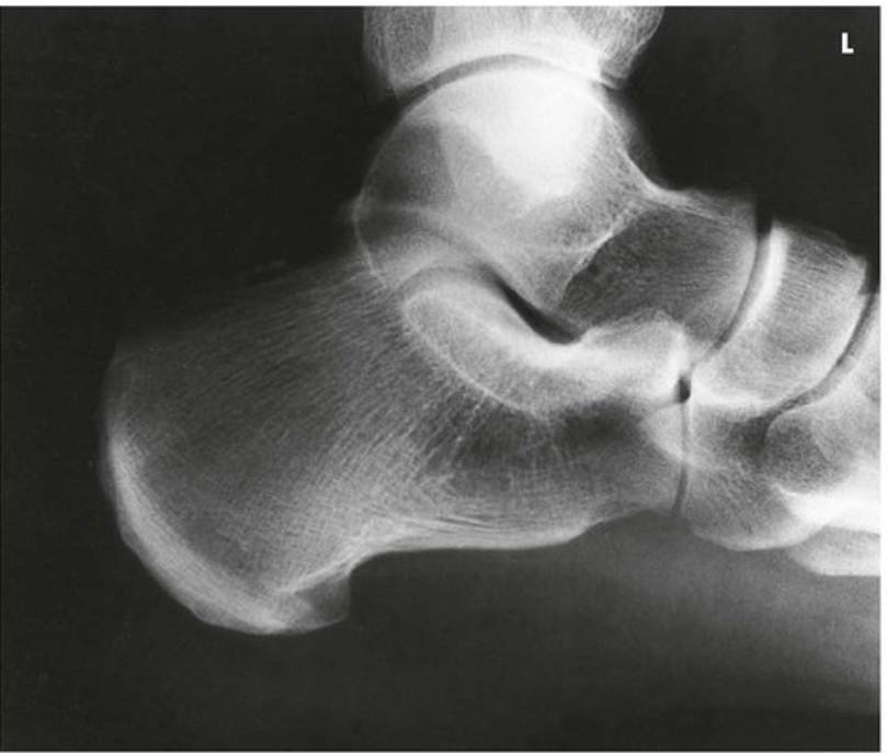
Lateral Projection; Calcaneus; Mediolateral
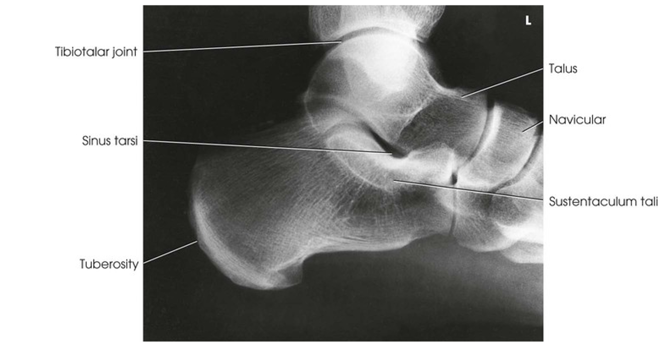
Lateral Projection; Calcaneus; Mediolateral (Labeled)
AP Projection; Ankle (CR & SS)
Perpendicular through the ankle joint at a point midway between the malleoli
The image shows a true AP projection of the ankle joint, the distal ends of the tibia and fibula, and the proximal portion of the talus.
NOTE: The inferior tibiofibular articulation and the talofibular articulation are not “open” or shown in profile in the true AP projection. This is a positive sign for the radiologist because it indicates that the patient has no ruptured ligaments or other types of separations. For this reason, it is important that the position of the ankle be anatomically “true” for the AP projection shown.
AP Projection; Ankle (Eval Criteria)
• Evidence of proper collimation
• Ankle joint centered to exposure area
• Medial and lateral malleoli
• Talus with proper brightness
• No rotation of the ankle
o Normal overlapping of the tibiofibular articulation with the anterior tubercle slightly superimposed over the fibula
o Talus slightly overlapping the distal fibula
o No overlapping of the medial talomalleolar articulation
• Tibiotalar joint space
• Soft tissue and bony trabecular detail
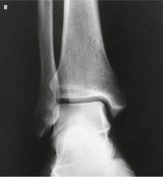
AP Projection; Ankle
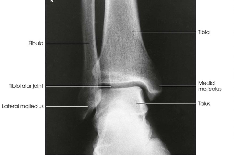
AP Projection; Ankle (Labeled)
AP Projection; Ankle; Stress Method
• AP ankle in neutral position. Use of lead glove and stress of the joint are required to obtain inversion and eversion radiographs.
• Stress studies usually taken after an inversion/eversion injury to verify presence of a ligamentous tear
• Demonstrated by widening of joint space
• Foot is forcibly turned toward opposite side of injury
• Physician adjusts foot to stress position and either he will hold it or patient will hold with strap
• Usually done after anesthetic has been given to patient
• Anesthetic is sometimes injected into the sinus tarsi
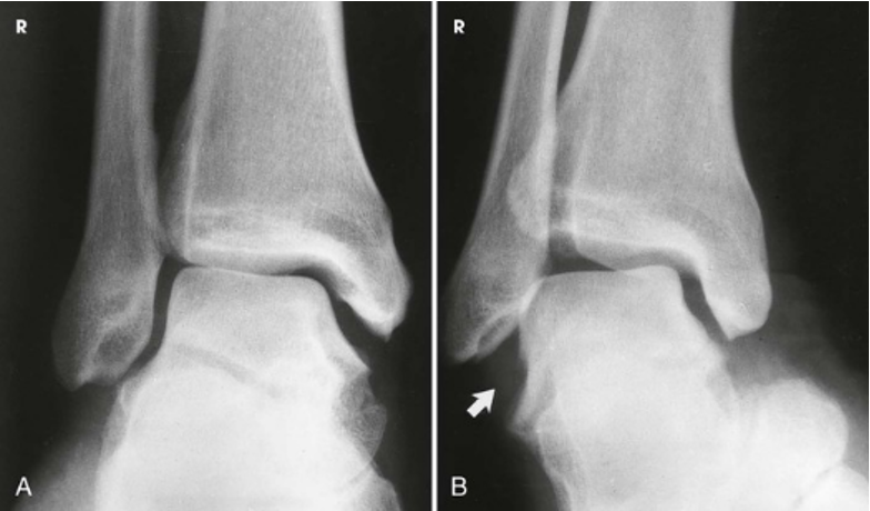
AP Projection; Ankle; Stress Method; A)Eversion stress. No damage to medial ligament is indicated. B) Inversion stress. Change in joint and rupture of lateral ligament (arrow) are seen.
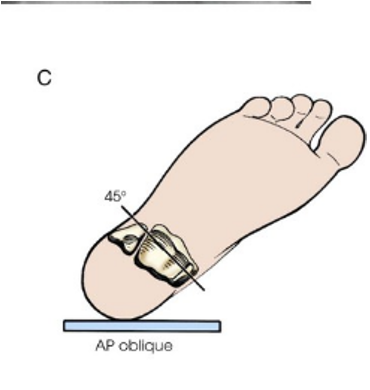
AP Oblique Projection; Ankle; Medial Rotation (CR & SS)
Perpendicular to the ankle joint, entering the medial malleolus
The 45 degree medial oblique projection shows the distal ends of the tibia and fibula, parts of which are often superimposed over the talus. The tibiofibular articulation also should be shown
AP Oblique Projection; Ankle; Medial Rotation (Eval Criteria)
• Evidence of proper collimation
• Ankle joint centered to exposure area
• Distal tibia, fibula, and talus
• Proper 45-degree rotation of ankle
• Tibiofibular articulation open
• Distal tibia and fibula overlap some of the talus
• Soft tissue and bony trabecular detail
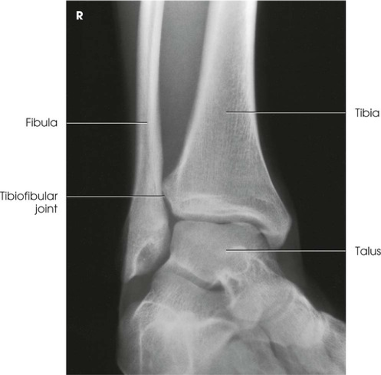
AP Oblique Projection; Ankle; Medial Rotation
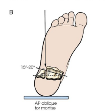
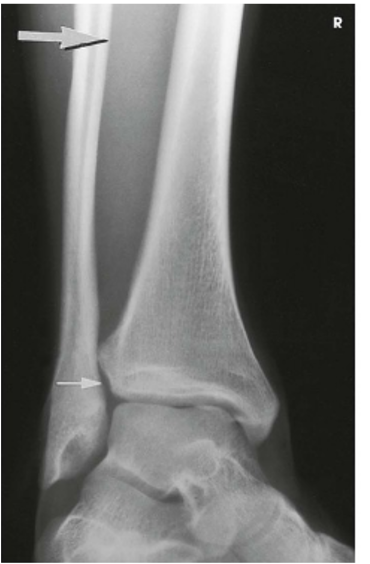
AP Oblique Projection; Ankle; Mortise Joint; Medial Rotation (CR & SS)
Perpendicular to the ankle joint, entering the medial malleolus
The entire ankle mortise joint should be shown in profile. The three sides of the mortise joint should be visualized
(*Rotate the entire leg 15-20 degrees until the intermalleolar plane is parallel with the IR)
AP Oblique Projection; Ankle; Mortise Joint; Medial Rotation (Eval Criteria)
• Evidence of proper collimation
• Entire ankle mortise joint centered to exposure area
• Distal tibia, fibula, and talus
• Proper 15- to 20-degree rotation of ankle
o Talofibular articulation open
o Tibiotalar articulation open
o No overlap of the anterior tubercle of the tibia and the superolateral portion of the talus with the fibula
• Soft tissue and bony trabecular detail
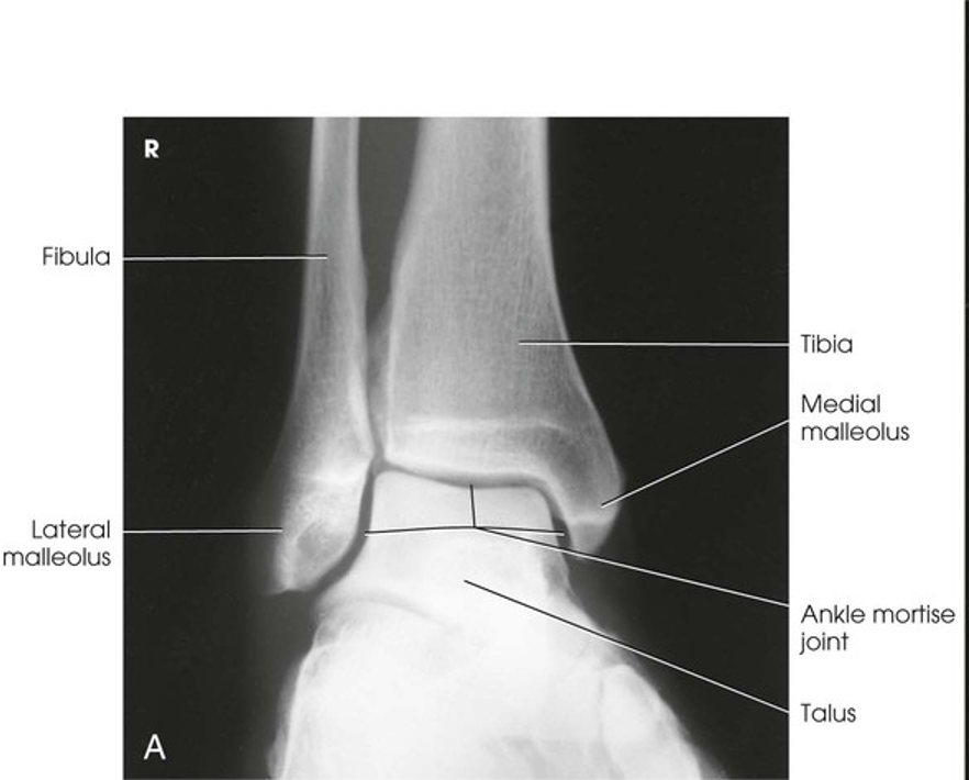
AP Oblique Projection; Ankle; Mortise Joint; Medial Rotation
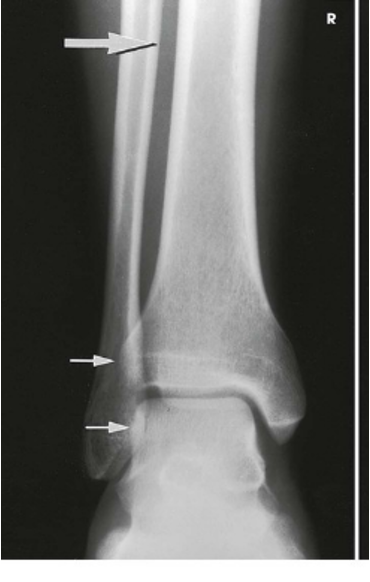
AP Projection; Ankle
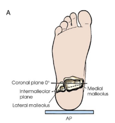
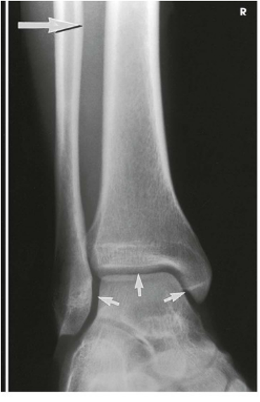
AP Oblique for mortise
AP Oblique
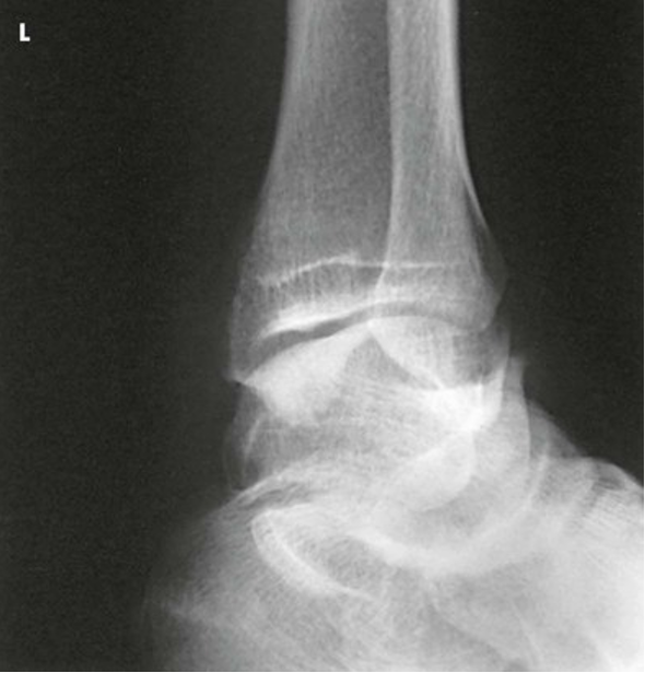
AP Oblique Projection; Ankle; Lateral Rotation (CR & SS)
Perpendicular to the ankle joint, entering the medial malleolus
The lateral rotation oblique projection is useful in determining fractures and showing the superior aspect of the calcaneus
(*Rotate the leg and foot 45 degrees externally)
AP Oblique Projection; Ankle; Lateral Rotation (Eval Criteria)
• Evidence of proper collimation
• Distal tibia, fibula, and talus
• Tibiotalar joint
• Calcaneal sulcus (superior portion of calcaneus)
• Soft tissue and bony trabecular detail
AP Oblique Projection; Ankle; Lateral Rotation
Lateral Projection; Ankle; Mediolateral (CR & SS)
Perpendicular to the ankle joint entering the medial malleolus
The resulting image shows a true lateral projection of the lower third of the tibia and fibula; the ankle joingt; and the tarsals, including the base of the fifth metatarsal
Lateral Projection; Ankle; Mediolateral (Eval Criteria)
• Evidence of proper collimation
• Ankle joint centered to exposure area
• Distal tibia and fibula, talus, calcaneus, and adjacent tarsals
• Ankle in true lateral position
o Tibiotalar joint well visualized, with the medial and lateral talar domes superimposed
o Fibula over the posterior half of the tibia
• Fifth metatarsal base and tuberosity should be seen to check for Jones fracture
• Brightness and contrast of the ankle sufficient to see the outline of distal portion of the fibula
• Soft tissue and bony trabecular detail
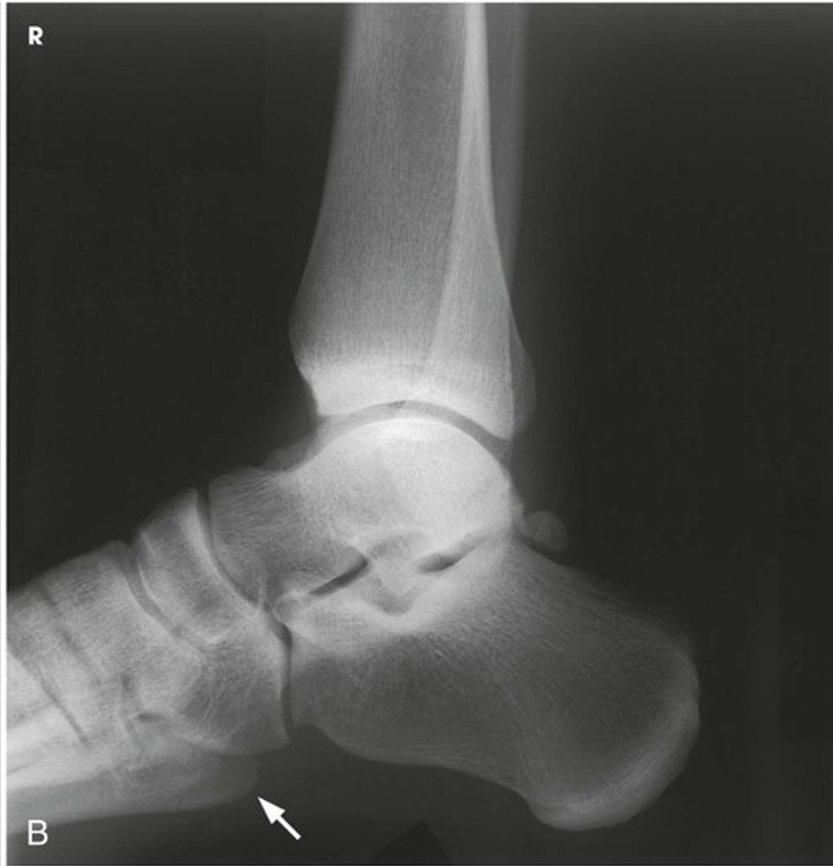
Lateral Projection; Ankle; Mediolateral
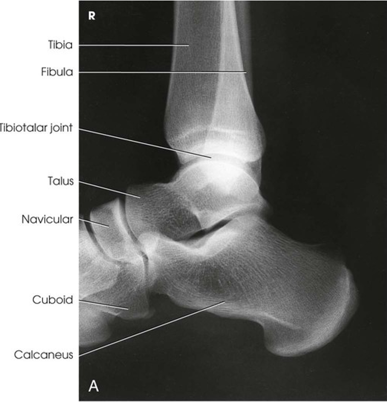
Lateral Projection; Ankle; Mediolateral (labeled)
AP Projection; Leg (CR & SS)
Perpendicular to the center of the leg
The resulting image shows the tibia, fibula, and adjacent joints
(Sometimes done on two separate films. Can fit almost ALL tib/fibs on 1 if you turn the cassette or collimator box diagonal. You can increase the SID in addition to placing the cassette diagonal to ensure both joints are included)
AP Projection; Leg (Eval Criteria)
• Evidence of proper collimation
• Ankle and knee joints on one or more images
• Entire leg without rotation
• Proximal and distal articulations of the tibia and fibula moderately overlapped
• Fibular midshaft free of tibial superimposition
• Soft tissue and bony trabecular detail
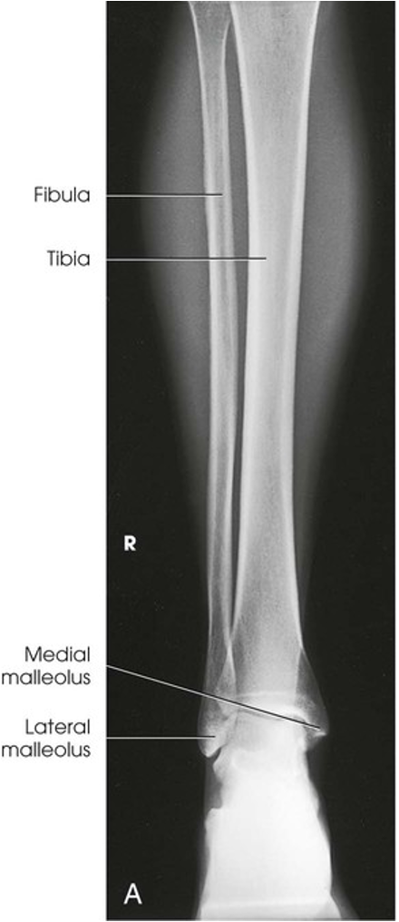
AP Projection; Leg (Labeled)
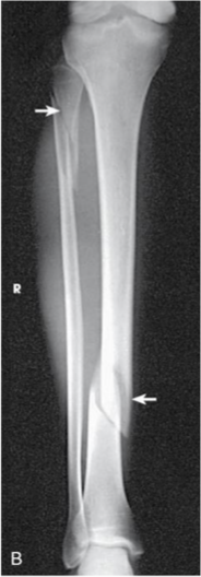
AP Projection; Leg
Lateral Projection; Leg; Mediolateral (CR & SS)
Perpendicular to the midpoint of the leg
The resulting image shows the tibia, fibula, and adjacent joints
Lateral Projection; Leg; Mediolateral (Eval Criteria)
• Evidence of proper collimation
• Ankle and knee joints on one or more images
• Entire leg in true lateral position
o Distal fibula lying over the posterior half of the tibia
o Slight overlap of the tibia on the proximal fibular head
o Moderate separation of the tibial and fibular bodies or shafts (except at their articular ends)
• Possibly no superimposition of femoral condyles because of divergence of the beam
• Soft tissue and bony trabecular detail
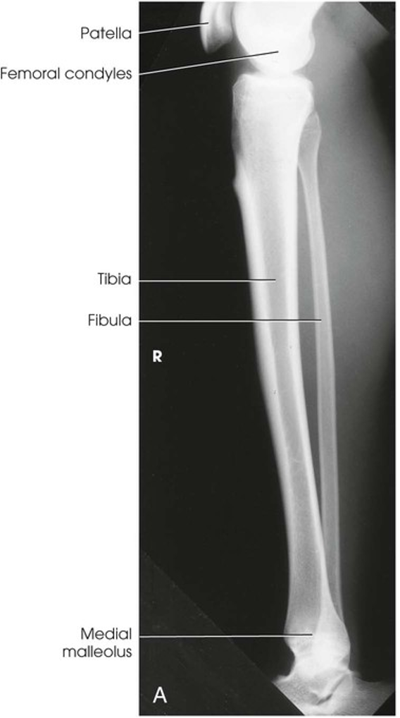
Lateral Projection; Leg; Mediolateral
AP Projection; Knee (CR & SS)
Directed to a point ½ inch (1.3 cm) inferior to the patellar apex
Variable, depending of the measurement between the anterior superior iliac spine (ASIS) and the tabletop
The resulting image shows an AP projection of the knee structures
ASIS to tabletop measurement <19cm
Angle tube 3-5 degrees caudad
ASIS to tabletop measurement 19-24cm
Angle tube 0 degrees
ASIS to tabletop measurement >24cm
Angle tube 3-5 degrees cephalad
AP Projection; Knee (Eval Criteria)
• Evidence of proper collimation
• Knee fully extended if patient's condition permits
• Entire knee without rotation
o Femoral condyles symmetric and tibia intercondylar eminence centered
o Slight superimposition of the fibular head if the tibia is normal
o Patella completely superimposed on the femur
• Open femorotibial joint space, with interspaces of equal width on both sides if the knee is normal (this is why we angle tube)
• Soft tissue and bony trabecular detail
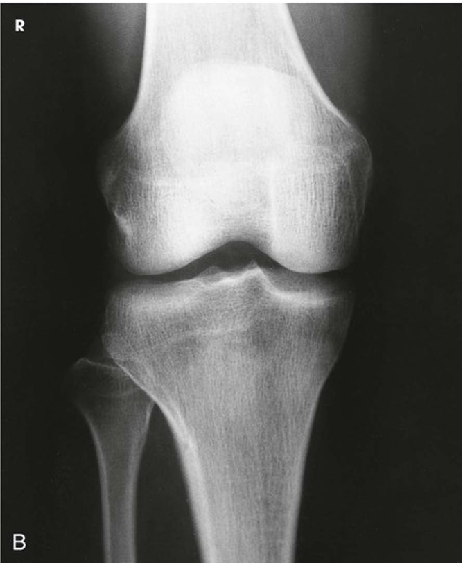
AP Projection; Knee
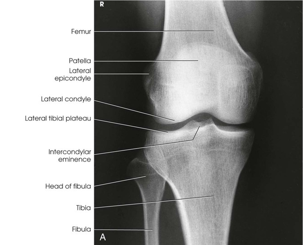
AP Projection; Knee (Labeled)
AP Oblique Projection; Knee; Lateral Rotation (CR & SS)
Directed image ½ inch (1.3 cm) inferior to the patellar apex. The angle is variable, depending on measurement between ASIS and the tabletop (Same chart as for AP)
The resulting image shows and AP oblique projection of the laterally rotated femoral condyles, patella, tibial condyles, and head of the fibula
AP Oblique Projection; Knee; Lateral Rotation (Eval Criteria)
• Evidence of proper collimation
• Medial femoral and tibial condyles
• Tibial plateaus
• Fibula superimposed over the lateral half of the tibia
• Margin of the patella projected slightly beyond the edge of the lateral femoral condyle
• Open knee joint
• Soft tissue and bony trabecular detail
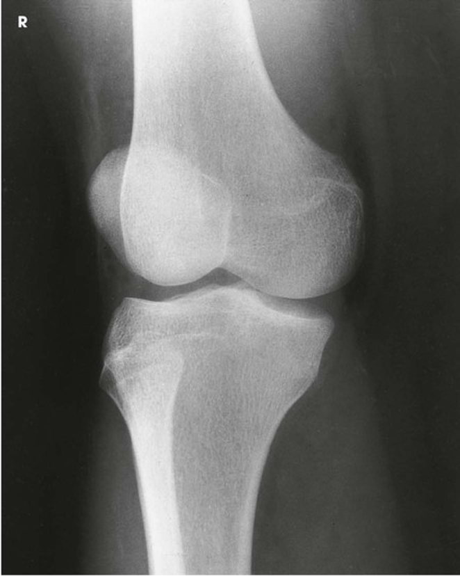
AP Oblique Projection; Knee; Lateral Rotation
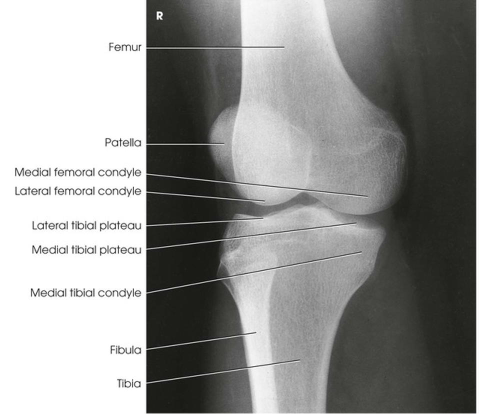
AP Oblique Projection; Knee; Lateral Rotation (Labeled)
AP Oblique Projection; Knee; Medial Rotation (CR & SS)
Directed image ½ inch (1.3 cm) inferior to the patellar apex. The angle is variable, depending on measurement between the ASIS and the tabletop (Same chart as AP)
The resulting image shows and AP oblique projection of the medially rotated femoral condyles, patella, tibial condyles, and the head of the fibula
AP Oblique Projection; Knee; Medial Rotation (Eval Criteria)
• Evidence of proper collimation
• Tibia and fibula separated at their proximal articulation
• Posterior tibia
• Lateral condyles of the femur and tibia
• Both tibial plateaus
• Margin of the patella projecting slightly beyond the medial side of the femoral condyle
• Open knee joint
• Soft tissue and bony trabecular detail
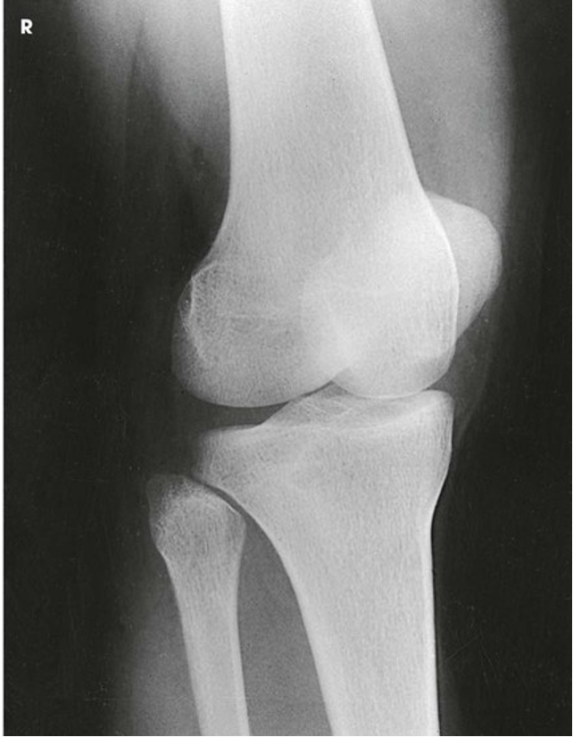
AP Oblique Projection; Knee; Medial Rotation