Technology
1/26
Earn XP
Name | Mastery | Learn | Test | Matching | Spaced |
|---|
No study sessions yet.
27 Terms
Design and communication
The design process
(geck this website for the vidio https://www.bbc.co.uk/bitesize/topics/ztcrjfr/articles/ztwcjfr#zpq97v4)
We all love coming up with ideas and solutions to problems, but if we do not carefully consider our approach to the development of the solution, what we manufacture may not meet the client’s needs.
The design process provides us with a series of important stages during the design and development of a solution.
Note:
The order of these stages is not fixed and will change depending on the design opportunity.
The process is often considered as a design cycle. The designer evaluates and improves their design ideas repeatedly until a solution is developed.
03:00
Video Transcript
Stages of the design process
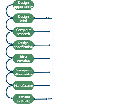
Image caption,
The design process is often considered as a design cycle. Ideas are evaluated and researched repeatedly at each stage of the process
Design opportunity
Design opportunities arise out of real-life situations. These can be a problem that already exists or a new idea to deal with a situation.
The designers will set out to solve a problem or create a solution that meets the needs identified in the design opportunity.
Design brief
This is a short statement that outlines the problem to be solved. The designer will use information in the design brief to carry out further research and develop possible solutions.
Research
Research will involve looking closely at the design opportunity to clarify exactly what the client needs.
Research will also help gain new knowledge into areas that will help design the solution.
Areas of research may include
analysis of similar solutions
investigation of suitable materials
consideration of suitable manufacturing processes
Design specification
A specification will contain in detail, the requirements of a developed solution. It is a list of the things that a product needs to address.
It can include some or all the following: size, materials, cost, operation, and appearance or aesthetics
Information in the specification will be used to help develop possible solutions.
Idea generation (possible ideas)
Possible design ideas/solutions for the design brief will be generated based on your research and specification. Make sure you combine your own ideas with information from your research.
A range of different designs developed using sketches and drawings with annotations will help you choose the best solutions.
Development of final solution
The development of your solution will be based on an idea you have selected from your generated ideas.
You might create a model to help refine how your design looks and operates. Models can be made from card or cheaper woods. Models can be tested to find design refinements.
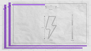
Working drawings should be made either by hand or using computer aided design (CAD) at this stage. Accurate dimensions and details of materials should be included to help manufacture your developed design idea.
Manufacture
Manufacture will use the information in your working drawing and the tools, processes, and materials available in your Technology and Design workshop.
You must learn how to use the tools and machines safely before manufacturing your product.
Test and evaluate
Your finally manufactured design solution will be tested on how it meets the design specification.
Ask questions like:
How well does it function?
Does it work reliably?
Can it be used safely?
What modifications would you make to your design?
Alex is having trouble keeping her mobile telephone safe when riding on her mountain bike
Design opportunity
2. Design a phone holder for use on a bicycle.
Design brief
3. Consideration of mobile phone holders on the market. Investigation of possible materials.
resherch
4. The developed mobile phone holder should:
hold one phone securely,
be made of plastic,
allow the phone to be used while holding the phone,
be attractive to teenage phone users
Design specification
5. Sketches of possible solutions with annotations.
Ideas generation
6. Working drawings with dimensions
Development of final solution
7. Use of a workshop including materials, tools, and resources.
manufacture
8. Consideration of how well the manufactured solution meets the design specification
Test and evaluate
product analysis
Analysis of existing products is an increasingly important element of project research within the design process. There are several reasons for this:
Research from analysing existing products can be used to inform your design specification and ideas.
It can help you work out the cost of manufacturing a product, including the materials needed and machinery required.
You will learn more about what already exists, which will help you develop products that meet the needs of end users better.
Product analysis
02:51
Video helping with analysing products for their aesthetic appeal and their ergonomic considerations (product comparison), and the evaluation of products compared to their design brief and product specification.
Analysis points of comparison between products may include:
Figure caption,
Function - What is the function and purpose of the product? How well does it work? Could it be improved?
Size - What is the size of the product? Is it comfortable to use? Is it a similar size to other products with the same use?
Cost - How much did it cost to make? How much does it cost to buy? Is it considered good value by the consumer?
Materials and components - What materials and components have been used to make the product? Why were these materials and components used?
Environment - Is the product sustainable and/or environmentally friendly? Is it recyclable? Can it be easily repaired rather than thrown away?
Aesthetics - What does the product look like? What is the colour, texture, pattern and decoration of the product?
Ergonomics (Human Factors) - is the product designed in a way to make it easy to use. Shape, size, weight, position of buttons and controls are all aspects that contribute to a product having good ergonomic design.
Product Comparison: Car Mobile Phone Holders

Example
| Phone Holder 1 | Phone Holder 2 |
|---|---|---|
Function | The mobile phone is held in place by a magnet. The phone can tilted by 40 degrees and rotated to portrait or landscape. | The mobile phone is held in place by a clamping mechanism. Then phone can be tilted by 30 degrees and rotated to portrait or landscape |
Size | The holder itself is 50mm tall and has a footprint of 40mm x 40 mm | The phone holder is 80 mm tall. The overall width is 110mm and length is 110mm. The mounting footprint is 60mm x 60mm |
Cost | £12.00 | £8.00 |
Materials and Components | Made from plastic with a magnet for phone attachment and an adhesive pad for desk mounting. | Made from entirely from plastic with a rubber suction cup for desk mounting. |
Environment | Materials can be recycled. Mounting pad needs to be replaced if holder is moved. | Materials can be recycled. Mounting suction cup is reusable when moving holder |
Aesthetics | Attractively designed and compact is size | A little large and not very attractive |
Ergonomics | Phone can easily be placed or removed with one hand. | Placement and removal with one hand can be difficult. |
During the research stage, evaluating existing products againstperformance criteria will aid in the writing of a refined brief and specification. Below is an example of an evaluation that compares two mobile phones.
Performance criteria | Mobile phone A | Mobile phone B |
|---|---|---|
Cost | RRP £350.00 | RRP £99.00 |
Size | Length = 130 mm, Width = 73 mm, Thickness = 7 mm | Length = 90 mm, Width = 65 mm, Thickness = 11 mm |
Weight | 77 g | 86 g |
From this comparison, it is possible to draw a number of conclusions.
Cost - Mobile phone A is more expensive than mobile phone B.
Size - Mobile phone A is longer and wider than mobile phone B. Mobile phone A also has a bigger screen, which means more information can fit on the screen. However, mobile phone B is 4mm thicker than mobile phone A.
Weight - Considering that the overall size of mobile phone A is bigger, it is 9 g lighter than mobile phone B.
test yourselfs
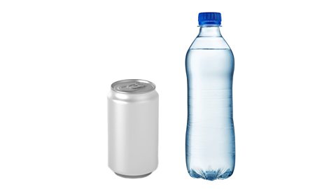
The table below compares an aluminium drinks can and a polyethylene terephthalate (PET) drinks bottle on a variety of performance criteria:
Performance criteria | Aluminium drinks can | PET drinks bottle |
|---|---|---|
Cost of manufacture | £0.03 | £0.09 |
Function | Hold liquid without leaking. Single-use container. | Hold liquid without leaking. Contents visible through bottle. Can be resealed and reused. |
Volume | 300 ml | 500 ml |
What conclusions about cost, function and volume can be drawn from this comparison?
From this comparison, it is possible to draw a number of conclusions.
Cost - The aluminium drinks can is cheaper to manufacture compared with the PET drinks bottle. The PET drinks bottle is three times more expensive to manufacture.
Function - Both containers hold liquid without leaking; however, the contents of the PET drinks bottle can be seen, which is an advantage as the user can see how much of the drink is remaining. Another advantage of the PET drinks bottle is that it can be resealed, meaning it does not have to be consumed in one go and so can be reused.
Volume - The aluminium drinks holds 200 ml less liquid than the PET drinks bottle. One reason for the increased manufacturing cost might be that the PET drinks bottle can hold more liquid.
Sketching and modelling
Designers use many techniques to create products and solve problems. Sketches are used at the early stages with annotation to illustrate the designer’s thoughts. Development of the final design will involve creating working drawings and parts lists to enable a third party to manufacture the design.
Modelling can be used throughout the design stages to help illustrate, evaluate and refine design ideas.
03:09
Video Transcript
Freehand sketches
Freehand sketching is the quickest way of getting your initial designs on paper before an idea is forgotten. Freehand sketches are often done without a ruler or template and instead are produced quickly and freely.
Annotation can be added at any point to show key parts, sizes, materials, components and construction. The use of shading, colour and different viewpoints can be an easy way of communicating initial ideas.
Isometric drawings
Isometric drawings are commonly used in technical drawing to show an item in three dimensions (3D) on a page. Isometric drawings, sometimes called isometric projections, are a good way of showing measurements and how components fit together.
There are three main rules to isometric drawing:
horizontal edges are drawn at 30 degrees
vertical edges are drawn as vertical lines
parallel edges appear as parallel lines
Isometric drawings are used to show a graphical representation of a 3D object. They are used by architects and engineers to communicate their ideas to the client and manufacturer, showing the product or design to to scale.
Two cubes drawn in isometric:
Modelling of design ideas
Modelling can be time-consuming and expensive, but a physical model allows a person to see and handle a product unlike viewing it on a screen through computer aided design (CAD).
Computer aided manufacture (CAM) models made on a 3D printer using a CAD drawing are very accurate but also expensive, time-consuming and limited to 3D-printable materials.
Product designers can use easy-to-form and easily accessible materials, eg balsa, jelutong and cardboard, to create cheap models quickly and cheaply.
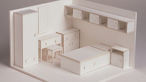
Image caption,
A 3D model of bedroom design
Models can be used to help:
test the solutions functionality and whether the design is fit for purpose before selection for development and manufacture
others, including a client, to see how the solution will look and provide feedback
plan for manufacture, including suitable sizes and materials

02:22
Modelling and prototyping to help with the design process
Formal drawing and computer aided design (CAD)
( clik me for vidios https://www.bbc.co.uk/bitesize/topics/ztcrjfr/articles/zw8y9ty#zjwqp9q)
Formal drawings
Formal drawings are a more precise style of drawing. They can be produced by hand or with computer aided design (CAD) packages.
Formal hand drawings use tools such as rulers and set squares to ensure accuracy and neatness.
Using computer aided design (CAD) allows the user to quickly make changes, and the drawings can be digitally shared and copied with ease.
Formal drawings are used when showing an idea to a client, showing measurements or getting feedback from a user group.
Formal drawing of a toy car
Description | Materials | Part | Length | Height | Quantity |
|---|---|---|---|---|---|
Top lid | Acrylic | 1 | 220mm | 200mm | 1 |
Left side | Plywood | 4 | 321mm | 210mm | 2 |
Front window | Acrylic | 6 | 200mm | 90mm | 1 |
Front top | Plywood | 2 | 200mm | 101mm | 1 |
Front | Plywood | 3 | 200mm | 120mm | 1 |
Wheel | Plywood | 5 | 70mm | - | 4 |
Back | Plywood | - | 200mm | 210mm | 1 |
Working drawings
Design and development involves creating working drawings and parts lists to enable a third party to manufacture the design.Working drawings are sent from a designer to a manufacturer to enable them to build a product.
Exploded diagrams
Exploded diagrams show how a product can be assembled and how the separate parts fit together, with dotted lines showing where the parts slide into place. The diagrams also show components that would usually be hidden in a solid drawing.
Exploded diagrams can take the place of detailed written instructions, meaning they can explain the construction of something without the barrier of different languages. They are widely used as instructions for self-assembly furniture.
Elevations
Elevations are the sides of an item you can see on the drawing, e.g. front elevation or side elevation. The top is referred to as the ‘plan’. These drawings enable detailed measurements to be added for every section of the product.
This isometric drawing shows the plan and front and side elevations of the shape.
Horizontal lines should be drawn at a 30° angle
Vertical edges should be drawn as vertical lines
Parallel edges drawn as parallel lines
You can find more information about isometric drawings in sketching and modelling
Orthographic projections
Orthographic projections are working drawings in either a first or third angle projection and show each side of a design. They are used to show an object from every angle to help manufacturers plan production.
Starting with a front view of a product, construction lines show where areas join and are used to draw a side and plan (top) view, ensuring that the drawing is accurate from all angles. These drawings are to scale and must show dimensions.
Third angle projections
Third angle projection is an accurate method to produce ‘working drawings’. The position of the plan, front and side views are important in this method of drawing.
In third-angle projection, the view of a component is drawn next to where the view was taken.
What you see from the right would be drawn on the right and what you see from looking at the top will be drawn above.
Figure caption,
In a third angle projection the plan view is above the side view
Figure caption,
The symbol that indicates Third Angle Projection is used
First Angle Projections
In first-angle projection, the view is drawn on the other end of the component, at the opposite end from where the view was taken.Symbol for First Angle Project
Figure caption,
The symbol that indicates First Angle Projection is used
Standard lines
Orthographic projections have a set of standard lines to show different aspects of the diagram. These lines allow complex shapes to be drawn simply in 2D.
Figure caption,
Standard lines used in an orthographic drawing
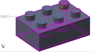
Computer aided design (CAD)
Computer aided design (CAD) is the use of computer software to design new products in both in 2D and 3D. Some of the software commonly used in schools is 2D TechSoft and SolidWorks for 3D designs
03:18
Video Transcript
CAD software allows you to easily visualise what a product is going to look like when it is made. The designs made on this software can be easily transferred to machines such as a laser cutter of 3D printer. This is known as Computer aided manufacture (CAM).
Advantages of CAD | Disadvantages of CAD |
|---|---|
Ideas can be drawn and developed quickly | Expensive to set up |
Designs can be viewed from all angles and with a range of materials | Needs a skilled workforce |
Some testing and consumer feedback can be done before costly production takes place | Difficult to keep up with constantly changing and improving technology |
It becomes easier to design and test a range of ideas | Computers can fail |
Manufacturing
Manufacturing
Tools and Processes
Manufacturing workshops provide access to a wide range of tools and machines to manufacture products. Workshop tools and machines, used safely, can be used to mark, cut, shape, form and finish materials to a high standard.
03:11
Video Transcript
Tools for woodwork - marking out, cutting, shaping
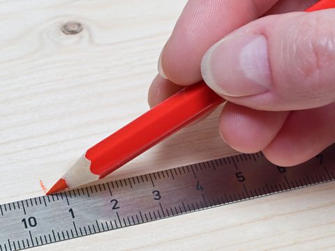
300mm Steel rule
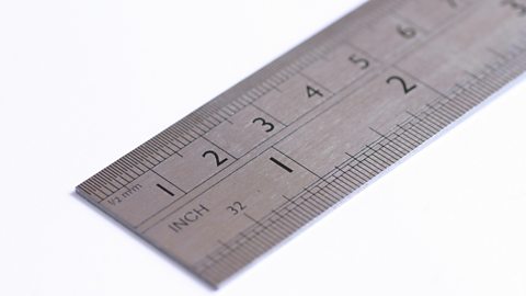
Used for general measuring and marking out.
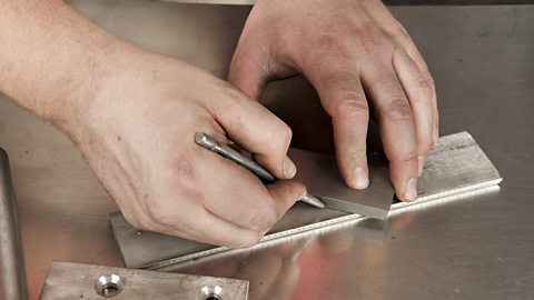
Try Square
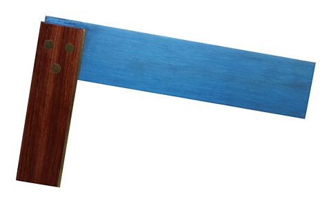
Used for marking lines at right angles to an edge on wood. Can also be used to check for ‘squareness’
Bench Hook
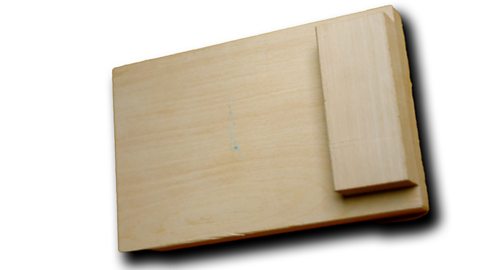
Used with the woodworking vice and the tenon saw when cutting wood. A bench hook enables a piece of wood to be held firmly in position during cutting.
Marking Gauge
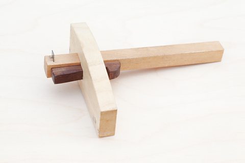
Used to mark lines parallel to an edge on wood.
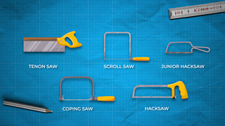
Tenon Saw
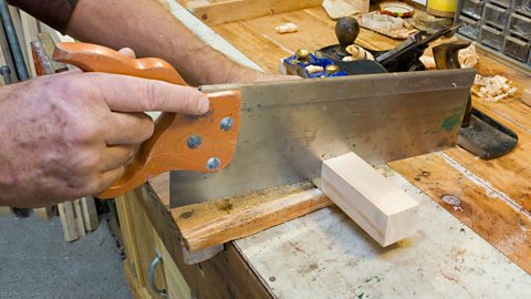
Used for cutting straight lines in wood, also used for cutting wood joints.
Coping Saw
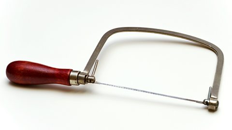
Used for cutting curves in wood and plastic.
Tools for Metalwork - marking out, cutting, shaping
300mm Steel rule
Used for general measuring and marking out.
Scriber
Used for marking out on metal, sometimes used with ‘marking blue’ to make the marks easier to see. Marking blue coats the metal and is scratched off with the scriber
Centre punch
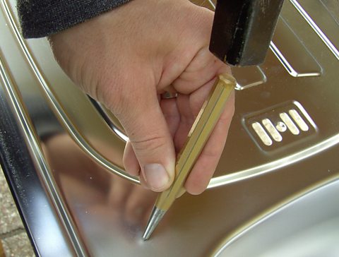
Used on metal to mark the position of a hole to be drilled. This then prevents the drill from slipping.
Files
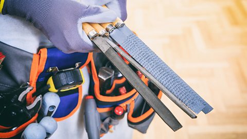
Used for shaping and removing waste material on metals and plastics. Available in a variety of shapes.
Hacksaw

Used for cutting straight lines in metal.
Junior hacksaw
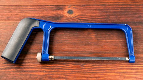
A smaller version of a hacksaw, used in enclosed spaces, precise cuts and for smaller pieces of metal.
Workshop machines
Bandfacer
Figure caption,
A bandfacer is used to smooth the edges or shape wood and plastic. It is a large loop of sandpaper running through a machine at high speed
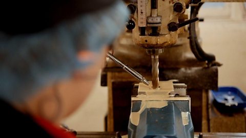
Pillar drill
Figure caption,
A pillar drill, pedestal drill or drill press is used to bore accurate holes in wood, metal or plastic. The drill is fixed and is raised and lowered using the feeding handle.
Polisher
Figure caption,
A polisher is used to shine and smooth metal and plastic.
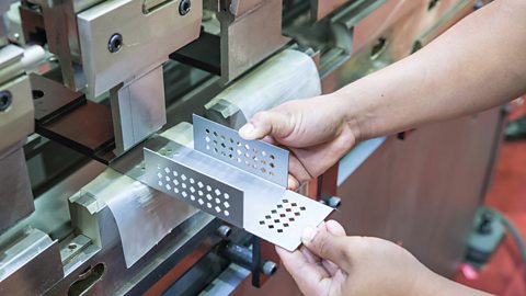
Vacuum Forming
02:59
This video explains the processes involved with Vacuum Forming, the easiest way to make hollow plastic mouldings which can be used in a wide variety of RMT design/make projects.
Video Transcript
Lower mould into vacuum former.
Heat the plastic until soft.
Bring the mould up into the plastic using the lever.
Switch on the vacuum to suck out all the air.
Switch off vacuum and remove the plastic.
Remove moulds – cut away excess plastic.
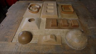
Sometimes talc can be dusted on the mould to help it drop out with ease. A good vacuum-formed product will only be possible if a good mould has first been made. The mould must have a draft angle, so it doesn’t get stuck in the plastic. A draft angle is a slant that on each side of a vacuum moulded part. This helps with releasing the part from the mould.
Line Bending
A line bender has a heated wire that provides heat, concentrated to just a few millimetres wide. The wire heats plastics along a line so they can be bent. Once the plastic softens, it can be bent easily into shape around a former before being left to cool.

01:49
Line bending is a technique used to make precise folds in plastic components. The process is demonstrated using a strip heater and a hot wire line bender. Acrylic is used in this demonstration but the process can be used for a variety of thermoplastics.
Video Transcript
Metal Folding
Sheet metal can be easily bent using a manual folding machine also known as a ‘Box Pan Folder’. The piece of sheet metal is first clamped into position. The user then pushes the handle upwards, and the sheet metal is shaped to the required angle.
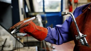
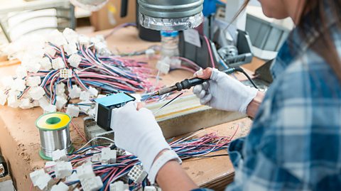
Soldering
How to solder
Soldering is a way to join metal parts, often electrical components, by heating a filler metal called solder until it melts. When the solder cools, it fuses the components together.
All components must be clean and grease free.
Heat both parts of the joint to 200°C with a hot soldering iron - for at least 10 seconds.
Apply the solder, allowing it to run into the joint.
Allow it to cool without movement of the joint.
Use a heat sink when soldering diodes and transistors.

Safe soldering
Never touch the tip of the soldering iron. They are very hot and will give you a nasty burn
Take great care to avoid touching the mains flex with the tip of the iron. An ordinary plastic flex will melt immediately if touched by a hot iron and there is a serious risk of burns and electric shock.
Always return the soldering iron to its stand when not in use. Never put it down on your workbench, even for a moment!
Work in a well-ventilated area. The smoke formed as you melt solder is mostly from the flux and can be quite irritating.
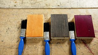
Finishing materials
Finishes are usually applied to products for two reasons, firstly to protect them (e.g. from rusting/rotting), secondly to make them look more aesthetically pleasing.
The table below outlines the different finishes that can be applied to each type of material.
| Wood | metal | plastic |
|---|---|---|---|
paint | ✔ | ✔ | |
polish | ✔ | ✔ | |
plastic dip coat | ✔ | ||
galvanising | ✔ | ||
varnish | ✔ | ||
oil | ✔ |

02:34
Finishing Metal
Video Transcript
02:57
Finishing plastic
Video Transcript
02:44
Finishing wood
helth and safty
Manufacturing
Health and Safety
Manufacturing safely is very important in all technology workshops. The safe use of tools, machines, and equipment and following rules, signs and procedures will help prevent workshop accidents.
02:48
Safety rules are put in place to keep both you and others safe when in the workshop.
Video Transcript
Current safety signs
In the workshop there are many types of safety signs. These are split into four groups: mandatory, prohibition, hazard and safe condition.
Sign
Type: Prohibition
Prohibition
Image gallerySkip image gallery

Image caption,
Meaning: What you must NOT do

Image caption,
No naked flames

Image caption,
Do not put fingers in machinery
1 of 3
Previous imageNext image
Slide 1 of 3, Red circle bisected by diagonal red line, Meaning: What you must NOT do
End of image gallery
Mandatory
Image gallerySkip image gallery

Image caption,
Meaning: What you MUST do

Image caption,
You must wear ear protection

Image caption,
You must wear eye protection
1 of 3
Previous imageNext image
Slide 1 of 3, Blue circle, Meaning: What you MUST do
End of image gallery
Hazard or danger warning
Image gallerySkip image gallery
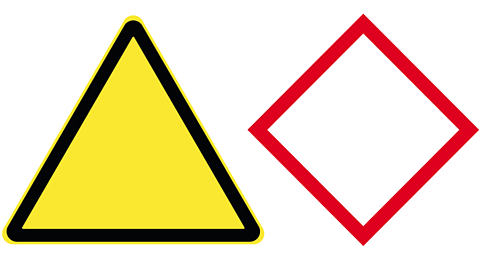
Image caption,
Meaning: Warns of a risk or danger
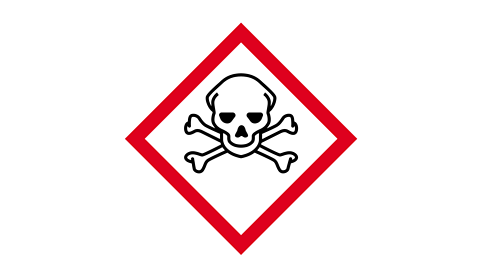
Image caption,
Danger - toxic or poison
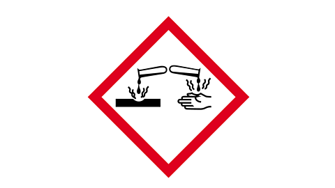
Image caption,
Warning - corrosive material
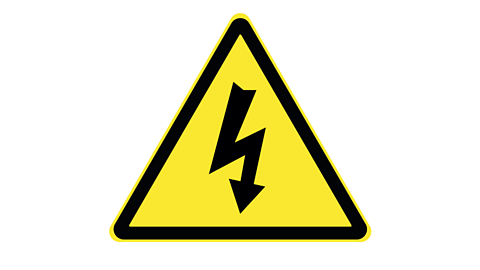
Image caption,
Warning - electrical hazard
1 of 4
Previous imageNext image
Slide 1 of 4, Meaning: Warns of a risk or danger, Meaning: Warns of a risk or danger
End of image gallery
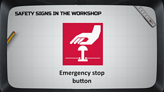
Condition
Image gallerySkip image gallery

Image caption,
Meaning: Safety facilities are nearby

Image caption,
First Aid is here

Image caption,
Emergency eye wash station
Image caption,
Emergency stop button location
Note: The sign used for location of an emergency stop button is white on a red square.
1 of 4
Previous imageNext image
Slide 1 of 4, Green square, Meaning: Safety facilities are nearby
End of image gallery
Risk assessments
What is a risk assessment and how it can be used.
A risk assessment is a careful examination of the things that could cause harm to people, and helps you to put precautions in place to prevent injury and ill-health.
A risk assessment consists of three sections – hazard, risk, and control measure.
Below shows a picture of what a typical risk assessment could look like.
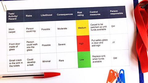
Image caption,
A typical risk assessment
How to assess risks
You must first identify any potential hazards This will be something that could hurt you or someone else, and its source. For example, a soldering iron could cause burns.
Secondly, you must state what the risk is. What is any possible way you could get hurt? In this example, it could be touching the tip of the soldering iron when moving it. Moving it would be the reason you or someone else would get burned.
Then, you must think of a control measure. This means asking yourself, how to avoid getting hurt? If the risk, like this example, is a risk of getting burned by a soldering iron, the control measure would be to allow the soldering iron to cool before attempting to move it.
Personal protective equipment (PPE)
How to Dress Safely in the Workshop
Personal protective equipment (PPE) must be worn when it is instructed to do so. Signs may be shown in the workshop showing you what items of protective equipment need to be worn when operating machines.
Examples of PPE
protective gloves and aprons for working with heat
goggles must be worn where there may be dust or splashing
ear protection when using or working around noisy equipment
dust mask when spray painting or routing wood
materials
Manufacturing Materials
Selecting the most suitable material for your project is very important. Carefully consider the physical properties, working properties, cost and sustainability of each material.
04:14
Video Transcript
Wood- properties and applications
Softwoods
Softwoods come from coniferous trees. These often have needles, and stay green all year round - they do not lose leaves in the autumn. Softwoods tend to grow quicker which means that they are cheaper to buy as they will quickly be replenished.
Softwood | Physical Properties | Working Properties | Uses |
|---|---|---|---|
Pine | Pale coloured with aesthetically pleasing grain | Lightweight and easy to form | Used for furniture and decking |
Cedar | Lightweight and pale colour | More expensive than pine but not as strong | Used for fencing and decking |
Image gallerySkip image gallery
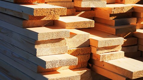
Image caption,
Softwood - pine

Image caption,
Softwood - cedar
1 of 2
Previous imageNext image
Slide 1 of 2, Pine planks stacked as lumber, Softwood - pine
End of image gallery
Hardwood
Hardwoods come from deciduous trees, which have large flat leaves that drop in the autumn. Hardwoods tend to grow slowly so are therefore more expensive as they take longer to be replenished.
Hardwood | Physical Properties | Working Properties | Uses |
|---|---|---|---|
Beech | Slight pink tint, close grain | Tough, durable and smooth to finish | Used for handles on tools and furniture |
Mahogany | Dark-reddish colour, very close grain | Cuts and polishes easily, gives a fine finish | Used for high-quality furniture |
Oak | Moderate-brown colour with unique and attractive grain markings | Tough and durable, polishes well | Used for quality furniture |
Image gallerySkip image gallery
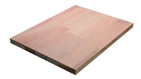
Image caption,
Hardwood - beech

Image caption,
Hardwood - mahogany

Image caption,
Hardwood - oak
1 of 3
Previous imageNext image
Slide 1 of 3, Glued beech board, Hardwood - beech
End of image gallery
Manufactured boards – overview
Manufactured boards are usually made from timber waste and adhesive.
Manufactured Board: | Physical Properties | Working Properties | Uses |
|---|---|---|---|
Medium-density fibreboard (MDF) | Smooth and light brown | Smooth and easy to finish, absorbs moisture so not suitable for outdoor use | Used for general carpentry work and flat-pack furniture |
Plywood | Layers of veneer glued at 90 degree angles for strength, aesthetically pleasing outer layer | Easy to cut and finish, can be stained or painted | Used for furniture, shelving, construction and toys |
Image gallerySkip image gallery
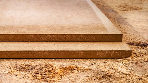
Image caption,
Manufactured boards - medium density fiberboard (MDF)

Image caption,
Manufactured boards - plywood
Metals
Ferrous metals - properties and applications
Ferrous Metal | Physical Properties | Working Properties | Uses |
|---|---|---|---|
Mild steel | An alloy that is grey and smooth, rusts if not protected | Ductile and tough, easy to form | Used for bike frames and fixings like nuts, bolts, screws and nails |
Stainless steel | Corrosion resistant (will not rust), tough, resists wear | Difficult to cut | Used for kitchenware such as cutlery, pots, pans and sinks |
Ferrous metals
Image gallerySkip image gallery
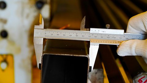
Image caption,
Ferrous metals - mild steel
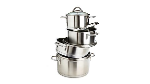
Image caption,
Ferrous metals - stainless steel
1 of 2
Previous imageNext image
Slide 1 of 2, Mechanic uses vernier to measure the size of the mild steel box section, Ferrous metals - mild steel
End of image gallery
Non-ferrous metals - properties and applications
Non-Ferrous Metal | Physical Properties | Working Properties | Uses |
|---|---|---|---|
Aluminium | Light grey with a matt finish | Lightweight but strong and ductile | Used for drink cans, kitchen utensils and some parts in transport |
Copper | Rose coloured, polishes well but can oxidise to a green colour | Good electrical conductor, can be polished, welds easily | Used for plumbing parts and electrical wires |
Non-ferrous metals do not contain iron and are not magnetic. They do not rust.
Alloys
An alloy is a mixture of two or more metals to create a new material with improved properties.
Some examples of alloys include: brass and stainless steel.
Brass is made from a mixture of copper and zinc. Brass is commonly used to make electrical components and instruments.
Stainless steel is made from a mixture of carbon and iron. Stainless steel is often used for kitchen utensils and cutlery.
Non-ferrous metals
Image gallerySkip image gallery
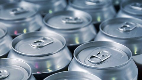
Image caption,
Non-ferrous metals - aluminium

Image caption,
Non-ferrous metals - copper
1 of 2
Previous imageNext image
Slide 1 of 2, Collection of aluminium drinks cans, Non-ferrous metals - aluminium
End of image gallery
Plastics
Thermoplastics - properties and applications
Thermoplastics can be reformed when heated, and therefore can often be recycled.
Thermoplastic | Physical Properties | Working Properties | Uses |
|---|---|---|---|
Acrylic | Hard, brittle, shiny, available in a wide range of colours | Resists weather well, can be cut, folded and polished well, scratches easily | Used for car lights, display signs and baths |
Rigid Polystyrene | Available in a wide range of colours | Lightweight, and can be easily shaped | Used for food containers and cheap toys |
Thermoplastics can be reformed or reshaped when heated, and can often be recycled.
Thermosetting - properties and applications
Thermosetting plastic can only be formed once as it cannot be reheated and therefore cannot be recycled.
Thermosetting plastic | Physical Properties | Working Properties | Uses |
|---|---|---|---|
Polyester resin (PR) | A resin and a hardener, sets clear and smooth | Strong, heat resistant and good electrical insulator | Used for garden furniture and glass reinforced boats and cars |
Plastics
Image gallerySkip image gallery

Image caption,
Plastics - thermoplastics - acrylic
Image caption,
Plastics - thermoplastics - rigid polystyrene - high impact polystyrene (HIPS)
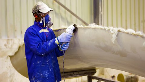
Image caption,
Plastics - thermosetting plastic - polyester resin
1 of 3
Previous imageNext image
Slide 1 of 3, Transparent solid acrylic block, Plastics - thermoplastics - acrylic
End of image gallery
Computer aided manufacture (CAM)
Traditional methods of production involve drawing designs by hand, creating a number of prototypes and using humans to manually produce goods or operate machinery. Some products still benefit from these methods of production, such as those with a reputation or tradition for being hand made.
However new methods of CAD and CAM offer the benefits of being cheaper, quicker and more efficient.
Computer aided design
Computer Aided Design (CAD) drawing allows components to be manufactured using Computer Aided Manufacture (CAM). Computer aided manufacture is very fast and accurate and requires less human intervention.
Video Transcript
Computer aided manufacture (CAM)
Computer aided manufacture (CAM) involves using computers to control machines during the production of goods. By using CAM, designs can be sent to CAM machines such as laser cutters, 3D printers and milling machines. Design files must first be drawn up using computer aided design (CAD) software.
laser cutting is when a high-powered laser is used to cut, etch or engrave a material.
Video Transcript
Image gallerySkip image gallery
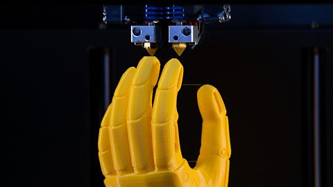
Image caption,
3D printed model of a hand
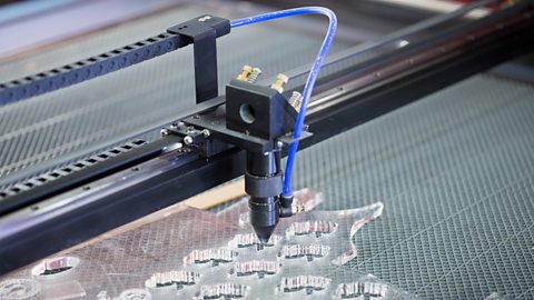
Image caption,
A laser cutter
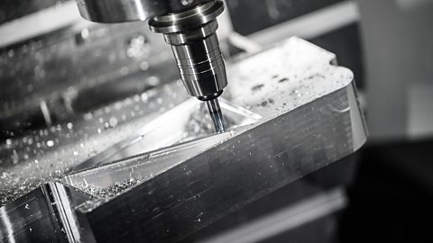
Image caption,
A milling machine
1 of 3
Previous imageNext image
Slide 1 of 3, A yellow plastic model of a prosthetic hand being 3D printed., 3D printed model of a hand
End of image gallery
Advantages and disadvantages of CAM
Using computer aided manufacture (CAM) comes with some advantages and disadvantages:
Advantages | Disadvantages |
|---|---|
Machines can run 24/7 | The machines are expensive to set up |
Produces products that are identical – accuracy | Computers and machines can fail |
Less material is wasted | Engineers need to be highly skilled |
control systems
Electronic control systems
Electronic components are chosen based on factors such as their function. It is important to choose a component that is best fit for purpose.
You can learn about Voltage, Resistance, Current and Ohms law here
03:46
Video Transcript
Conductors and insulators
Conductors
Most metals allow electrical current to flow through them easily because they have a low resistance.
The process of electrical current flowing through a wire is called conduction, and materials that conduct are called conductors.
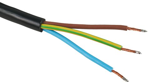
Image caption,
Most metals are good electrical conductors. Electrical cables are made from the metal copper.
Insulators
Most non-metals, like plastic, glass and rubber do not allow electrical current to flow through them easily.
They have a high resistance and are called insulators.
Non-metals are usually poor conductors because they have very few free electrons. This makes it difficult for electrical current to flow through them. Insulators are materials that don’t allow an electrical current to flow through them.

Image caption,
Mains electrical cables contain a metal wire, covered in plastic insulation. The case of the plug is usually made of plastic or rubber too.
Making a printed circuit board (PCB)
Image gallerySkip image gallery
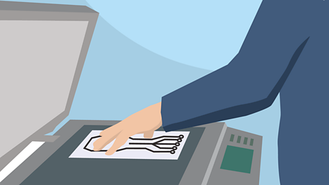
Image caption,
Copy
Photocopy or trace a copy of the circuit onto an acetate sheet to make a mask of the circuit. This is called the PCB Artwork.
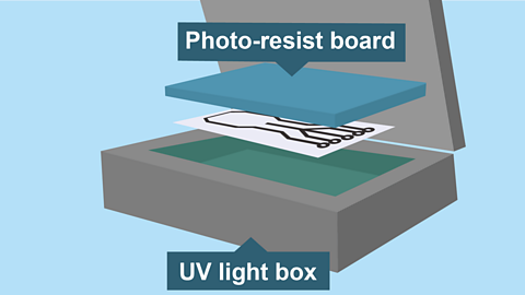
Image caption,
Expose
Place the mask into an ultra-violet light box and set the photo-resist board on top. Close the box and expose for four minutes.
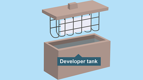
Image caption,
Develop
Place the board carefully into the developing solution (Sodium Hydroxide) to remove all the film except where the tracks are. Once you can see the copper tracks rinse under water.
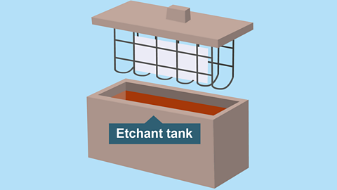
Image caption,
Etch
The chemical (Ferric Chloride) is heated to about 50°C. It will dissolve any unprotected copper leaving a PCB with copper tracks on one side.
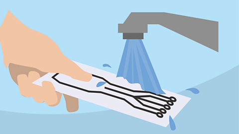
Image caption,
Rinse
Rinse with water.
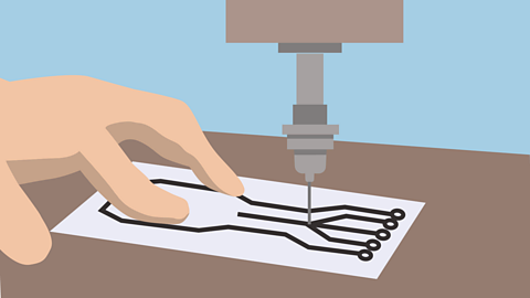
Image caption,
Drill
The last stage is drilling the holes for the components. A small PCB drill is used for this purpose.
1 of 6
Previous imageNext image
Slide 1 of 6, Hand placing a drawing of a circuit on the glass of a photocopier, Copy Photocopy or trace a copy of the circuit onto an acetate sheet to make a mask of the circuit. This is called the PCB Artwork.
End of image gallery

Care is needed as a good PCB can be ruined by careless drilling.
Once the holes are drilled the PCB can be populated and the components soldered in place.
Constructing a circuit diagram
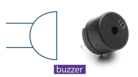
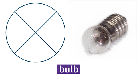
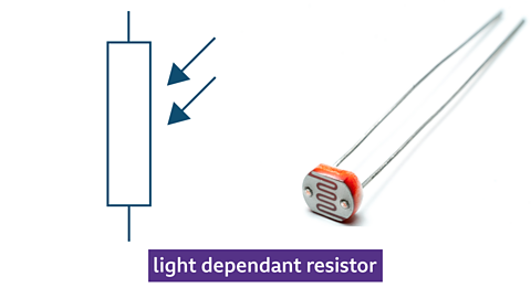
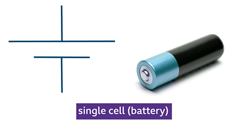
When constructing a circuit diagram, symbols are used to represent the different components, this makes it easier and quicker to draw rather than drawing detailed components.
Commonly used components and their symbols
Image gallerySkip image gallery


1 of 9
Previous imageNext image
Slide 1 of 9, Symbol and photo of electronic buzzer,
End of image gallery
Circuits can be drawn on the computer and symbols can be dragged onto a page and connected with lines. This allows the circuit to be tested before it gets made into a printed circuit board.
Figure caption,
A schematic of a simple circuit showing how different components are connected together, including a battery and a switch.
Basic electronic components
Electronic systems can be split up into three sections, these are:
Input → Process→ Output
Input
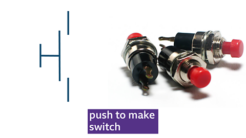
Input devices allow systems to understand changes in the environment around them. It is a device used to input data or information. A switch is an example of an input device.
Switches can be used to turn circuits on and off.
Example: A push-to-make (PTM) switch allows current to flow (or a signal to be passed on for processing) when pressed - therefore ‘making’ the circuit. A push-to-break (PTB) switch does the reverse and ‘breaks’ the circuit.
Figure caption,
Push-to-make (PTM) and push-to-break (PTB) switch diagrams
Process
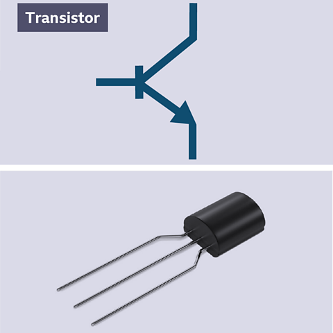
Process devices take the signal from the input stage of a system and act on it by changing it in some way.
Transistors are an example of a processing device, and are a special type of switch. When a small amount of volts is applied to the Base leg, a large current is allowed to flow from the Collector to the Emitter.
Output
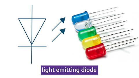
Output devices allow a system to present information back into the ‘real’ world. Examples can be seen everywhere, from car indicators to doorbell buzzers or lights. Examples of output devices include light emitting diodes (LED’s), buzzers and motors.
LED’s are the most common component used for producing light. The long leg is the positive (+) side, known as the anode, and the short leg is the negative (-) side, known as the cathode. If put into a circuit the wrong way round it will not work.
Figure caption,
Light emitting diode (LED)
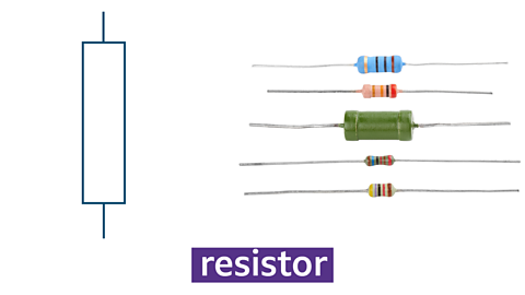
Resistors
Resistors are another example of a processing device. Resistors are used to restrict the flow of current around a circuit and can prevent damage to components.
Resistors used in electrical circuits have a tolerance of how much power they allow into a circuit. When reading the value of a resistor, it must be held with the gold or silver band to the right - this is the tolerance band.
Figure caption,
The above picture shows yellow (4), violet (7) and red (× 100) = 47 × 100 = 47,000 ohms (Ω)
Band 1 = First Number
Band 2 = Second Number
Band 3 = Number of Zeros (Multiplier)
Band 4 = Tolerance
The amount of tolerance a resistor has is shown with the colour of the fourth stripe and is usually silver or gold.
Silver = +/- 5%
Gold = +/- 10%
Resistors in series:
Resistors are used to restrict the flow of current around a circuit and can prevent damage to components.
Resistors in series means that they are arranged in a way that is one after the other.
Figure caption,
Resistors in series
When calculating resistors in series the following calculation is used.
𝑅𝑇𝑜𝑡𝑎𝑙=𝑅1+𝑅2
Potential divider rule
A voltage divider does as its name suggests - it divides a supply voltage across two resistors which are connected in series.
The supply voltage is divided in the ratio of the resistances in the voltage divider.
𝑉=Supply Voltage×𝑅1𝑅1+𝑅2
If one of the resistances in a voltage divider increases, then the voltage across that resistor also increases. This may appear to be the wrong way round but it is because of the way the resistors are connected together.
The circuit of a voltage divider may be drawn with the two resistors vertical, not horizontal. If there are two resistors in series across a voltage source, then the circuit is a voltage divider.
Question
A voltage divider consisting of two 500Ω resistors is connected across a 9V battery. Calculate the voltage across one of the resistors.
Show more
Electronic control systems – electronic quantities
How electronic quantities function in a circuit
Current – the flow of electrons. The number of electrons passing a given point in one second. Current is measured in Amps and milliamps (A).
Voltage – the force that makes electrons flow.Voltage (v) is measured in Volts and millivolts (V).
Resistance - When a material resists the flow of electrons.Resistance is measured in ohms, kilo-ohms, mega-ohms (Ω).
Ohm's law
The quantities voltage, current and resistance are linked by the relationship:
Voltage = Current × Resistance
This relationship is called Ohm's Law. We usually write Ohm's Law as;
V=IR
The symbol for resistance is R, it is measured in ohms (Ω).
The symbol for voltage is V, it is measured in volts (V).
The symbol for current is I, it is measured in amperes (amps) (A).
If given any two of these quantities, you will be able to work out the third.
The equation can be re arranged to work out any of the three quantities.
The triangle below can help you to remember the relationship.
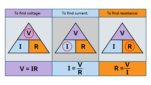
Image caption,
V is equal to I multiplied by R; I equals V divided by R; and, R equals V divided by I.
Mechanical control systems
Mechanical devices can change one form of force to another. All moving parts work on some sort of mechanism. Mechanical systems all involve an input, process and produce an output.
03:59
Video Transcript
Types of motion
Mechanical devices all have an input motion, which transforms into force to make an output motion.
The four types of motion are:
linear
rotary
reciprocating
oscillating
Examples of motion types
Linear

Movement in a straight line.
Train moving down a track.

Rotary

Motion that moves around an axis or pivot point.
Wheels on a bicycle.

Reciprocating

Repeated movement up and down or back and forth
Sewing machine

Oscillating

Curved movement backwards and forwards – movement that swings.
Clock pendulum

Levers
Levers have three main parts:
Effort - the amount of force applied by the user, also referred to as the input
Fulcrum - where the lever pivots
Load - the weight that needs to be moved, also referred to as the output
There are three different types of levers. They are chosen for their ability to produce the most mechanical advantage for a particular task. The effort, fulcrum and load are arranged in different orders, the class of lever depends on which section of the lever is in the middle.
Class 1 lever
A class 1 lever has the Fulcrum in the middle. E.g., Using a crowbar.
Figure caption,
A class 1 lever - showing the fulcrum in the middle
Class 2 lever
A class 2 lever has the Load in the middle. E.g., A wheelbarrow.
Class 2 lever
Class 3 lever
A class 3 lever has the Effort in the middle. E.g., Using tongs
Mechanical advantage is the amount of help you get using a machine in comparison to doing something with just human effort, and it is created by levers.
Cams and followers
a cam - attached to a crankshaft, which rotates
a follower - touches the cam and follows the shape, moving up and down
Cams
Cams come in a variety of different shapes. Each shape leads to the follower producing a different outcome and are therefore used for different applications.
There are four main shapes of cams. Depending on the use and the desired output movement different shapes can be used.
Pear cam
Circular cam
Heart shaped cam
Drop cam
Followers
Followers also come in a variety of different shapes the three main types are flat, knife and roller.
Flat follower
Point or knife follower
Roller follower
Pulley and belt systems
Pulleys
Pulleys use mechanical advantage, similar to levers, to lift loads. Pulleys are wheel shaped with a groove that allows a cord or chain to sit inside the groove. A single pulley changes the direction of force, making pulling down easier than lifting up. Single pulley systems can be seen in cranes, lifting a bucket from a well, raising a flag or adjusting window blinds.
Figure caption,
A single fixed pulley has a mechanical advantage of one
One pulley doesn’t make a mechanical advantage, as the same amount of force is needed. However, if additional pulleys are added, a mechanical advantage is created. Using two pulleys together means you need half the force to lift.
Figure caption,
A system of two (or more) pulleys is often called a block and tackle
Belt drives transfer movement from one rotating pulley to another, each held on a shaft. Shafts and pulley wheels can be made out of any material, whereas pulley belts are generally made from a soft, flexible material such as rubber. Grooves on the pulleys and belts help them to grip and turn.

Image caption,
Grooves on a pulley and belt
Belts
Belts can be attached around different-sized pulleys to drive shafts to change speed. As with gears, the bigger the wheel, the slower the speed. The velocity ratio between two pulleys can be calculated.
Velocity ratio = diameter of the driven pulley ÷ diameter of the driver pulley
This can then be used to calculate the output speed.
Output speed = input speed ÷ velocity ratio
Example
A driven pulley has a diameter of 120 mm and a driver pulley has a diameter of 40 mm.
Velocity ratio = diameter of the driven pulley ÷ diameter of the driver pulley
= 120 ÷ 40 = 3 or 3:1
The smaller driver pulley turns three times to make the driven pulley turn once.
The output speed of the larger driven pulley can then be calculated using the information available - the input speed is 100 revolutions per minute (rpm) and the velocity ratio has been calculated as 3.
Output speed = input speed ÷ velocity ratio
= 100 ÷ 3 = 33 rpm
Gears
Gears are wheels with teeth around the outside, the simplest form of which is a spur gear. When several wheels are interlocked, they can transfer motion from one place to another, eg in some hand whisks or on bikes.

Gear trains are when two or more gears are joined together. In a simple gear train, the drive gear causes the driven gear to turn in the opposite direction.
Smaller gears with fewer teeth turn faster than larger gears with more teeth. This difference in speed is called the gear ratio.
Example
The driven gear has 60 teeth and the drive gear has 15 teeth.
Gear ratio = 60 ÷ 15
= 4
For each rotation of the drive gear, the driven gear would rotate four times.
Gear ratio = 4:1
This is known as gearing up. If the driven gear had 15 teeth and the drive gear had 60 teeth, the gear ratio would be 4:1 which is known as gearing down.
Large gear moving a small gear = Gearing up
Small gear moving a large gear = Gearing down
If the drive gear and the driven gear are separated by another gear, called the idler, they will move in the same direction.
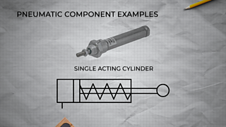
Pneumatic systems and control
Pneumatics looks at the use of compressed air to create a circuit. A pneumatic circuit is made up of an input, process, and output. Pneumatics are used in everyday life for example compressed air is used for airbrushes, dentist drills, lorry breaks and bicycle pumps.
03:18
Video Transcript
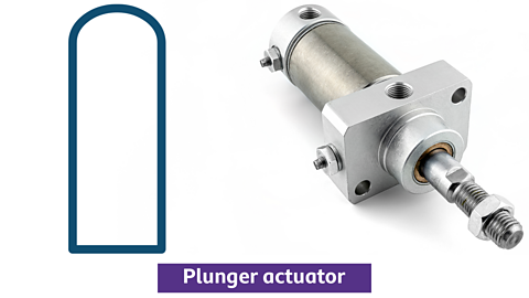
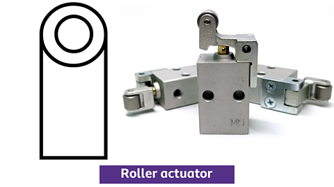
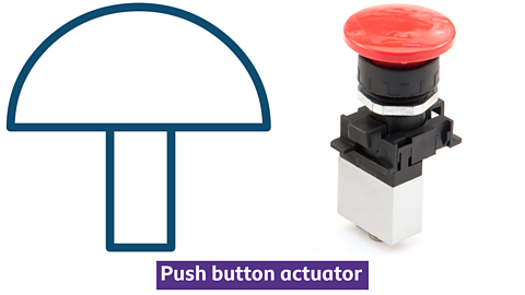
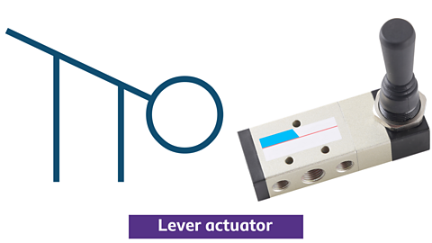
Actuators
An actuator acts like a switch in a pneumatic circuit – it allows you to turn the circuit on and off. Valves can be actuated using different methods.
Types of actuator
Image gallerySkip image gallery
1 of 4
Previous imageNext image
Slide 1 of 4, Plunger actuator symbol with photograph of plunger actuator,
End of image gallery
The methods of operation shown above are used to actuate a 3/2 valve. This means they can be used to turn a circuit on or off.
3/2 valves
3/2 valves are the component used to control a single acting cylinder or piston. A 3/2 valve has three ports and has two states, either on or off which is how it got its name.
A 3/2 valve
Port 1 – This is where the main air supply connects.
Port 2 – Used to connect to the next component in the circuit.
E.g. Connecting to a single acting cylinder (Piston)Port 3 – Where the exhausted air escapes.
Symbols are used to represent the air supply (pressure source) and the exhaust in a circuit.
Exhaust and pressure symbols in a pneumatic circuit
Single acting cylinder
Single acting cylinders have two features which makes them easy to identify – they will only ever have one inlet port and they will always have a spring return.
Single acting cylinder
The piston is forced out when air is pushed through the inlet port. When the pressure source is removed the spring will drive the piston back into the cylinder.
Logic circuits
Logic circuits are made through joining valves together. The simplest type of logic circuit is an AND circuit.
AND circuits
Only when both valves A AND B are pressed will the single acting cylinder go positive.
Pneumatic AND circuit

One use for an AND logic of 2 valves is in situations where safety is important. For example, you can’t turn a saw on until you have pressed both buttons – this means you can’t accidentally turn it on.
OR circuits
The two 3/2 valves are connected in parallel. This means that either valve X OR Y can be pressed to make the piston go positive.
Pneumatic OR circuit

This type of circuit is used to allow a machine to be turned off from different positions. This can also be a safety feature as other people can turn the machine off in an emergency
OR circuits will always contain a shuttle valve. A shuttle valve allows air to be routed from either valve X or valve Y depending on which one has been actuated.
Computer control systems
Computer control systems are used to allow you to control external devices to run several output functions.
A computer control system is made up of an input, process, and output.
A computer control system
As with all systems there are both advantages and disadvantages.
Advantages of Computer Control:
Respond quicker than humans.
Easily replaced.
The computer does the work.
Disadvantages of Computer Control:
Initial set up costs are high for the computers.
Computers are replacing humans – job losses.
03:04
Video Transcript
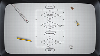
Flow charts
Computer control programmes are written using a series of symbols that are set up in the format of a flow chart. Flowcharts are diagrams of connected shapes, combined to represent instructions to a workflow or process. Different shapes in a flowchart represent different types of operation, and these shapes have the same meaning worldwide.
Flowchart symbols
Simple flowchart

Flowchart with a decision

carrers
Careers that use design and technology
Jobs that use Design and Technology
A career in Technology and Design often involves developing creative, solutions to existing problems. This may mean anything from designing video games to creating indoor living spaces. As technology advances, the range of careers in design and technology will also expand.
Choosing a career in the Technology and Design sector is appealing for many as it allows individuals to find a rewarding career with room for creativity and innovation.
03:08
Video Transcript
My role is constantly evolving, it is never stagnant, you never sit doing the same thing day in and day out.
— Dominic Devlin - Design Engineer
My first experience of using CAD was in Technology and Design and now I use it every single day in my work.
— Adam O’Rourke - CAD Engineer
Here are just a few jobs that make use of skills found in design and technology
• Interior Designer | • Design Engineer |
• Product Designer | • CAD engineer |
• Video Game Design | • Electrical Engineer |
• Civil Engineer | • Sound Engineer |
• Mechanical Engineer | • Architect |
• Robotics Engineer | • Steel Fabricator |
• Aeronautical engineer | • Electrician |
• Joiner | • Surveyor |
Jobs that use Design and Technology. collectionJobs that use Design and Technology
Where could your favourite subject take you? Get inspired by people using Design and Technology in real-life jobs. Find out how much you could get paid for different roles and what qualifications you might need.
How to become a prop maker: Miles' story
Meet Miles and find out about his role as a prop maker for TV, film and theatre shows.

Sophie's an apprentice plumber for a plumbing company in Surrey.

Reid: apprentice joiner. videoReid: apprentice joiner
Reid is an apprentice joiner on the Queen's Balmoral estate.

Hannah: architectural assistant
Hannah's an architectural assistant who designs and draws up buildings for private clients.

Rhianne: games designer. videoRhianne: games designer
Rhianne designs and tests video games.

Sophie: wardrobe technician. videoSophie: wardrobe technician
Sophie is a wardrobe technician at the Royal Opera House.

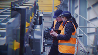
What is engineering?
Engineering is all about problem solving. Engineers use science, maths (and a lot of creative thinking!) to design, test and create machines, structures and processes. They come up with innovative solutions to issues, helping to tackle some of the world's greatest challenges, such as climate change, poverty, cyber security problems and ill health.
There are lots of different types of engineering, including civil, mechanical, electrical and chemical. The different areas are interconnected, meaning you could draw on several types of engineering in a role, or work very closely with engineers from other disciplines.
How to become an engineer. documentHow to become an engineer
Lots of information about all the various types of engineering jobs available
How to become an electrical engineer: Ciaran's story
Ciaran provides solutions that make buildings more efficient and eco-friendly.

Zuzanna: apprentice wing designer. videoZuzanna: apprentice wing designer
Zuzanna's an apprentice wing designer, gaining a degree as part of her apprenticeship.

Sally: civil engineer technician
Sally works on a construction site at Manchester Airport.
Lawrence is a freelance naval architect in Bristol.

Further careers advice
Tips and advice. collectionTips and advice
Help with interviews, writing a CV and all things work experience related.

How to become an engineer. collectionHow to become an engineer
Find out more about the engineering sector and how those currently working in it got their foot in the door.
Careers A to Z: Find your perfect job. listCareers A to Z: Find your perfect job
From actor to zoologist, find the right path for you.