Discreet Math - Chapter 2.4 - " Application: Digital Logic Circuits "
 Call Kai
 Learn
Learn Practice Test
 Spaced Repetition
 Match
Match Flashcards
 Knowt Play
1/21

Earn XP
Description and Tags
Vocabulary flashcards covering key concepts, figures, definitions, and logic gate rules from Chapter 2.4: Digital Logic Circuits.
Name | Mastery | Learn | Test | Matching | Spaced | Call with Kai | Chat |
|---|
No analytics yet
Send a link to your students to track their progress
22 Terms

Claude Shannon
An M.I.T. graduate student who in the late 1930s noticed an analogy between switching circuits and logical connectives, publishing his findings in a landmark 1938 master's thesis.

Switches in Series
A circuit configuration where current flows and the light bulb turns on if, and only if, both switches P and Q are closed, corresponding to the logical expression P∧Q.
Switches in Parallel
A circuit configuration where current flows and the light bulb turns on if, and only if, at least one of the switches P or Q is closed, corresponding to the logical expression P∨Q.
Digital Logic Circuits
The basic electronic components of a digital system that process discrete signals using principles of logic.

Bit
Short for binary digit, referring to the symbols 0 and 1 used to denote false and true signal values in digital circuits; terminology introduced in 1946 by statistician John Tukey.

Intel 4004
The first commercially viable microprocessor introduced in 1971, contained on a fingernail-sized chip with 2,300 transistors that executed 70,000 instructions per second.

Black Box
An abstraction of a circuit where the internal physical implementation is ignored, and attention is focused strictly on the relationship between input and output signals.

Input/Output Table
A table that completely specifies the operation of a black box circuit by listing all possible input signal combinations alongside their corresponding output signals.
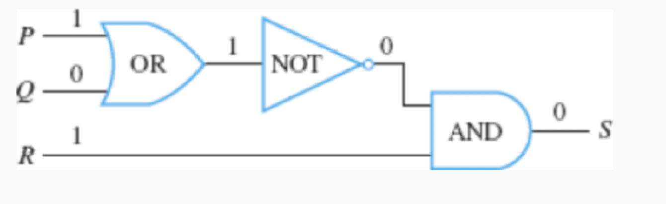
NOT-gate
A digital logic gate (also called an inverter) with one input signal and one output signal that converts an input of 1 to 0 and an input of 0 to 1.
AND-gate
A digital logic gate with two input signals and one output signal that produces an output of 1 if and only if both input signals are 1; otherwise, it outputs 0.
OR-gate
A digital logic gate with two input signals and one output signal that produces an output of 0 if and only if both input signals are 0; otherwise, it outputs 1.
Combinational Circuit
A digital logic circuit whose output at any time is determined entirely by its input signals at that time, obeying rules that prohibit feedback loops and wire combinations.
Sequential Circuit
A complex circuit whose output at any given time depends both on the input signals at that time and on previous inputs, achieved by feeding a gate's output back into itself.

Boolean Variable
A variable (such as a statement variable or input signal) that can take one of only two values, typically denoted as 1 or 0 (or T or F), named in honor of George Boole.
Boolean Expression
An expression composed of Boolean variables and logical connectives such as ∧, ∨, and ∼.
Recognizer
A logic circuit designed to output a 1 for exactly one specific combination of input signals and 0's for all other input combinations.
Disjunctive Normal Form
A Boolean expression structured as a disjunction (OR) of terms that are themselves conjunctions (ANDs) containing each input variable or its negation; also called sum-of-products form.
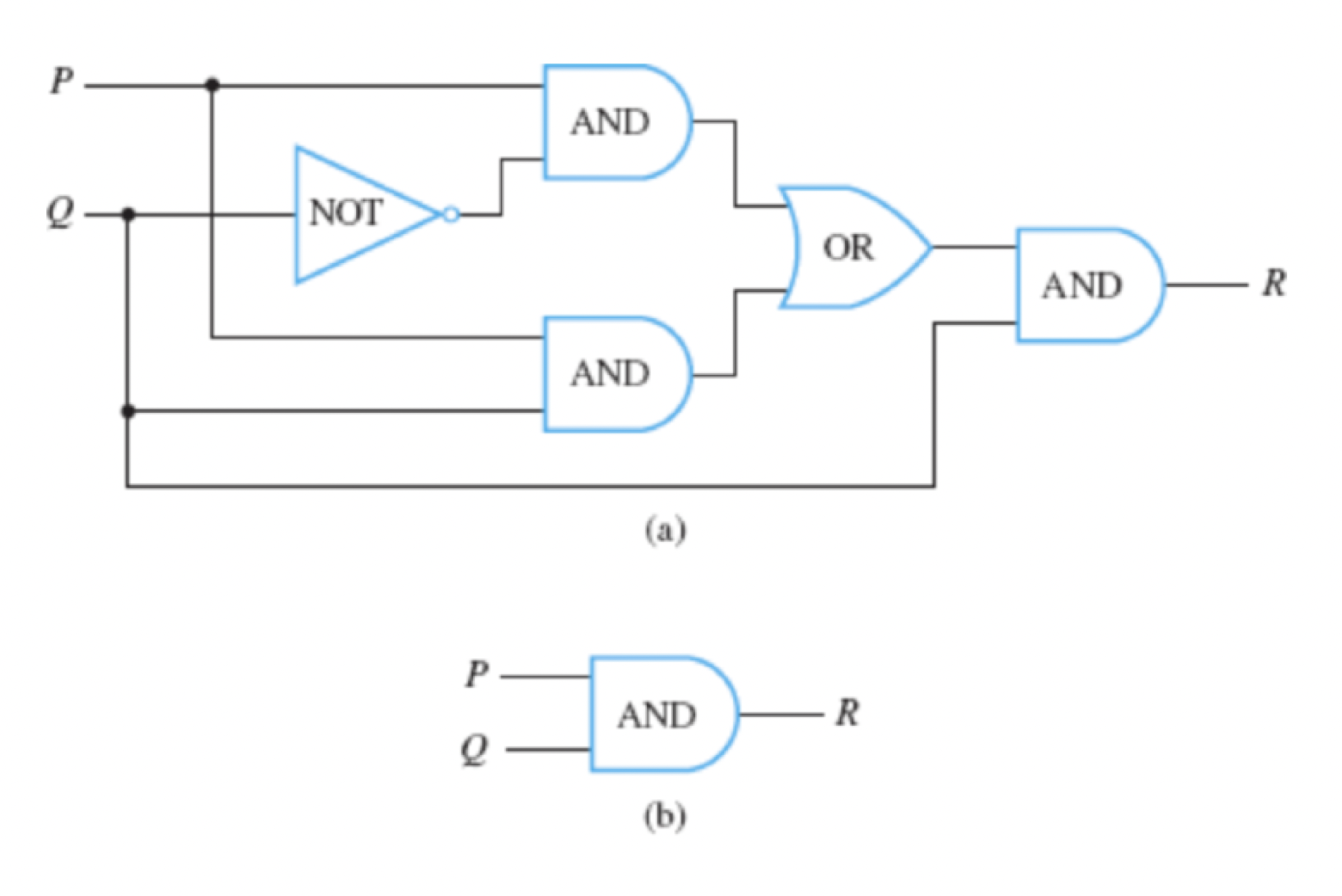
Equivalent Digital Logic Circuits
Two or more digital logic circuits that produce identical output signals for every combination of input signals, meaning their input/output tables are identical.

NAND-gate
A logic gate that functions as an AND-gate followed by a NOT-gate, outputting 0 if and only if both input signals are 1.

NOR-gate
A logic gate that functions as an OR-gate followed by a NOT-gate, outputting 1 if and only if both input signals are 0.

Sheffer Stroke
The logical operator ∣ (where P∣Q≡∼(P∧Q)) corresponding to the NAND operation, named after H. M. Sheffer.
Peirce Arrow
The logical operator ↓ (where P↓Q≡∼(P∨Q)) corresponding to the NOR operation, named after C. S. Peirce.