Sono Physics Ch. 6 - 7 (Continued)
 Call Kai
 Learn
Learn Practice Test
 Spaced Repetition
 Match
Match Flashcards
 Knowt Play
1/32

There's no tags or description
Looks like no tags are added yet.
Name | Mastery | Learn | Test | Matching | Spaced | Call with Kai | Chat |
|---|
No analytics yet
Send a link to your students to track their progress
33 Terms
Incidence
The angle at which sound strikes a boundary.
Types of Incidence:
Normal and Oblique Incidence
The Angles of Incidence helps Determine:
◦ Reflection
◦ Refraction
◦ Transmission
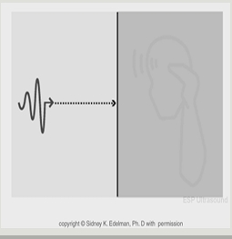
Normal Incidence
Occurs when a sound beam strikes a boundary at exactly 90°
◦ Beam is perpendicular to interface
◦ Angle must be 90°
◦ Reflection is greatest when incidence is normal
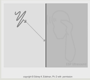
Oblique Incidence
Occurs when a sound beam strikes a boundary at any angle other than 90°
Characteristics:
◦ Angle of incidence is not 90°
◦ May be an acute angle (< 90°)
◦ May be an obtuse angle (> 90°)
Law of Reflection
When reflection occurs:
◦ Angle of Reflection = Angle of Incidence

Reflection depends on what?
Impedance Difference
Reflection at Normal Incidence
Greater impedance mismatch = Greater reflection
Incident Intensity (Total amount of energy before it hits Boundary)
Sound arriving at boundary.
Reflected Intensity (Total that returns to transducer)
Portion that returns toward transducer.
Transmitted Intensity (The portion that continues on into the Medium)
Portion that continues into next medium.
Incident Intensity Formula
Reflected Intensity + Transmitted Intensity
Intensity Reflection Coefficient (IRC)
Percentage of incident intensity that is reflected.
◦ Represents amount of sound energy that returns to transducer
Units: None
Intensity Transmission Coefficient (ITC)
Percentage of incident intensity that is transmitted
◦ Represents amount of sound energy that continues deeper into body
Units: None
Typical Values
◦ IRC & ITC range from 0% to 100%
or 0 – 1.0
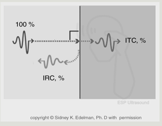
Intensity Coefficients
100% = IRC + ITC
Because energy is conserved, all of the incident intensity must either:
◦ Be reflected
◦ Be transmitted
Intensities = W/cm²
Coefficients = %
Reflection with Normal Incidence
Reflection Depends on Impedance Differences
-Reflection occurs when sound crosses a boundary between tissues with different acoustic impedances.
Intensity Reflection Coefficient (IRC)
◦ Measures the percentage of incident intensity that is reflected at a boundary
IRC (%) = Z2 - Z1 X 100
Z2 + Z1
Reflection w/ Normal Incidence Key Concepts
Key Concepts:
◦ Greater impedance mismatch → More reflection
◦ Similar impedances → Less reflection
◦ Equal impedances → No reflection
Transmission w/ Normal Incidence
Transmission Depends on Reflection
When sound reaches a boundary:
◦ Some intensity may be reflected
◦ The remaining intensity is transmitted
Complete Transmission:
If two media have the same acoustic impedance:
◦ No reflection occurs
◦ 100% of the sound is transmitted
Transmission w/ Normal Incidence
Intensity Transmission Coefficient (ITC)
Measures the % of incident intensity that is transmitted across a boundary
ITC (%) = T𝑟𝑎𝑛𝑠𝑚𝑖𝑡𝑡𝑒𝑑 𝐼𝑛𝑡𝑒𝑛𝑠𝑖𝑡𝑦 / 𝐼𝑛𝑐𝑖𝑑𝑒𝑛𝑡 𝐼𝑛𝑡𝑒𝑛𝑠𝑖𝑡𝑦 X 100
Oblique Incidence: Different Rules Apply
When the sound beam strikes a boundary at an angle (≠ 90°)
◦ Reflection may occur
◦ Transmission may occur
◦ Refraction may occur
◦ Impedance differences alone no longer predict what happens
New Factors Matter:
◦ Angle of incidence
◦ Propagation speed of each medium
◦ Acoustic impedance
Even with Oblique Incidence, Two Rules Never Change
1. Conservation of Energy
All of the incident sound must either:
◦ Be reflected
◦ Be transmitted ◦
100% = IRC + ITC
◦ Incident Intensity = Reflected Intensity + Transmitted Intensity
◦ Intensity has units of W/cm2
2. Law of Reflection
◦ Angle of Reflection = Angle of Incidence
◦ The reflected beam always leaves the boundary at the same angle it arrived
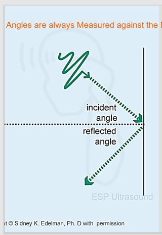
Reflection w/ Obliques Incidence
Law of Reflection:
◦Angle of Reflection = Angle of Incidence
Angle of Incidence
◦Angle between the incident beam and the normal line
Angle of Reflection
◦Angle between the reflected beam and the normal line
Reflection w/ Oblique Incidence Key Points
◦Reflected beam does not always return to transducer w/oblique incidence.
◦Reflected beam leaves boundary at same angle it arrived
◦Angles are measured from normal line
◦ (perpendicular to the boundary)
Refraction
Refraction = Transmission with a bend
◦ The transmitted beam changes direction as it enters a new medium
◦ The reflected beam does not refract.
Refraction ONLY Occurs When BOTH Conditions Are Present
◦ Oblique incidence (angle ≠ 90°)
◦ Different propagation speeds in the two media
No Refraction If:
✘ Normal incidence
✘ Same propagation speeds
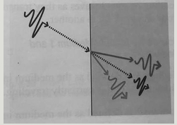
Refraction - Snell’s Law
Snell's Law describes the physics of refraction
Mathematical Description of Refraction:
𝒔𝒊𝒏 ( transmission) = Speed of Medium 2
sin (Incident angle) Speed of Medium 1

Using Snell’s Law
If Medium 2 is Faster
◦ Refracted angle > Incident angle
◦ Beam bends away from the normal
If Medium 2 is Slower:
◦ Refracted angle < Incident angle
◦ Beam bends toward the normal
Time of Flight
Time needed for a pulse to travel to the reflector and back
Also called:
✓Go-return time
✓Round trip time
Ultrasound systems assume sound travels through soft tissue at 1.54 mm/μs
Key Relationship
✓ Time of Flight is directly related to reflector depth
Time of Flight Relationship with Reflected Depth is what?
Directly Related
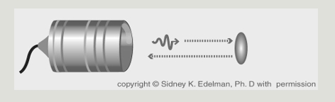
Time Of Flight Equation
Depth (mm) = 𝟏.𝟓𝟒 𝒎𝒎 / µ𝐬 × 𝒈𝒐 𝒓ⅇ𝒕𝒖𝒓𝒏 𝒕𝒊𝒎𝒆 (µ𝒔) / 2
Why divide by 2?
The pulse travels:
-To the reflector
-Back to the transducer
The measured time includes both directions, so divide by 2 to find reflector depth
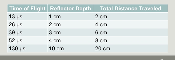
The 13 - Microsecond Rule
Always applies when sound travels through soft tissue
Every 13 μs of go-return time corresponds to 1 cm of reflector depth
From Time of Flight to PRP
Before another pulse can be sent
The system must wait for the first pulse to:
✓ Reach the deepest reflector
✓ Return to the transducer
This waiting time is called Pulse Repetition Period (PRP)
Pulse Repetition Period (PRP)
PRP is time from beginning of one pulse to beginning of next pulse
Think of PRP as the machine’s listening time:
◦ Send a pulse
◦ Listen for all echoes to return
◦ Sent the next pulse
PRP Relationship to Imaging Depth is what?
Directly Related
Shallow image → Short PRP
Deep image → Long PRP
PRP (µs) = Imaging depth (cm) x 13 µs / cm
Pulse Repetition Frequency (PRF)
PRF is the number of pulses the transducer sends each second
Units = Hz
Key Relationship:
✓ PRF is inversely related to imaging depth
Shallow image → High PRF
Deep image → Low PRF
PRF Equation
PRF (Hz) = 𝟕7,𝟎𝟎𝟎 𝒄𝒎/𝒔
𝒊𝒎𝒂𝒈𝒊𝒏𝒈 𝒅𝒆𝒑𝒕𝒉