Statics Concepts
 Call Kai
 Learn
Learn Practice Test
 Spaced Repetition
 Match
Match Flashcards
 Knowt Play
1/71

There's no tags or description
Looks like no tags are added yet.
Name | Mastery | Learn | Test | Matching | Spaced | Call with Kai | Chat |
|---|
No analytics yet
Send a link to your students to track their progress
72 Terms
Force Classifications
Contact (push/pull)
Body (gravitation, magnetic)
Force Application
Concentrated
Distributed
Force Location
External - change motion or develop reactions
Internal - cause deformations
Force Characteristics
Magnitude + Direction + Point of Application + Unit
Transmissibility
Either force has the same external effect
Force Systems
Concurrent - LOAs intersect at a point —> can replace with on force (Fr = F1 + F2 + F3)
Non-concurrent: LOAs don’t intersect
Mo in scalar and vector notation
Scalar: Mo = Fd
Vector: Mo = r x F
Varignon’s Theorem
The forces along a same LOA create the same moment
Characteristics of a Moment of a Couple
Equal magnitude
Opposite direction
Parallel LOAs
Non-collinear
Newton’s First Law
An object remains at rest if there is no unbalanced force acting on it
Equations of Equilibrium (Concurrent)
ΣFx = 0
ΣFy = 0
Equations of Equilibrium (Non-concurrent)
ΣFx = 0
ΣFy = 0
ΣMAny Point = 0
Required Items of a Free Body Diagram
Body detached from its surroundings
Coordinate axis system
Reactions & applied forces
Dimensions and member labels
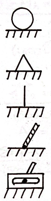
Support Conditions
Roller (positive-y)
Pin (positive-y and positive-x)
Fixed (positive-x, positive-y, and positive-z)
Cable (tension)
Frictionless Slot (positive-y)
Fr (in terms of a resulting force in centroid problems)
Equivalent concentrated force/area under the load curve
Centroid
Geometric center of a line, area, or volume
Conditions of a centroid
Same as center of mass/gravity for homogenous material
Not necessarily on the shape
Always located on the axis/axes of symmetry
Fluid Pressure
p = ρgh *valid only for incompressible fluids
Two-Force Members
Member with forces applied only at its ends
Characteristics of Two-Force Members
Neglect self-weight
No applied moments or couples
Frictionless pins at the ends
Positive = tension; Negative = compression
The forces are
Equal
Opposite
Collinear (same LOA)
Truss
structure composed of two-force members joined at their ends by frictionless pins (basically interlocking triangles)
Where and Why Trusses?
Where: bridges, roofs, cranes
Why: efficient, long-span, beautiful
Assumptions of trusses
Members connected at the ends only
Loads are applied only to truss joints
Self-weight neglected or placed at joints
Truss cutting procedure
ID members of interest
Solve external forces, if necessary
ID zero-force members
Cut truss - joint/section method
Solve for internal forces
Truss cutting rules
Cut members of interest
Don’t cut through joints
Cut through entire truss
# unknowns <= # equations of equilibrium
Assume tension
Zero-Force Member
A member that carries no load
Zero-force members Rules of Thumb (2 Member Joints)
Both members are zero-force members if:
Two non-collinear members form a joint
No external loads or reactions at joint
Members do not have to form a right angle
Zero-force members Rules of Thumb (3 Member Joints)
The non-collinear member is the zero-force member if:
Two collinear and one non-collinear member form a joint
No external loads or reactions at joint
Members do not have to form a right angle
Frame
A structure with at least one multi-force member
Multi-force Member
A member with either
3 or more forces acting on it, not just at its ends
2 or more forces and one or more couples acting on it
Frame & Machine procedure
Solve for external reactions, if necessary
Pull the pins
ID two-force members
ID multi-force members
Apply Newton’s 3rd Law
Include MDP+U & on which member with results
Beams
Members with loads applied perpendicular to the longitudinal axis
Statically Determinate Beam Classifications
Simply supported
Cantilever
Combination
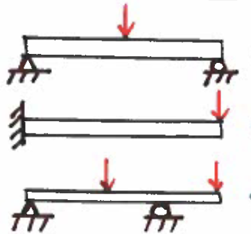
Statically Indeterminate Beam Classifications (# unk > # eq)
Continuous
Propped Cantilever
Fixed-fixed
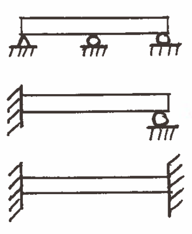
Shear & Moment Diagrams
Graphs which plot internal shear and moment along the length of the member
Plot position on x-axis and plot shear/moment on y-axis
dM/dx = V
Slope of moment curve = magnitude of shear curve at a point
dV/dx = w(x)
Slope of shear curve = magnitude of load curve at a point
M2-M1 = ΔM = ∫Vdx
Change in moment between two points = area under shear curve between two points
V2-V1 = ΔV = ∫w(x)dx
Change in shear between two points = area under load curve between two points
V&M Diagram Tips
Always start and end at zero
Concentrated loads cause jumps in shear diagram (up is +)
Concentrated moments cause jumps in moment diagram (c-clockwise is +); causes no change to V-diagram
At V=0, moment is a local minimum or maximum
Always work V and M diagrams from left to right
Areas
Trapezoid = ½ (a + b) x h
Parabolic = 2/3 (a x b)
Triangle = ½ (b x h)
Sub-parabolic = 1/3 (a x b)
Uses of cables
Suspension bridges
Power transmission lines
Tension only members
Strand in prestressed tension
Benefits of cables
Flexible
Light
Efficient
Cross-section of a cable
Wires around a central core
Typical Configurations of Cables
Parabolic
Catenary
Discrete
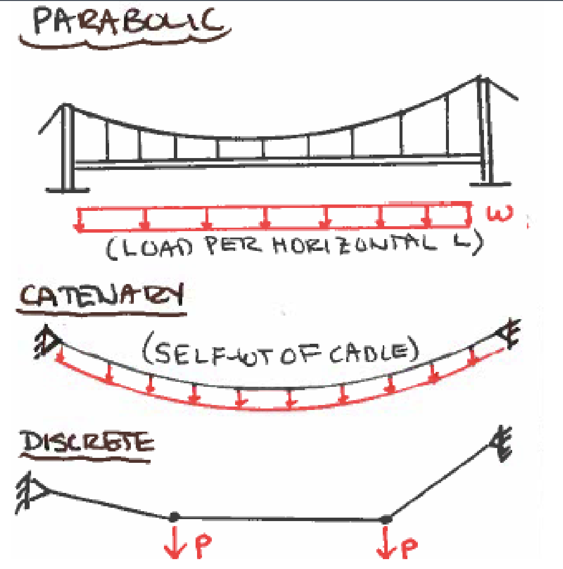
W (cable)
Uniformly distributed load (in weight/length)
To (cable)
Tension force in cable where θ = 0 (base of sag) —> horizontal component
y (cable)
Vertical distance from base of sag to desired height
Catenary Cable
Example: Power lines
At lower sag values, a parabolic approximation is good
Solved with computer analysis
Discrete Cable
Neglect self-weight
Apply equations of equilibrium
Solve like a truss
F (in terms of 3D Force)
Force vector
F (in terms of 3D Force)
Magnitude of the force
l, m, and n (in li+mj+nk)
Portion of direction
n (in terms of 3D Force)
unit vector = (li + mj + nk)
where l2 + m2 + n2 = 1
Right-hand rule (3D Forces)
Arrows indicate (+) direction
Using the right hand, run fingers in (+) x-direction, wrapping them around to the y-direction, and thumb is z-direction
Moment (in 3D)
Mo = r x F
Cross Product
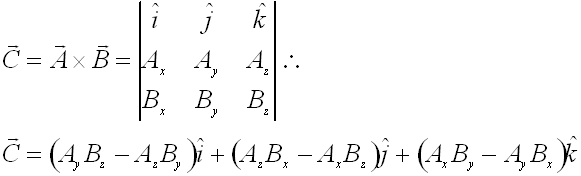
Notes about 3-Dimensional Equilibrium
ΣF = 0 (Fx, Fy, Fz = 0) and ΣM = 0 (Mx, My, Mz = 0)
The equilibrium conditions are independent of one another
All conditions must be met for complete equilibrium
Right-handed coordinate system with vector notation
Complete free-body diagram is very important
Complete Fixity
Body is stable for translation and rotation (ΣF = 0, ΣM = 0)
Incomplete Fixity
Body is not stable in all directions for translation and rotation
Excessive Fixity
Body has redundant reactions
Notes About Statical Determinancy
If > 6 reactions, indeterminate
If < 6 reactions, determinate but unstable
If = 6 reactions, determinate and stable
Types of Friction
Dry friction (coulomb friction): occurs between two unlubricated solid surfaces
Fluid friction: occurs between adjacent layers in a fluid or gas
Internal friction: occurs in all solid materials subjected to cyclic loading
Impending Motion
about to do something; either slip or tip
μs and μk
coefficient of statics/kinetic friction
Belt friction
Belts/cables/ropes wrapped around sheaves, drums, or pulleys
How Belt Friction Works (Types of Cores)
Fixed core: provides frictional resistance to the belt passing around it
Rotating core: offsets the greater tension force, T2
Examples of Pulleys
cranes
elevators
exercise equipment
sailboats
climbing gear
fishing reel
x:1 Mechanical Advantage
x rope(s) “connected” to the weight
must cut x number of ropes for weight to fall (ignore the tension-part rope)
Levers
F•d1 = W•d2
Inclined Plane
F = Wsinθ
Raise weight up with little effort
Assuming low friction (use hand cart)
Rollers
use levers to lift the object to be moved
place rollers (ex. pipes) under the object
move rollers from back to front as object moves