Week 3 Physics
1/40
There's no tags or description
Looks like no tags are added yet.
Name | Mastery | Learn | Test | Matching | Spaced | Call with Kai |
|---|
No analytics yet
Send a link to your students to track their progress
41 Terms
Amplitude verse Frequency
Amplitude refers to the maximum displacement of particles in the medium through which the sound wave is traveling, affecting the perceived loudness, while frequency indicates the number of oscillations (vibrations) of the wave per second, measured in Hertz (Hz), which influences the pitch of the sound.
Relationship between Power & Amplitude
Power is directly related to the square of the amplitude; as the amplitude increases, the power transmitted by the sound wave also increases exponentially.
Example of non-linear relationship
Relationship Between Amplitude, Intensity, and Power
Power is proportional to the square of amplitude:
P ower∞Amplitude2
Intensity = Power/Area
Doubling amplitude increases power by a factor of four and intensity by a factor of four also, assuming constant area.

Attenuation in Ultrasound
Loss of sound energy as it travels through tissue
Measured in units of Decibels (dB).
Needs to be compensated by the diagnostic instrument as the sound travel.
exponential and non-linear
Factors influencing attenuation
Tissue type (density and composition)
Frequency of the ultrasound (higher frequencies attenuate more).
Types of attenuation
Absorption, reflection, scattering and refraction
Absorption
Refers to the conversion of sound energy into other forms of energy, often thermal.
Tissue types absorb differently: fat, muscle, and bone exhibit varying absorption rates.
Reflection
Sound bouncing off a boundary between two different media
Occurs at an interface between 2 dissimilar mediums
Each has an acoustic impedance value (Z values)
Scattering
Dispersal of sound energy in various directions, important for imaging
Refraction
Bending of sound waves when entering different mediums i.e. change in direction of sound when it crosses a boundary, leading to artifacts in imaging such as lateral position artifact and edge shadowing
Time gain compensation and attenuation
Without time gain compensation, tissue attenuation causes gradual loss of display of deeper tissues
By applying increasing amplification or gain to the backscattered signal to compensate for this attenuation a uniform echo return can be generated, allowing for a clearer image of the deeper tissues that may otherwise be obscured by the effects of sound wave scattering and absorption.
Factors affecting attenuation:
Frequency of the sound beam.
Type of medium through which sound is traveling.
Distance the sound has traveled.
Attenuation coefficient
Attenuation = a x f (MHz) x L (cm)
Depth and Attenuation
As imaging depth increases:
The length path of the ultrasound pulse increases, thereby increasing attenuation.
For soft tissue, there is an increase in attenuation of 0.5 dB/cm for every MHz of frequency used.
Reflection and Transmission
The extent of sound energy reflection depends on the difference in acoustic impedance between two adjacent media:
Large difference in = significant reflection of energy.
If Z2 >> Z1, near-complete reflection occurs.
Minor differences allow for continued sound propagation
Percent Reflection and Transmission
% Reflection and % transmission at a boundary interface can be measured
Total reflection and transmission at an interface equals 100%:This means that
the sum of the percent reflection and percent transmission must always add up
to 100%, indicating that all incident acoustic
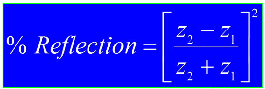
The brightness of structures on ultrasound images depends on reflection strength
Larger acoustic impedance differences result in hyper-echoic interfaces (bright images).
Smaller differences in result in less echogenic interfaces (dimmer images).
Anechoic structures (e.g., fluid-filled areas) present no reflection when Z1 = Z2
Small differences in Z = homogenous
Larger differences in Z = heterogenous
Importance of Ultrasound Gel
Significant acoustic impedance mismatch in air and soft tissue
Minimize the reflection of ultrasound waves at the transducer/air interface to improve transmission through the body.
Reflection at the metal/air interface is significant (>99.998%); coupling with gel ensures effective sound transmission into the body.
Reflection types
Specular Reflection
Diffuse Reflection
Scattering
Wave Interference
Rayleigh Scattering
Specular Reflection
Mirror-like reflections from large, smooth, and flat structures.
Specular Reflection Characteristics
Produces bright echoes, especially at perpendicular incidence
Frequency independent
Highly angle dependent
Diffuse reflection characteristics
Occurs from rough surfaces
Reflects sound in many directions
Typically has a low echo amplitude
Diffuse vs specular reflection
Specular: one direction, strong echoes
Diffuse: many directions, weaker echoes
Scattering
Occurs when the surface of a reflector is rough and similar or smaller in comparison to the sound wavelength.
Scattering characteristics
Angle independent
Produces low echo amplitude
Contributes to the echotexture of organs
More common than specular reflections
Frequency dependent
Creates a speckle pattern referred to as "tissue textur
Speckle
Form of acoustic noise resulting from interference of echoes
Types of Interference
Constructive Interference:
Occurs when two similar waves arrive nearly simultaneously, resulting in a higher amplitude echo.
Destructive Interference:
Two similar echoes with different arrival times cancel each other, resulting in a lower or nearly zero amplitude echo.
Speckle effects on images
Contribute to image texture and noise in ultrasound imaging
Rayleigh Scattering
Refers to scattering that occurs when reflecting structures are very small relative to the wavelength.
Rayleigh Scattering characteristics
Often occurs with red blood cells (RBCs) because the diameter of RBCs are small in comparison to the wavelength of diagnostic ultrasound
Scatter is more significant with higher frequencies (degree of Rayleigh scattering α f4 )
Angle independent but frequency dependent
Rouleaux
Clumping of RBCs occurs at slow speeds
Clumps producer stronger reflections compared to individual RBCs
Echo strength varies based on
Change in acoustic impedance (Z)
Size of the reflector
Smoothness of the reflector
Interference type
Important parameters for refraction
Incident Wave: The wave coming toward the boundary.
Reflected Wave: The wave that bounces back from the boundary.
Transmitted Wave: The wave that continues into the second medium
Oblique Incidence
Direction of travel of the incident sound wave is not perpendicular to the interface of two media.
Undesirable effects may occur where reflected sound travels off in a different direction.
Snell’s Law
Governing principle that describes refraction.
It determines how much the wave bends based on the angle of incidence and speeds in the two media.
Conditions for refraction
1. The angle of incidence is oblique (i.e., not perpendicular).
2. There must be differing propagation speeds in each medium
Types of Artifacts from Refraction
Lateral Position Artifact:
Incorrect positioning of structures due to bending of sound waves.
Edge Shadowing:
Shadowing effects at the edges of structures due to refraction.
Double Aorta Artifact:
Misinterpretation of anatomy resulting from sound waves bending at oblique
angles.
Factors Influencing Refraction
Angle of Incidence: Transition from 0° (perpendicular) to critical angles.
Speed of Sound: Different propagation speeds lead to different bending outcomes:
Slower medium: Sound refracts towards the vertical.
Faster medium: Sound refracts away from the vertical.
Critical Angle and No Refraction
If the angle of incidence exceeds the critical angle, refraction cannot occur, and reflection is the only outcome.
Conditions for no refraction:
Beam is perpendicular: .
No change in propagation velocity between the media: Ci = Ct.
Distance Determination Process
1. Time Tracking: The ultrasound system tracks echo return time.
2. Range Equation:
Distance = Time x Velocity
Corrected for round-trip time to provide accurate measurements.
Complete Range Equation
Pulse round trip (us) = 2 x Distance (mm) / Propagation speed (mm/us)