RNS(1) - Normal Residual Heat Removal
1/31
There's no tags or description
Looks like no tags are added yet.
Name | Mastery | Learn | Test | Matching | Spaced |
|---|
No study sessions yet.
32 Terms
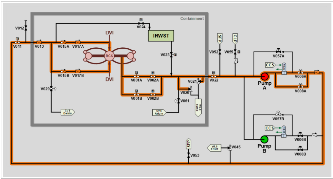
Simplified Diagram
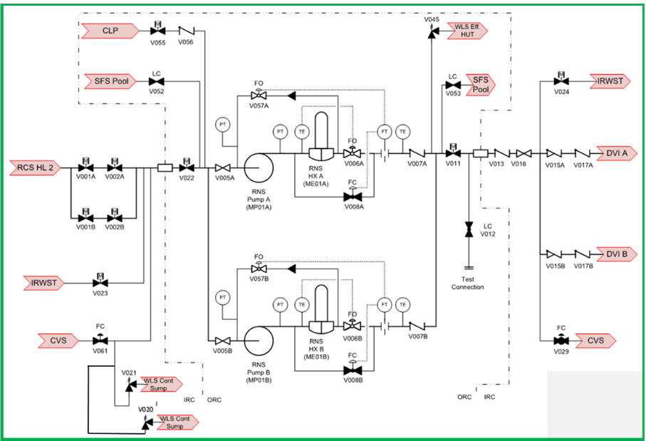
RNS
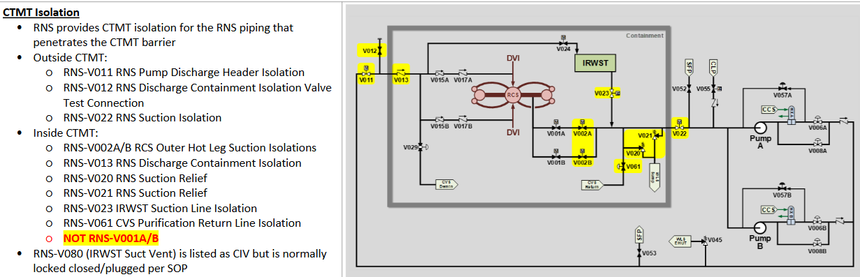
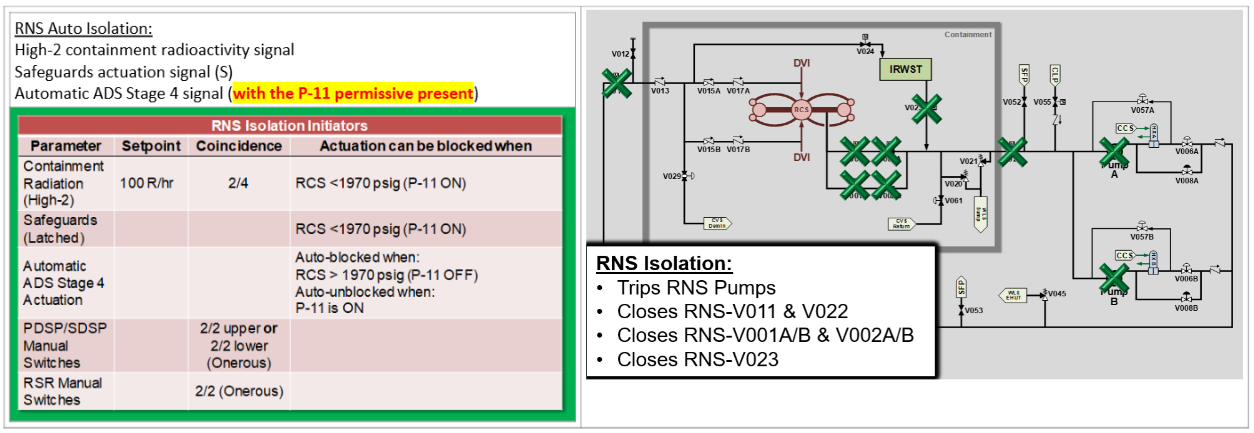
Containment Isolation
This is not a “T” signal, this is an RNS Onerous isolation
V061 CVS Purification Return Line is the only “T” valve
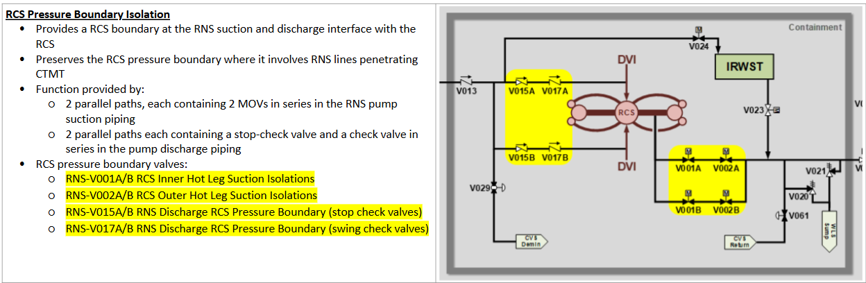
RNS
Pressure Boundary Isolations
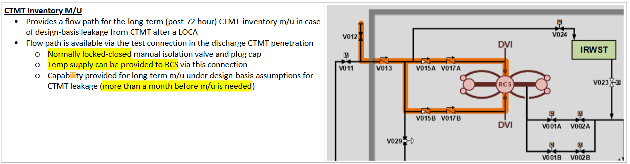
RNS
Containment Inventory MU
RNS
Normal SDC Operations
Turbine Bypass valves will cooldown to <350F and <400psig*
RNS cools down to <125F within 96hrs
Once <130F RNS can be aligned to purification
*During Purification flow CVS makeup is NOT available to RCS
*E-Network Limitations: 400F and 417psig
RNS
Cooldown Limitations
LTOP
When on RNS the RCS is normally <350F
Below 350F, the cooldown limit is 50F/hr
RNS-V020/V021 Lift at 470/500psig respectively and discharge to Containment Sump
*V020: 1”(50gpm) V021: 3”(850gpm)
RNS Purification
Temperature Limitation?
Flow?
RNS-V029 isolates if CVS-T002 >135.5F
<40gpm
3.4.14 Low Temperature Overpressure Protection (LTOP)
LCO
At least one of the following methods must be Operable WITH Accumulators isolated
BOTH LTOP valves Operable and CVS-091 Closed
RCS Vented >/= 4.15 in²
3.4.14 Low Temperature Overpressure Protection (LTOP)
Applicability
MODE 4 Any Cold Leg </=275F
MODE 5
MODE 6 with Head on
3.4.14 Low Temperature Overpressure Protection (LTOP)
<1hr Action(s)
Accumulator connected when Acc. Pressure > RCS CL:
Isolate Acc. 1hr
CVS-V091 Not Closed:
Close 1hr (Not needed when vented)
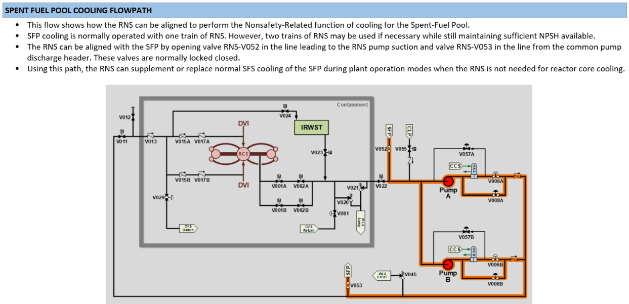
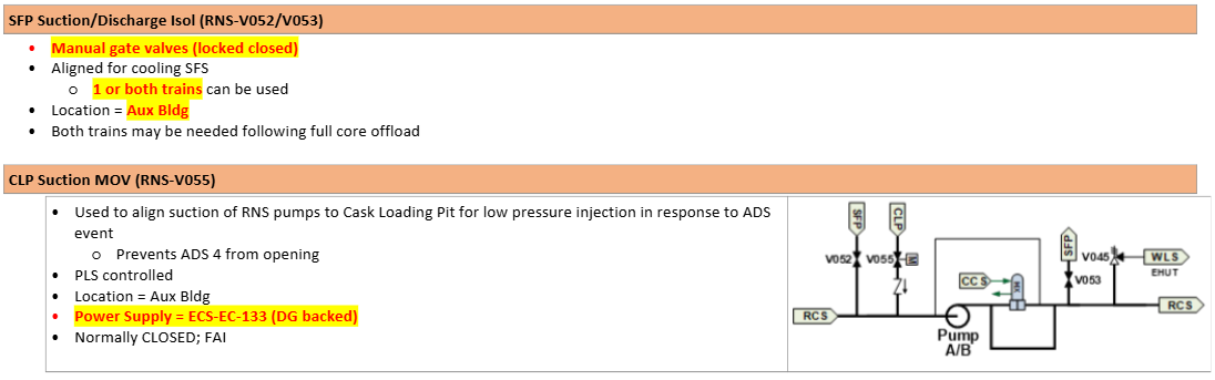
RNS to Spent Fuel Pool
Local Manual Alignment
CAN align both trains to SFP if needed
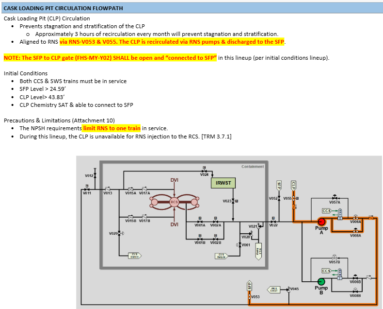
RNS to CLP
Limited to ONE train due to NPSH limitation
Flowpath: From CLP through RNS to SFP
Therefore; CLP and SFP MUST be crosstied (gate open) during performance
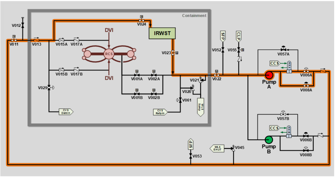
RNS
IRWST Cooling
Can use BOTH trains if desired
RNS
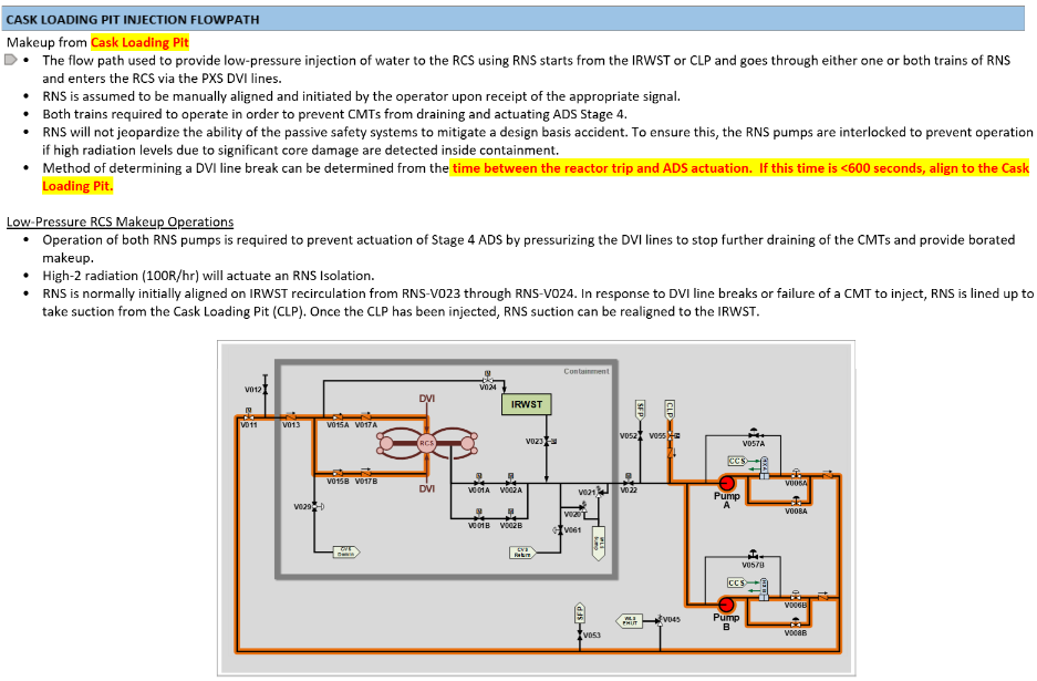
CLP Injection to RCS
RNS
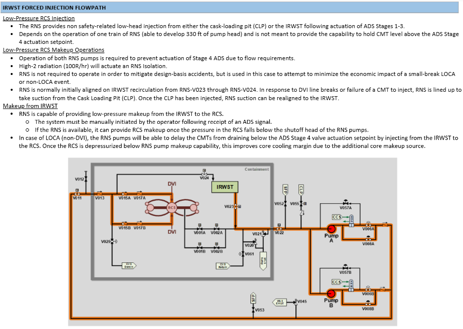
IRWST Forced Injection to RCS
RNS
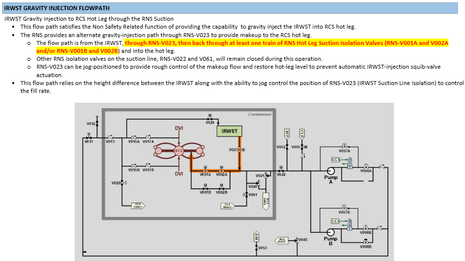
IRWST Gravity Injection to RCS
RNS
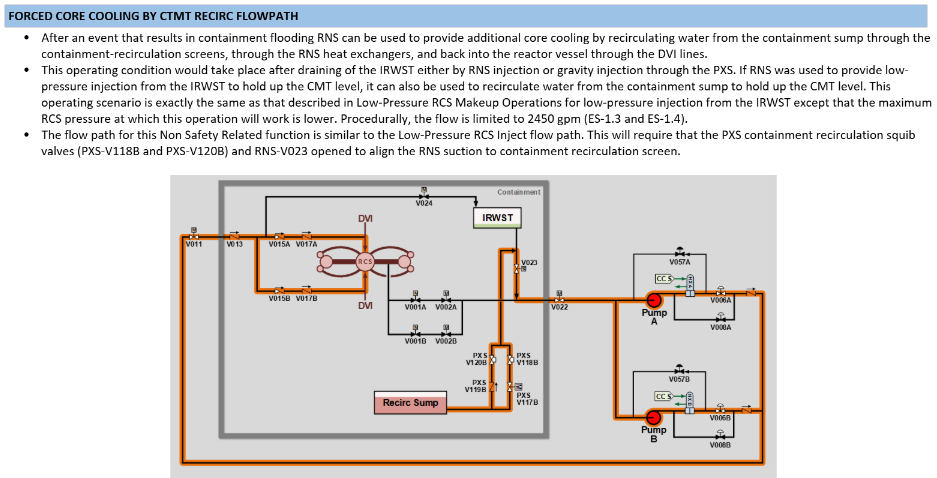
Post Containment Flooding
RNS
Suction Line Isolation
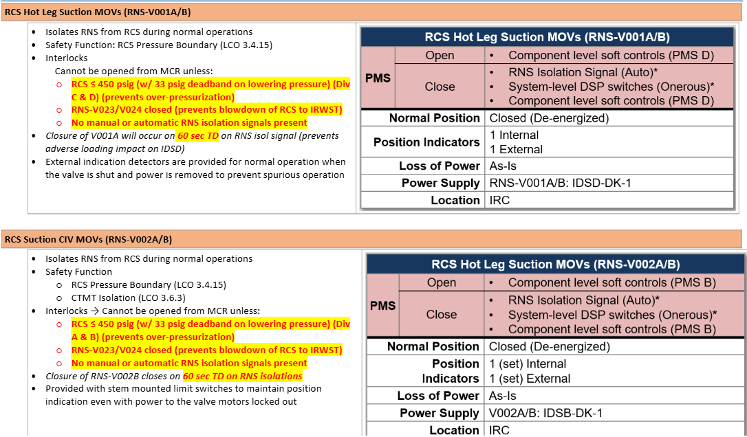
0 sec: 1A & 1B Close
+60sec: 2A & 2B Close
Delay due to IDS loading limitation
RNS
Automatic Isolation
RNS
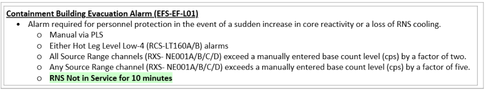
Containment Evacuation Alarm
RNS
Hot Leg Suction Isolations
RNS
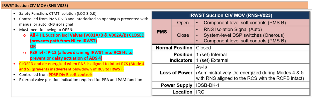
IRWST Suction CIV MOV
(RNS-V023)
RNS
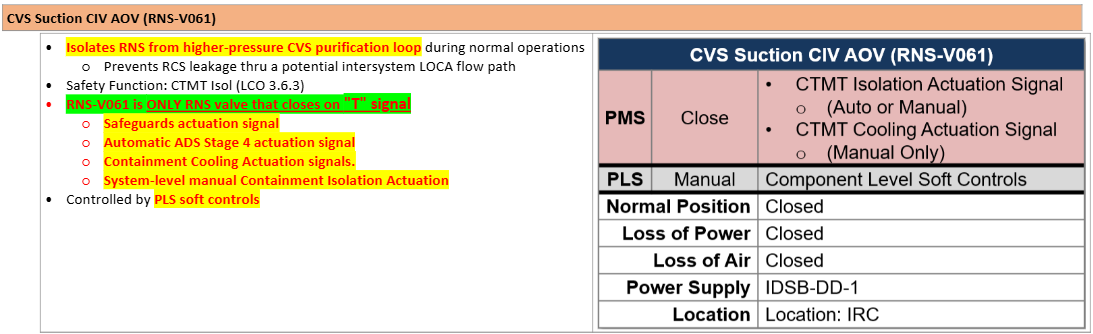
CVS Suction CIV AOV
(RNS-V061)
RNS
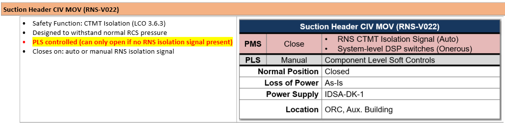
Suction Header CIV MOV
(RNS-V022)
RNS
SFP & CLP Alignment Paths
T 3.7.1 RNS - RCS Makeup
LCO
Applicability
ONE train shall be Functional
MODES 1, 2, and 3
T 3.7.1 RNS - RCS Makeup
TRS
Head on recirc?
Valves stroke open?
330 feet of head
RNS-V011, V022, V023, V055
T 3.7.1 RNS - RCS Makeup
Bases
Makeup (To be Functional): From CLP and IRWST into RCS
“Pressure boundary maintenance cannot be performed when RNS is in SDC, therefore PB maintenance should be done in MODES 1, 2, and 3”
T 3.7.2 RNS - RCS Open
LCO
Applicability
TWO trains shall be Functional AND ONE pump in operation
MODE 5: Open
MODE 6: UppIntern in place
MODE 6: <23’ above flange
T 3.7.2 RNS - RCS Open
TRS
One Pump flow requirement?
Two Pumps flow requirement?
One: >1,580gpm
Two: >2,000gpm
T 3.7.2 RNS - RCS Open
Bases
Standby train requirements?
Neither train Functional limitations?
Planned maintenance?
If standby: Must be available to be placed in service from MCR
Plant should NOT enter RCS-Open if NO train Funcitonal
MODE 1, 2, 3, or 6 >23’ flange
SFP Suction Isolation RNS-V052
Manual Valve, NOT affected by RNS Isolation or any other signal(s)