Reinforced Concrete and Foundation Engineering: Key Concepts and Philippine Terms
1/306
There's no tags or description
Looks like no tags are added yet.
Name | Mastery | Learn | Test | Matching | Spaced | Call with Kai |
|---|
No study sessions yet.
307 Terms
Reinforced Concrete
Concrete in which steel reinforcement is embedded in such a manner that the two materials act together in resisting forces.
Plain Concrete
Concrete having no reinforcement, or reinforced only for drying shrinkage or thermal stresses.
Ferrocement
Constructed of cement-sand mortar over wire mesh that has been preshaped over a mold.
Cast-in-Place Concrete
Concrete which is deposited in the place where it is required to harden as part of the structure, as opposed to precast concrete.
Reinforcement
A system of steel bars, strands or wires for absorbing tensile, shearing and sometimes compressive stresses in a concrete member or structure.
Deformed Bar
A reinforcing bar hot-rolled with surface deformations to develop a greater bond with concrete.
Tension Reinforcement
Reinforcement designed to absorb tensile stresses.
Compression Reinforcement
Reinforcement designed to absorb compressive stresses.
Balanced Section
A concrete section in which the tension reinforcement theoretically reaches its specified yield strength as the concrete in compression reaches its assumed ultimate strain.
Overreinforced Section
A concrete section in which the concrete in compression reaches its assumed ultimate strain before the tension reinforcement reaches its specified yield strength.
Underreinforced Section
A concrete section in which the tension reinforcement reaches its specified yield strength before the concrete in compression reaches its assumed ultimate strain.
Beam
A rigid structural member designed to carry and transfer transverse loads across space to supporting elements.
Simple Beam
Refers to a beam having a single span supported at its end without a restraint at the support.
Semi-continuous Beam
Refers to a beam with two spans with or without restraint at the two extreme ends.
Cantilever Beam
A beam supported on one end and the other end projecting beyond the support, beam or wall.
Continuous Beam
A term applied to a beam that rests on more than two supports.
T beam
Part of the floor and beam unit when poured simultaneously thereby producing a monolithic structure.
Reinforced Concrete Beam
A concrete beam designed to act together with longitudinal and web reinforcement in resisting applied forces.
Effective Depth of Section
The depth of a concrete section measured from the compression face to the centroid of the tension reinforcement.
Bar Spacing
The center-to-center spacing of parallel bars, the resulting clear distance between the bars being regulated by bar diameter, maximum size of coarse aggregate, and thickness of the concrete section.
Span of Supports
Refers to the distances between posts, columns or supporting walls.
Concrete Cover
The amount of concrete required to protect steel reinforcement from fire and corrosion.
Bond
The adhesion between two substances, as concrete and reinforcing bar.
Bond Stress
The adhesive force per unit area of contact between a reinforcing bar and the surrounding concrete.
Development Length
The length of embedded reinforcement required to develop the design strength of reinforcement at a critical section.
Embedment Length
Length of embedded reinforcement provided beyond a critical section.
End Anchorage
Length of reinforcement or mechanical anchor or hook or combination thereof beyond point of zero stress in reinforcement.
Hook
A bend or curve given to the end of a tension bar to develop an equivalent embedment length.
Longitudinal Reinforcement
Reinforcement essentially parallel to the horizontal surface of a slab or to the long axis of a concrete beam or column.
Percentage Reinforcement
The ratio of effective area of reinforcement to effective area of concrete at any section of a reinforced concrete member, expressed as a percentage.
Top Bar
Any of the longitudinal bars serving as tension reinforcement in the section of a concrete beam or slab subject to a negative moment.
Bottom Bar
Any of the longitudinal bars serving as tension reinforcement in the section of a concrete beam or slab subject to a positive moment.
Web Reinforcement
Reinforcement consisting of bent bars or stirrups, placed in a concrete beam to resist diagonal tension.
Bent Bar
A longitudinal bar bent to an angle of 30 or more with the axis of the concrete beam.
Bend Reinforcing Bars
Reinforcing bars that are bent up on or near the inflection point and are extended at the top of the beam across the support.
No Bent Bars
Bars that are not bent, an additional straight reinforcing bars placed on the top of the beam across the supports.
Truss Bar
A longitudinal bar bent up or down at points of moment reversal in a reinforced concrete beam.
Stirrup
Any of the U-shaped or closed-loop bars placed perpendicular to the longitudinal reinforcement of a concrete beam.
Admixtures containing chloride ions
Shall not be used in prestressed concrete containing aluminum embedments if their use will produce deleterious concentration of chloride in the mixing water.
Concrete aggregates specifications
Shall conform to ASTM C 33 or ASTM C 330.
Nominal maximum size of aggregates
Shall not be larger than 1/5 the narrowest dimension between sides of forms, 1/3 the depth of slabs, or 3/4 the maximum clear spacing between individual reinforcing bars.
Water used in mixing concrete
Shall be clean and free from injurious amounts of oils, acids, alkalis, salts, organic materials or other substances that may be deleterious to concrete or reinforcement.
Mixing water for prestressed concrete
Shall not contain deleterious amounts of chloride ions.
Standard Hook
A 90, 135 or 180° bend made at the end of a reinforcing bar according to industry standards.
Standard Hooks specifications
180 bend plus 4db extension, 90° bend plus 12db extension at free end of bar.
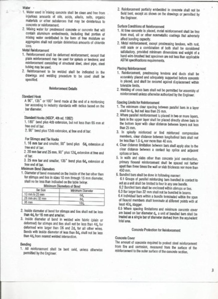
Minimum Bend Diameters for bars
Shall not be less than indicated on the table below: 10 mm to 25 mm - 6d, 28 mm and 32 mm - 8d, 36 mm - 10d.
Bending of reinforcement
All reinforcement shall be bent cold, unless otherwise permitted by the Engineer.
Surface Conditions of Reinforcement
At time concrete is placed, metal reinforcement shall be free from mud, oil or other nonmetallic coatings.
Placing Reinforcement
Shall be accurately placed and adequately supported before concrete is placed.
Spacing Limits for Reinforcement
The minimum clear spacing between parallel bars in a layer shall be d, but not less than 25 mm.
Bundled bars
Groups of parallel reinforcing bars bundled in contact to act as a unit shall be limited to four in any one bundle.
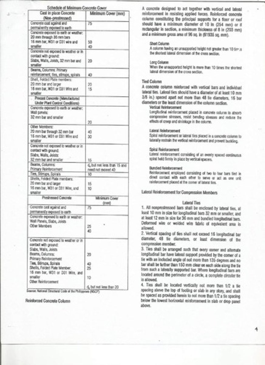
Minimum Concrete Cover for cast in place concrete
75 mm for concrete exposed to earth or weather.
Reinforced Concrete Column
A concrete designed to act together with vertical and lateral reinforcement in resisting applied forces.
Short Column
A column having an unsupported height not greater than 10 times the shortest lateral dimension of the cross section.
Long Column
When the unsupported height is more than 10 times the shortest lateral dimension of the cross section.
Tied Column
A concrete column reinforced with vertical bars and individual lateral ties.
Lateral ties
Should have a diameter of at least 10 mm spaced apart not more than 48 tie diameters, 16 bar diameters or the least dimension of the column section.
Vertical Reinforcement
Longitudinal reinforcement placed in concrete column to absorb compressive stresses, resist bending stresses and reduce the effects of creep and shrinkage in the column.
Lateral Reinforcement
Spiral reinforcement or lateral ties placed in a concrete column to laterally restrain the vertical reinforcement and prevent buckling.
Spiral Reinforcement
Lateral reinforcement consisting of an evenly spaced continuous spiral held firmly in place by vertical spacers.
Bundled Reinforcement
Reinforcement employed consisting of two to four bars tied in direct contact with each other to serve or act as one unit reinforcement placed at the corner of lateral ties.
Lateral Reinforcement for Compression Members
All nonprestressed bars shall be enclosed by lateral ties, at least 10 mm in size for longitudinal bars 32 mm or smaller, and at least 12 mm in size for 36 mm and bundled longitudinal bars.
Minimum covering of ties
Not less than 40 mm and not less than 1.5 times the max. size of coarse aggregate.
Minimum diameter of lateral ties
10 mm diameter.
Lateral ties spacing
Not more than 16 bar diameter, not more than 48 tie diameter, or not more than the least dimension of column.
Clear distance between horizontal bars
Not less than 1.5 times the bar diameter nor less than 1.5 times the max. size of coarse aggregate.
Minimum number of bars
4-16 mm diameter.
Pg
Ratio of gross reinforcement area to gross cross sectional area, ranging from 0.01 to 0.04.
Spiral Column
A concrete column with spiral reinforcement enclosing a circular core reinforced with vertical bars.
Minimum diameter of spiral ties
10 mm diameter.
Spacing of spiral ties
Not more than 75 mm, not less than 25 mm, and not less than 1.5 times the size of coarse aggregate.
Minimum number of bars in Spiral Column
6-16 mm diameter.
Lateral Reinforcement for Compression Members - Spirals
Shall consist of evenly spaced continuous bar or wire of such size and so assembled to permit handling and placing without distortion from designed dimensions.
Anchorage of spiral reinforcement
Shall be provided by 1 1/2 extra turns of spiral bar or wire at each end of a spiral unit.
Composite Column
A type of column where structural steel is embedded into concrete core of a spiral column.
Combined Column
A column with structural steel encased in a concrete of at least 7 cm thick reinforced with wire mesh surrounding the column at a distance of 3 cm inside the outer surface of the concrete covering.
Lally Column
A fabricated post made of steel provided with a plain flat steel bar or plate which holds girder, girt or beam.
Offset Bars
The slope of an inclined portion of an offset bar with axis of column shall not exceed 1 in 6.
Notes on Concrete Columns
Columns shall be of the sizes indicated in the schedule or as detailed in drawings and reinforced as shown, with deformed bars only.
Concrete protective covering
From the face to the reinforcing steel shall be 40 mm.
Splices of vertical bars
Shall be staggered as much as possible, located preferably at the middle half of the column height.
Maximum spacing of lateral ties
Shall be used only outside the heights and away from joints, where a reduced spacing of not more than 0.10 meter on center is required.
Crimping or offsetting the bars
The angle of bend shall not be more than one horizontal to six vertical (1.6).
Extra lateral ties
Shall be provided at the lower end of the bend to care of at least 1.25 of the outside thrust caused by the inclined position of the bar.
Lateral ties and spirals
Shall be provided for the vertical bars of the column within the depth of the beams and/or girders at the intersection with the column and spaced not more than 0.10 meter on centers.
Minimum Thickness of Non-prestressed Beams
The clear distance from the bar to the farther face of the wall shall not be less than 4 bar diameters (4d) if reinforcing bars end in a wall.
Separator for layers of reinforcing bars
Use 25 mm separator at 1 m apart for two or more layers of reinforcing bars, with the bars not bundled.
Beam reinforcing bars supporting slab reinforcement
Shall be 25 mm clear from the bottom of the finish.
Clear concrete covering
Between the face of the beam at the bottom of the sides shall be 350 mm.
Beam bars crossing a girder
Rest beam bars on top of girder bars.
Symmetrical beam reinforcing bars
Shall be symmetrical about the vertical axis whenever possible, and about the center line at midspan except for end spans and where otherwise shown.
Stirrups for rectangular beams
Shall be closed stirrups.
Stirrups for tee beams with flanges on one side only
Shall likewise be closed stirrup.
U stirrups for tee beams with flanges on both sides
May be placed in alternating inverted and upright position.
Live Load
Refers to those movable loads imposed on the floor such as people, furniture and the like.
Dead Load
Refers to the static load such as the weight of the construction materials which generally carry the live load.
Environmental Load
Consist of wind pressure and suction, earthquake load, rainwater on flat roof and forces caused by temperature changes or differentials.
Reinforced Concrete Slab
A rigid planar structure of concrete designed to act together with principal and secondary reinforcements in resisting applied forces.
Principal Reinforcement
Reinforcement designed to absorb the stresses from applied loads and moments.
Shrinkage Reinforcement
Reinforcement placed perpendicular to the principal reinforcement in a one-way slab to absorb the stresses resulting from shrinkage or changes in temperature.