Naval Weapons Exam 1
 Call Kai
 Learn
Learn Practice Test
 Spaced Repetition
 Match
Match Flashcards
 Knowt Play
1/114

There's no tags or description
Looks like no tags are added yet.
Name | Mastery | Learn | Test | Matching | Spaced | Call with Kai | Chat |
|---|
No analytics yet
Send a link to your students to track their progress
115 Terms
weapon
a tool of combat which is ultimately designed with the express purpose of incapacitating personnel and/or destroying equipment
artillery guns
small arms
rocket and missiles
swords/knives
torpedoes
mines
depth changes
ordnance
explosives, projectiles, fuses, propellants, etc. (as opposed to launching and fire control system)
bullet/casing/powder
torpedo as opposed to torpedo tube
rocket
missile
weapons system
a collection of components, both hardware and software, with single or multiple destructive weapons, plus the sensors and operators, which make the entire unit function as designed
person w/ a gun and a round of ammunition that contains gunpowder and a bullet
guns
expanding gases, separate from projectile, provide propulsion
projectile cannot move w/out external force
non-propelled, upguided
once it’s fired, cannot change where it will go
rockets
expanding gases in projectile itself provide propulsion
projectile produces the force needed for it to move
self-propelled, unguided projectile
missiles
guided rocket
expanding gas in projectile itself provides propulsion, but has a known path that is has been intentionally told to travel
path determined by internal and/or external mechanisms
some missiles allow path to be updated mid-flight (like tomahawks) while others do not (trident II D5 missiles)- steering
bombs
dropped ordnance with no self-propulsion
classified by weight
“dumb”/”iron” are unguided
“smart” are guided
torpedo
self-propelled, guided underwater explosive
heavyweight (submarines), lightweight torpedoes (p-8)
mines
self-contained, underwater explosives designed to be placed and remain until contact with an enemy ship
detonation occurs with contact, magnetic field interaction and/or pressure transient
detect to engage sequence
three distinct phases
detection
target detection
localization
classification
tracking
target tracking
engagement
weapon selection
target neutralization
detection
surveillance and detection
search a predetermined area for a target and detect its presence
accomplished actively or passively
actively: sending energy out, waiting for it to bounce off something and return (radar)
passively: receiving energy being emitted by a target (passive sonar)
localizing the target’s position
determine a target’s range, bearing, and depth or elevation
classify the target
estimate the target’s type, number size, identity
tracking
to successfully engage a target, we need continuously updated position and velocity of target (where is it going, how fast)
tracking allows us to:
evaluate how much of a threat the target is
predict target’s future position
determines intercept point for our weapon to ensure weapon is accurately aimed
engagement
effective engagement and neutralization of the target requires that a destructive mechanism be delivered to the target’s vicinity or impact the target
must consider aiming, launch, type of propulsion system of the weapon, and forces subjected to en route
detect
localize
classify
track
weapon selection
neutralize
electromagentic (EM) wave generation
characteristics
transverse
no medium
accelerated charged particles
electric field includes magnetic field
magnetic field induces electric field

two types of waves
mechanical
requires medium for propagation (SONAR)
electromagnetic
requires no medium for propagation
two types of motion
longitudinal
motion of medium moves from left to right
transverse
motion of medium moves up and down
frequency
(f )
rate at which the source oscillates through one complete cycle- cycles per second (Hertz or 1/sec)
wavelength
(λ)
distance between 2 identical points on adjacent waves or distance traveled by wave in one cycle (cm, mm, m)
velocity
( c)
speed that wave travels
c = (λ)(f)
(for EM energy in vacuum, c = 3×10^8 m/s)
amplitude
(a)
maximum displacement of wave from zero (cm, mm, m)
period
(T)
time to complete one cycle (sec)
T = 1/f
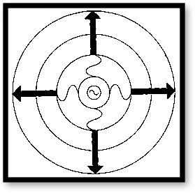
spherical wave (wave propagation)
undisturbed wave
omni directional from source
only works as a model when close to the source
think about ripples on a pong
plane wave (wave propagation)
comes into effect far from the source
spreads out to appear to have same amplitude everywhere on plane perpendicular to direction of travel
think of entire wave traveling in one direction

phase shift (delta phi)
identical sinusoidal waves that’re shifted either ahead or behind due to distance separations or time delay
measured in either degrees or radians
radians = (2pi/360) x degrees
degrees = (360/2pi) x radians
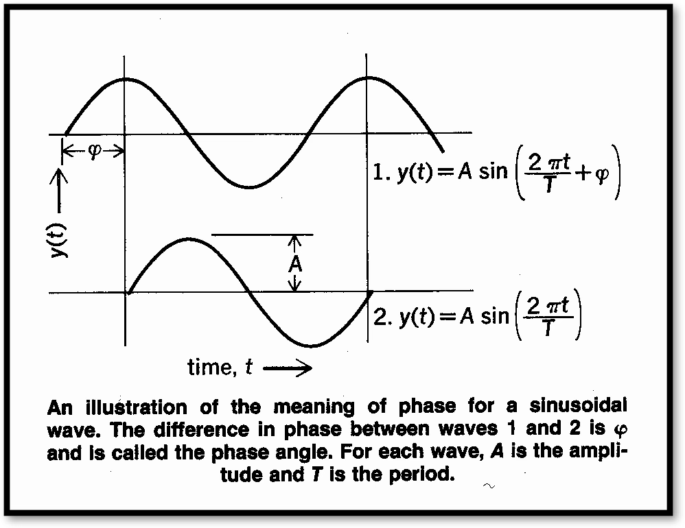
advanced =
positive phase shift
retarded =
negative phase shift
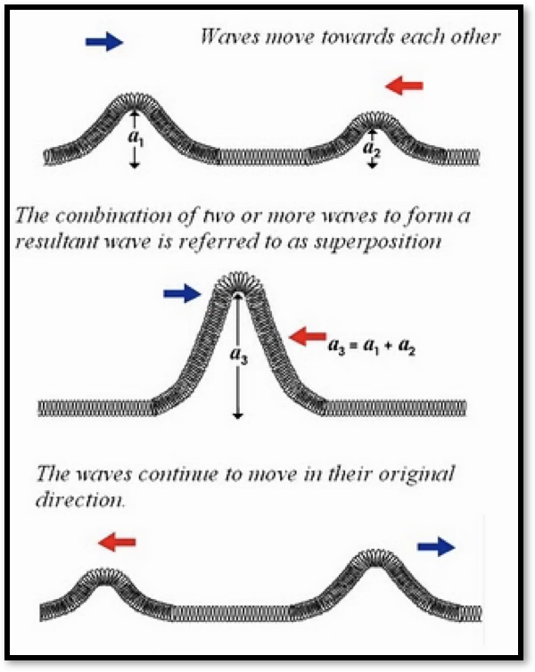
principle of superposition
overlapping waves add algebraically to produce a resultant wave
happens when 2 or more waves pass simultaneously through the same region
reflection
when an electromagnetic wave encounters a conducting surface of energy from that surface occurs
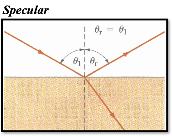
specular reflection
smooth surface reflects at equal but opposite angle
diffuse reflection
irregular surface reflects over a broad range of angles

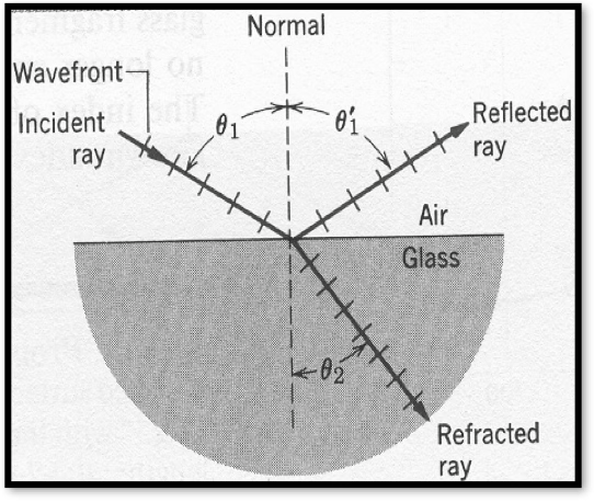
refraction
the bending of an electromagnetic ray when it transmits from one medium to another
when a wave strikes a boundary/surface, not all of wave is reflected
some is transmitted into medium interface at some angle
the angle can be determined using snell’s law
n1 sinθ1 = n2 sinθ2
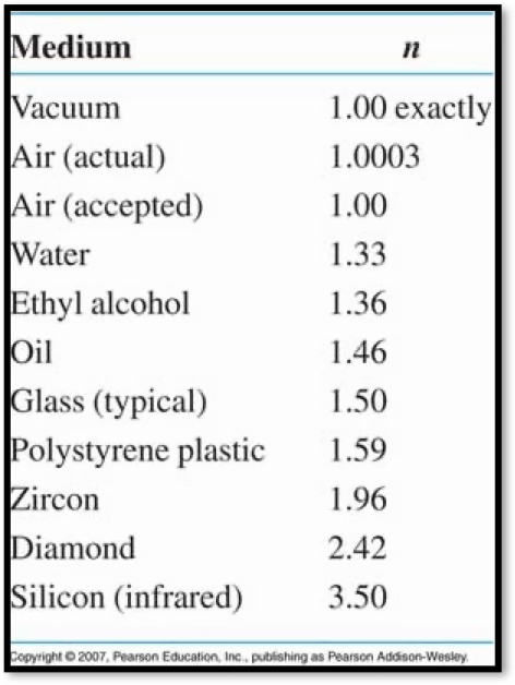
(n = index of refraction for that medium)
refractive index
n = c0 / c
c0 = speed of light (in vacuum)
c = speed of light (in medium)
c = fλ
bend more towards medium with higher index of refraction (waves are lazy)
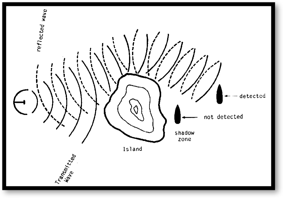
diffraction
causes plane waves traveling in a straight path to bend around a boundary or obstruction
allows radar waves to see “behind” an object like a mountain
also refers to the phenomenon of a wave passing thru an opening (aperture) and spreading out from that opening
amount wave spreads depends on size of the opening
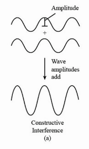
interference
if 2 waves with same frequency are combined, it will cause an interference pattern
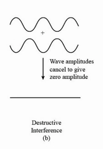
interference can be constructive or destructive
constructive interference
overall field strength has increased (the two wave points get added together)
destructive interference
the overall field strength has decreased (the two wave points get subtracted
electromagnetic signal loss
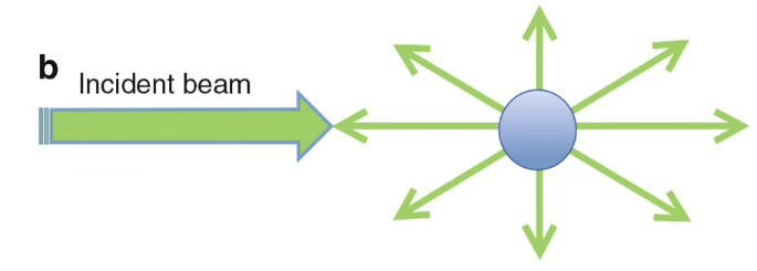
spreading
energy distributed over increasingly larger area (energy) at a point has to go down as the area increases
scattering
energy bouncing off suspended particles within a medium
absorption
energy dissipated into medium (molecules of medium absorb some of the energy as it passes thru)
scattering and absorption both cause attenuation (loss) of energy
modes of propagation
ground waves (<30kHz)
vertically polarized waves, travel between ground and ionosphere
very long range is possuble
ELF, VLF, LF, can be MF
sky waves (30kHz-30MHz)
waves refracted back to the earth by inososphere
changes btwn night/day due to atmospheric conditions
travel far due to refraction and relfection
MF, HF, can be LF
space waves (>30MHz)
signal frequency is too high to be refracted by ionosphere
short range comms
VHF, UHF, SHF, EHF
max range line of sight (LOS)
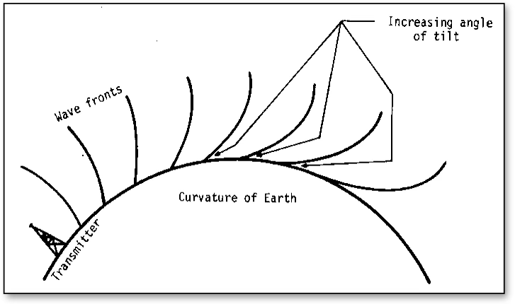
at earth’s surface, radar line-of-sight horizon is the maximum allowable separation (R) based on transmitter (ht) and receiver (hr) height
radio waves bend
optical waves don’t bend (much)
magnetic fields induce electric fields
electric fields induce magnetic fields
fields are perpendicular to each other
optimum dipole length (antenna length) for free space antenna is λ/2
optimum length for grounded antenna is λ/4 (reflection from ground)
fine the optimum antenna size for a ground-plane (quarter wave) dipole used to broadcast commercial radio (~1MHz)
λ/4 f=10^6 Hz C = fλ → c/f = λ
3×10^8m/s / 10^6 1/sec = (cross out sec) = 300m
λ/4 = 300/4= 75m
polarization
antenna is said to be polarized in the direction of the electric field (electric field is parallel to dipole axis)
when electric lines of force are horizontal,
the wave is horizontally polarized
if transmitting antenna is close to the ground,
vertically polarize
if transmitting antenna is high above the ground,
horizontally polarize
for most efficient communication (polarization),
transmit and receive antennas should have same polarization
circular polarization is used for satellite comms to eliminate the needy to try to match the receiving antenna to the orientation of the satellite
DIPOLE Antenna Distribution
energy radiates out the sides most strongly at the perpendicular and decreases in intensity such that no energy comes out the ends
results in donut shape, with antenna at “hole”
due to this, dipole antenna have some preferred direction (directionality)
Directional Antennas
antennas can be made even more directional via beamforming
directionality allows us to be more efficient with our energy (send it where we want it to go)
two ways to achieve directionality
antenna arrays
quasi-optical reflectors
bea forming
for radar systems, its a desirable to concentrate radiated energy into directional beam (flashlight)
this can “illuminate” a specific area in space to determine location from which reflected energy is returned
this helps us to know where someone is
Antenna Arrays
linear antenna arrays are used to concentrate radar energy to obtain directivity
arrange two or more antennas in such a way that their fields add together in specific directions and cancel in others
form of interference
two most common types of linear arrays are broadside and endfire arrays
difference between broadside and endfire arrays
what axis the constructive interference occurs on, which determines where the field is strongest (what direction the wave will travel in)
endfire and broadside arrays picture

linear arrays- directional beams
beamwidth can be predicted theoretically: θ = kλ/L
θ= beamwidth (radians)
k = depends on antenna shape; 0.88 for linear antenna
λ = wavelength
L = overall length of array
narrow beamwidth is desirable in order to improve resolution and therefore target identification and weapon targeting. if USAF C130 gunship requires new targeting radar with 2.2 Ghz frequency to have a beamwidth of .005 radians
with beam width, θ=kλ/L, what would be overall length of linear radar antenna array?
1st. find wavelength
λ= c/f = 3×10^8/2.2×10^9 = 0.136m
2nd. apply equation to beamwidth
θ = kλ/L → 0.005rad → 0.88 × 0.136m / L
L = 24m
quasi-optical reflectors
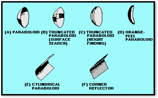
reflecting EM waves can be used to narrow the beamwidth, which increases directivity
parabolic reflectors primarily used
reflectors are made of sheet metal or wire mesh
Parasitic Reflector
broadside and endfire arrays are still not optimum because their main beams go in 2 directions
parasitic element is a conductor that creates EM wave that will somewhat cancel on one side of the antenna and reinforce on the opposite side
beam width target position accuracy
wide beam width
target can maneuver within beam without noticeable bearing/alt change
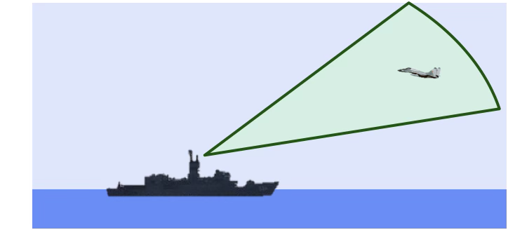
beam width target position accuracy
narrow beamwidth
target positional accuracy increased dramatically. any movement results in new bearing/alt

interference and 1-d arrays
single dipole radiation pattern

interference and 1-d arrays
2-dipole radiation pattern:
green = constructive interference
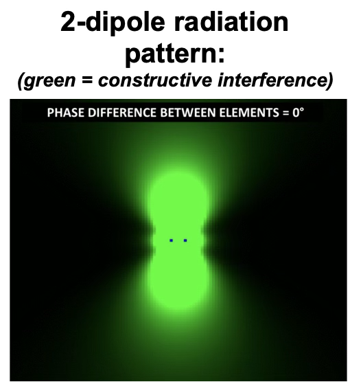
interference and 1-d arrays
10-dipole radiation pattern
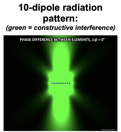
from 1-d to 2-d arrays
1-dimensional linear arrays can only focus the main lobe in azimuth or elevation
it takes a 2-dimensional array to focus a beam in both azimuth and elevation
moving the beam: MSA vs. ESA
MSA: mechanically steered array (physically moving array)
ESA: electronically steered array (“phased array”)
antenna array beams can be steered either way
phased array antennas=
electronic scanning
SPY-1A

electronic scanning adv and disadv
ESA advantages
beam can move instantaneously
fewer moving parts to break
high data rates
instantaneous beam positioning
no mechanical breakdown
increased flexibility
“multimode” operation
air/sea search
fire control
multi-target tracking
ESA disadvantages
lost efficiency at high angles off array boresight
steer beaming main point
for an array (bunch of emitters spread out in real physical space) you can adjust each angle to cause destructive or constructive interference at different spots or in 1 direction
if you change delay, the emitter might be more spread out
RADAR
radio detection and ranging
extend the environment beyond our own eyes and ears which therefore extends detection ability
adv of RADAR
can see through conditions that impair visual detection (night, fog, clouds)
longer than visual LOS range
gives accurate measurement of range and relative motion (more so than just eyes)
gives accurate measurement of azimuth and elevation
accurate info fed into fire control systems much more efficiently than human capable of doing
disadv of RADAR
poor target resolution (2 targets can look like one if close together)
poor ID capability
basic pulsed radar
most widely used technique, “conventional” radar
“on” for a short period and “off” for a long period
based on electromagnetic pulse that’s sent out into the environment and waited on for ‘echo’ (reflection)
utilizes speed of light to measure range of echo

pulse repetition time (PRT)
elapsed time btwn beginning of one pulse transmission and beginning of the next
must be long enough to allow echo pulse to return from system’s maximum range
this is to avoid missing an echo due to it being drowned out by next pulse
we commonly use pulse repetition frequency (PRF), expressed in Hz, instead of PRT- number of pulses per second
PRF = 1/PRT
pulse width (PW)
active transmit time or duration of the EM pulse (μsec)
minimum range at which target can be detected is determined by pulse width
rest time (RT)- nontransmit time
interval btwn pulses
pulse transmission relationships
pulse repetition time (PRT) = PW + RT
pulse repetition frequency (PRF) = 1/PRT
duty cycle = (PW)(PRF) = PW/PRT - Pavg/Ppeak
pulse transmission example problem
a 50 MHz RADAR has rest time of 18 milliseconds and pulse width of 2 milliseconds. calculate duty cycle
PRT = PW + RT = 2ms + 18ms
duty cycle =
PW / PRT = 2ms / 20ms = 0.1
basic radar components
transmitter
receiver
power supply
synchronizer
duplexer
antenna
display
transmitter
generates high-power pulses under control of a timer
receiver
converts incoming EM waves into electrical signals to be used by processor
power supply
furnishes all electrical voltages required for operation and interaction of system components
synchronizer
timer that supplies controlling signals to determine timing of the transmitted pulses
duplexer
switch that allows antenna to go from transmitting to receiving
antenna
receives radio frequency energy from transmitter and radiates it in a directional beam
display
produces visual indications of received pulses
basic pulse RADAR components
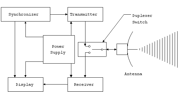
minimum range
while transmitting, RADAR is unable to listen for echo
if target’s echo returns while RADAR transmitting, target is undected

range resolution
minimum distance btwn 2 targets, in direction of range, resolved

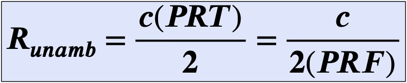
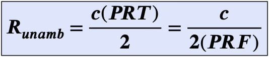
max unambiguous range, Runamb
max range a target can be that provides accurate calculation of range
beyond Runamb, target returns arrive after subsequent pulses are sent out such that RADAR uses the wrong ∆t to calculate range
unambiguous return, ambiguous return
return of echo prior to transmittal of next pulse (w/ unambiguous range)
echo from first pulse arrives after 2nd pulse sent
Runamb in real time
a tanker at Runamb — at the distance where its return arrives just as the next pulse is sent
exceeding Runamb
tanker is so far away that its return arrives AFTER subsequent pulse is sent
calculated range will be much closer than actual range, since RADAR is using the wrong (∆t )
PRT / PRF
PRT (μs) — time delay btwn successive pulses
PRF )Hz) —1/ PRT
lower PRT (higher PRF) gives
more updates per second (good)
higher probability of detecting targets (good)
reduced Runamb (bad)
PRT / PRF fire control RADARS and search RADARS
fire control radars
use high PRT for fast update rates
search radars
use low PRF
compensate through slower scan or wider beam
HIGH PRF will improve resolution BUT decrease Runamb
beamwidth vs. accuracy
search radar
wide beamwidths
sacrifice accuracy
targeting radar
narrow beamwidths
more accuracy

pulse radar effectiveness three key ranges
Rmax
assumes nothing blocks propagation
depends on RADAR characteristics, target characteristics, spreading
RLOS
assumes signal is strong enough to propagate out and back
depends on receiver height, target height, curvature of earth and bending of radio waves
Runamb
dependent on PRF only
pulsed radar effectiveness, in order to receive a detectable return:
R ≤ Rmax
R ≤ RLOS
pulsed radar effectiveness in order to get range to target correct:
R ≤ Runamb
signal reception
the return energy from a distant target is only a fraction of the transmitted energy
therefore, the function of a radar receiver is to receive weak target returns and amplify them to provide the desired target info
the effective range of a radar is therefore correlated to how weak of a signal the receiver can use
THE WEAKER THE SIGNAL THE RECEIVER CAN PROCESS, THE GREATER THE EFFECTIVE RANGE
“simplified” range equation
Rmax = max range of radar system
Pxmit = transmitted power
G = power gain
σ = radar cross section of target
Ae = antenna effective area
Smin = minimum signal for detection

transmitter power
high peak power is desirable to achieve max ranges
but lower power supports being covert
sometimes power is a design parameter
sometimes power is a design constraint
→ …power output @ high-power amplfier → P = Pxmit
power out
if pulse radiates uniformly in all directions, the power density at any given point would be:
“power density”