Finals-Engineering Graphics
1/115
There's no tags or description
Looks like no tags are added yet.
Name | Mastery | Learn | Test | Matching | Spaced | Call with Kai |
|---|
No study sessions yet.
116 Terms
Technical Drawings serve one of three purposes:
1) visualization
2) Communication
3) Documentation
Stages of Design Process
1) Problem identification
2) ideation
3) Refinement/Analysis
4) implementation/ Documentation
Concurrent Engineering
systematic approach that integrates the design and manufacture of products with the goal of optimizing all elements involved in the life cycle of the product (Efficient and saves money)
Sequential Engineering
Step by step approach to product development where each phase must be completed before the next begins. (Time is wasted and inefficient)
Life Cycle design
includes all aspects of a product except disposal and recycling.
Types of projections
Broken down into 2 main types: Perspective and parallel
Phantom line
Thin line of alternating long and short dashes. used to show alternate positions for moving parts and the positions of related or adjacent parts, and to eliminate repeated details
Cutting plane line
thick, dashed line used in technical drawings to indicate where an imaginary cut has been made through an object to reveal its interior features
Short-Break line
thick lines to indicate a break in an object, essentially showing that a part of the object has been shortened to save space on the drawing, while assuming the removed section is identical to the visible parts on either side
Centerline
Dark thin line which is just 3 dashes (long short long with the short dash in the middle)
Shows the axis of symmetry for a feature or part
indicates path of motion
shows the location for bolt circles and other circular patterns
Symmetry Lines
Dark, thick lines. indicates the axis of symmetry on an object
Dimension line
Thin line with arrowheads at each end that indicates size
Hidden line
Dark and thin dashes. lines in technical drawings that indicate edges, surfaces, or corners that are not visible from a given viewpoint
Visible line
a solid, thick line that outlines the visible edges and surfaces of an object
Section line
thin, parallel lines that indicate the cut surfaces of an object in a section view (Usually at an 45 degree angle)
Extension line
thin, vertical line, used to demonstrate the extent of a dimension or to indicate the boundaries of an object, often extending from the object to the dimension line.
Long-break line
thin solid lines that have zigzags to indicate a break
Drawing scale
the reduction or enlargement of the drawn object relative to the real object
Sens serif
means letters without this curves or spurs
Lettering standards
3 mm (1/8 in) tall
Sans serif
Spacing of letters and words
Letters:
- DO NOT SPACE YOUR LETTERING CAUSE IT WILL APPEAR UNEQUAL
Words
- Be sure to leave space between rows of lettering, usually equal to the letter height
Standard US sheet size measurements
A) 8.5×11 inch
B) 11×17 inch
C) 17×22 inch
D) 22×34 inch
Surfaces can be one of the following four types
1) planar
2) single curved
3) Double curved
4) Warped
Contours
Contrast between the positive and negative space
Edges
solid formed where 2 surfaces intersect
Vertices
A vertex of a solid is formed where 3 or more surfaces intersect
Point
Used to represent a location in space, has no width height or depth
Line
Used to represent the edge of a solid object
Important skills for sketches and drawings:
1) Accuracy
2) Speed
3) Legibility
4) Neatness
4 principle types of projection
1) Multiview
2) Axonometric
3) Oblique
4) perspective
Six standard views
top, bottom, left, right, front, and back
3 principle dimensions
1) height: Shown in the rear, side, and front views
2) Width: shown in the rear and top views
3) Depth: Shown in the side and bottom views
Third angle projection
Views are produced as if the observer is outside looking in. Mostly used in the US
First angle projection
Object is placed above the horizontal plane and in front of the vertical plane. Object is in the 1st angle
Precedence of lines
1) Visible
2) Hidden
3) Cutting
d) Centerlines
e) phantom
Views of surfaces
normal, inclined, oblique
3 aspects of good dimensioning
1) Technique of dimensioning
2) placement of dimensions
3) Choice of dimensions
Tolerance
The total amount that the feature on the actual part is allowed. Vary from what is specified by the drawing or model dimension
What are the lines used in dimensioning?
Dimension line, extension line, and centerlines
Dimensioning rules
1) There should be a visible gap between object and origin of extension line
2) Do not cross dimension line
3) Preferred dimension placement is off the view (NEVER INSIDE)
4) Each feature of an object is dimensioned once and only once
5) dimension lines should be aligned and grouped where possible to promote clarity and uniform appearance
6) when extension lines cross DONT BREAK. Break line when extension and dimension line meet
Leader
Thin, solid line directing attention to a note or dimension and starting with an arrowhead or dot
Leader rules
do not make leaders parallel to nearby lines of a drawing
do not make leaders through a corner of the view
do not make leaders horizontal or vertical (45 degree angle)
Reference
( )
Countersink
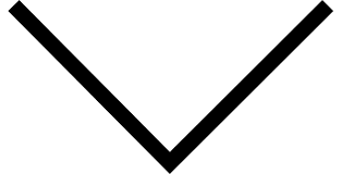
Depth
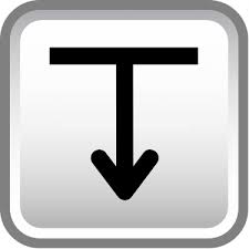
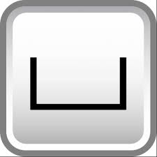
Spot face

Counterbore
Arc length
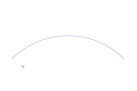
Slope
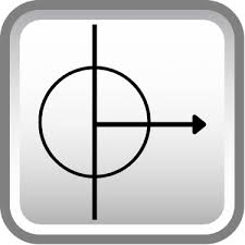
dimension origin
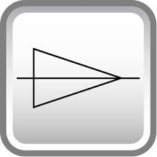
conical taper
Places, times, or by
X
Superfluous Dimensions
Unnecessary dimensions
Dimensioning Angles
Angles are dimension by specifying the angle in degrees and a linear dimension
Dimensioning Arcs, fillets, and rounds d
Circular arc is dimensioned in the view where its true shape is seen by giving the value for its radius and preceded by the abbreviation R.
Dimensioning cylinders
Cylinders are usually dimensioned by giving the diameter and length where the cylinder appears as a rectangle
Dimensioning holes
The leader of a note should point to the circular view of the hole (if possible)
Finish mark
Used to indicate that a surface is to be machined, or finished, as on a rough casting or forging.
3 basic application of threads
1) To hold parts together
2) To provide for adjustment between parts
3) To transmit power
Axis
Imaginary line that runs through the center of a thread screw
Pitch
distance parallel to the axis between corresponding points on adjacent threads
Root
Bottom of the groove between two sides of a thread
Crest
highest point on a thread
Side
Also called the flank
Minor diameter
smallest diameter of the thread
Major diameter
largest diameter of the thread
Pitch diameter
diameter of an imaginary cylinder that passes through the thread profile
Depth
Distance between the base and the crest of the thread, measured perpendicular to the axis
⌀.6562-↧1.38 ¾ -10 NC-2B LH-↧1.00
What does ¾ represent?
Major diameter of the thread
⌀.6562-↧1.38 ¾ -10 NC-2B LH-↧1.00
What does ⌀ represent?
Diameter
⌀.6562-↧1.38 ¾ -10 NC-2B LH-↧1.00
What does 10 represent?
Threads per inch
⌀.6562-↧1.38 ¾ -10 NC-2B LH-↧1.00
What does N represent? (NC)
National (form)
⌀.6562-↧1.38 ¾ -10 NC-2B LH-↧1.00
What does C represnt? (NC)
Course thread series
⌀.6562-↧1.38 ¾ -10 NC-2B LH-↧1.00
What does 2B represent?
Class of fit
⌀.6562-↧1.38 ¾ -10 NC-2B LH-↧1.00
What does LH represent?
Left-hand modifier
MJ 10 × 1.5
What does M represent?
Metric thd
MJ 10 × 1.5
What does J represent?
Metric thd form
MJ 10 × 1.5
What does 10 represent?
Major Dia pitch of thd
MJ 10 × 1.5
What does 1.5 represent?
Pitch
1.125-5 ACME - 2G (21)
What does 2 represent? (2G )
Class of fit
1.125-5 ACME - 2G (21)
What does G represent?
Thread type
1.125-5 ACME - 2G (21)
What does (21) represent?
Thread gaging system
3 types of helical springs
1) Compression - offer resistance to compressive force
2) Extension -offer resistance to compressive force
3) Torsion- mechanical spring that works by exerting torque or twisting force when it is twisted along its axis.
Runouts
Used to represent filets that connect with plane surface tangent to cylinders
Partial View
A view may not need to be complete but needs to show what is necessary to clearly describe the object
Removed view
complete or partial view removed to another place on the sheet so that it is no longer in direct projection with any other view
Section views are used for 3 main purposes
1) To document the design and manufacture of single parts that are manufactured as one piece
2) to document how multiple parts are to be assembled or built
3) to aid in visualizing the internal workings of a design
Cutting plane view
Appears edgewise as thick dashes line called cutting line plane. The arrows at the ends of the cutting-plane line indicate the direction of sight for the sectional view.
Visible edges
Newly visibly edges cut cutting plane are crosshatched with section lining
Placement of section views
section views can replace standard orthographic views
Rules for lines in section views
Show edges and contours that now visible behind the cutting plane
omit hidden lines in section views
A sectioned area is always completely bounded by a visible outline-never by a hidden line
A visible line can never cross a sectioned area in a view of a single part
Section-lining technique
uniformly spaced by an interval of 2.5 mm
not too close together
Uniformly thin
distinctly thinner than visible lines
Lines should NEVER be parallel/ perpendicular to outline
Half section
exposes the interior of half of the object and the exterior of the other half. (symmetrical)
Broken out section
It often happens that only a partial section of a view is needed to expose interior shapes.
Revolved section
The shape of the cross section of a bar, arm, spoke or other elongated object can be shown
offset section
in sectioning complex object, it is often desirable to show features that do not lie in a straight line by “Offsetting” or bending the cutting plane.
(Remember the moving thing Prof did to look at inside parts of a shape that was not in a straight line)
Ribs in section
To avoid giving a false impression of thickness and solidity, ribs, webs, gear teeth, and other similar flat features are not hatched with section lining even though the cutting plane slices them
Aligned section
When parts with angled elements are sectioned, the cutting plane may be bent to pass through those features. The plane and features are then imagined to be revolved into the original plane.
Conventional Breaks and sections
Used to shorten the view of an object that is too long to show clearly at one scale on the drawing sheet
Auxiliary plane
To show the inclined surface true size, the direction of sight must be perpendicular to the inclined plane.