IAT 106 Terminology
1/121
There's no tags or description
Looks like no tags are added yet.
Name | Mastery | Learn | Test | Matching | Spaced |
|---|
No study sessions yet.
122 Terms
Sketches
We use sketches to communicate to ourselves and others
Orthographic projection
2D Plane, projective view is parallel with perspective projection (At infinity).
(Standard means of graphically representing objects)
Multiview method
Splitting orthographic projections into 3 segments (Usually top, front and side)
Bounding rectangle
A frame used to capture the correct aspect ratio of a 3D Object
Hidden Line
Image on your right
Visible Line
Image on your right
Centre Line
------------------- - -------------------
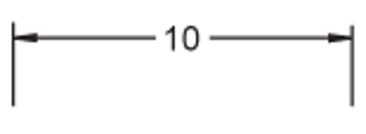
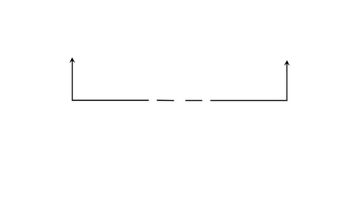
Dimension and Extension Lines
Image on your right
Phantom line
Represents objects in motion (ie where it was before moving)

Cutting Plane Line
Indicates the location of imaginary cut made to reveal interiors.
Construction Line
(not to be mistaken with visible line, it's slightly lighter.)
Line Hierarchy
Visible > Hidden / Cutting Edge / Section Plane > Center > Break > Dimension/ Extension > Section
Dimensioning
Used to specificy size, location and tolerance (?)
Dimensioning Circles
An arc with more then 1/2 the circle is labeled with the diameter sign
An arc with less then 1/2 the circle is labeled with "r"
Relative Dimensioning
objects locations and dimensions are based off the prior object, originating off inconsistent baselines, this makes the entire structure far more prone to error. There is NO baseline
Coordinate dimensioning
Objects dimensions are scaled and measured from a singular shared point which they all originate from. More accurate, avoids tolerance build up
Infinity Planar View
Viewing an object at a "perfect" parallel.
Projection plane
"Glass wall" we view objects from
Projection
Intersection between projectors and projection plane (the object)
Intersection point
point where lines intersect and connect an object to form its unique shape. (ie. where 2 perpendicular lines may meet)
Perspective Projection
Utilizing a finite viewpoint (Projectors are not parallel) (Looking at an object at an angle)
Forms a realistic view of the object
Parallel Projection
A viewpoint that is infinite. Used to view multigraphic and orthographic planes
Natural View
An object in its natural orientation (ie a car is drawn on its wheels, a person on their legs)
Edge
The intersection of two surfaces
True Length
Parallel to the plane of projection in a Multiview projection.
Oblique Surface
not parallel to any plane of projection (CC)
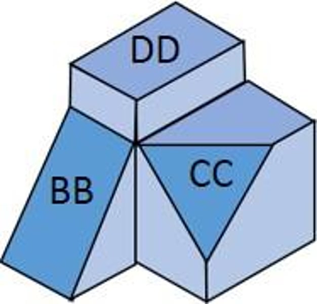
Inclined Surface
Slanted surface that can be viewed fully in at least one viewpoint. (BB)

Principle Surface
Can be viewed in at least 2 viewpoints. (DD)

Viewpoint
Where the observer stands in relation to the projection plane and the object
Projectors
"Lines" of sight (Indicate if the object is being viewed from infinity or not)
Sketched Features (OnShape)
Shape features have sketches and based on sketches
Sketched features are built from 2D Sketches
Operation Features (OnShape)
Do not utilize sketches
Applied directly to work piece by sketching edges or faces
Isometric projections
True representation of the isometric view of an object
obtained by rotating the object 45 degrees about a vertical axis, then tiling it forward by 35.6 degrees.
(Isometric axes meet at A, B and form equal angles of 120 degrees in the isometric view)
Number of views of the projection are?
Infinite.
Isometric axes positions
Regular Isometric
Reverse Isometric (Basically turn the isometric view inverse)
Isometric Lines
Lines parallel to a "leg" of the isometric axes
Non Isometric Lines
Oblique, or inclined. They are not parallel to a "leg" of the isometric axes
Isometric plane
Any plane parallel to the isometric surfaces formed by 2 adjacent isometric axes.
Glass Box Method
Split an object into 6 views (as if it was encased in a glass box) --> Unfold for Multiview
Pictorial views
Enables use to show several faces of an object at once.
Also represents an object in 3 dimensions.
(Used in technical docs, sales literature, maintenance manuals, architectural drawings)
Axonometric views
Parallel to line of sight, perpendicular to picture
Sorted into Trimetric/Dimetric/Isometric (Names are self explanatory)
Oblique --> Parallel to line of sight
Perspective --> 3 Dimensional, vanishing points only front face, outlines are parallel.
Parallel Projection Technique
Creates a pictorial drawing of an object by rotating the object on an axes relative to a projection or picture plane.
Isometric Axes
Projection of angles now make 120 degrees with each other.
Oblique Lines
Lines that aren't parallel or perpendicular, but rather, slanted.
MITRE Line
Diagonal Line in Multiview drawings
Perspective Drawing
the most realistic form of sketching 3D objects.
Best way to mimic the human eye
a mathematical system for creating the illusion of space and distance on a flat surface
Convergence point
When lines run parallel to teach other away from the viewer, they appear to converge at one point into the distance
Tracing rays
rays of light from an object to a point
pinhole
The pinhole represents the eye in perspective drawings.
Horizon Line
The plane that's on our eye level.
Vanishing point
A point in the horizon where the convergence point is located, and objects seem to "disappear".
Ground point
The point on which the object rests
Station point
represents the eye position of the observer
Picture Plane
A plane on which object is projected and where lines of sight from object form an outline of it.
The position of the picture plane determines the size of the projected object.
If the picture plane is in front of the object, the object appears smaller.
If the picture plane is in front of the object, the object appears larger.
Ground Line relation with horizon line
This determines the type of perspective view used.
Birds eye view
Human eye view
Ground eye view
Worms eye view
Types of perspective drawings
There are three types based on the number of vanishing points needed to capture the three primary directions
one-point perspective
two-point perspective
three-point perspective
one-point perspective
all lines converge at one point
horizontal and vertical lines are parallel to the projection plane
two-point perspective
2 convergence points
Occurs when only one principle direction is parallel to the projection plane.
three-point perspective
Lines appear to convergance at three vanishing point. Either to the sides of the picture plane, or at the top/bottom of the page.
No line is parallel to projection plane
Auxiliary View
A means of projecting "true proportions of an object." Used to draw oblique and inclined edges, which cannot be accurately show in Multiview.
Auxiliary views are perpendicular to the face for which you seek a true shape view
It is an orthographic view that is not one of the six standard projection (top right left bottom ect.)
Principle face
appears as a polygon in one view and edges in the other two views
Inclined face
appears as a polygon in two views and an edge in the other view
Oblique face
appears as a polygon in all three views
Principal edge
appears as an edge in one view
Inclined edge
appears as an edge in 2 views
Oblique edge
appears as an edge in all 3 views
Foreshortened
When an inclined surface is depicted as shorted then it's "true length" in a Multiview drawing.
Secondary Auxiliary view
Projected plane from a primary auxiliary view
Tertiary auxiliary view
projected plane from a secondary or another tertiary auxiliary view.
Partial Auxiliary View
Easier to draw and understand, focuses on just one segment of a plane
Cross sections
Using a cutting plane line, an object is subsequently split.
This is used to depict complex interiors and clarify objects shapes.
The cutting plane line MUST face the direction opposite of the cut. (If you have cut the left side of an object, the cutting plane must point to the right).
Convientional Break
same principle as a cross section, utilized to shorten an object so that it may fit in a drawing and allow proper scaling.
If there's a really long pole in your design, consider using a conventional break to shorten it so that your drawing will be easier to view in regards to the rest of it.
Degrees of Freedom
Refers to an objects ability to move along the (x, y, z) and rotational axis
The number of axis's an object can move around is proportional to the number of degrees of freedom it will possess. EG an object that can move on the x and y axis transitionally, but is unable to rotate has "2 degrees of freedom."
Fastened Mates (On shape function)
A tool used in assembly to manipulate degrees of freedom an object may possess. (ie: restricting an object to just moving on the x dimension.)
ambigious
When a Multiview doesn't have enough views to fully describe the object. (from 2 to 6 views)
Radius constraints when dimensioning
Should only be applied when you are dimensioning less then half a circle
Principle Orthographic views
Camera can be anywhere, infinite number of views .... refer to slides
Size relationship
Cross reference dimensions in Multiview's to avoid re iterating pre-existing dimensions, make sure that said dimensions align
Perspective view
The observer is at a finite distance from the object
Pictorial Display
Refers to when you can see multiple perspectives? Iterations? Of the object. Its a perspective display (I think?)
Three important elements of spacial thinking
Concepts of space (relationship of measurement)
Tools of representation (how we communicate structure, operation, object function)
Process of reasoning (how an operation operates)
Descriptive function
capture, preserve, and convey the properties of the relations among objects
Analytic function
understanding of the structure of objects
inferential function
generate answers pertaining to the evolution and function of objects
Datum line
base line for coordinate/relative dimensioning
tolerance
the amount a measurement can vary before it messes up the design
Baseline
????
wireframe
edges+ vertices (ambigious)
Surface models
edges and vertices and faces
Solid Models
3D models of a computer
Three purposes of spatial thinking
Descriptive function
Analytic function
Inferential function
Tolerance
The deviation of an objects dimensions from its original form with each new iteration, or addition. Prevalent in relative dimensioning.
Projection relations - Oblique
The object is parallel to the projection plane, however the projection rays/lines are angled
Projection relations - Orthographic
Object in relation to projection plane is perpendicular, projection rays are perpendicular.
Projection relations - Isometric
Object in relation to projection plane is angled, however, projection rays are perpendicular
Pictorial Projection
Refers to any projection in which several faces of the object are shown at once (encapsulates Multiview I guess, axonometric, oblique)
Surface Labelling
Labeling pictorial views
Vertex Labeling
Labeling according to orthographic views or Multiview's
3D Modeling technique - CAD Modeling
Modeling with the help of a software such as ONshape or SOlidworks
3D Modeling technique - Features based modeling
Using one sketch, then using on shape operations on it to create the desired object.