Oilers Exam Mass Maritime 2026
1/73
There's no tags or description
Looks like no tags are added yet.
Name | Mastery | Learn | Test | Matching | Spaced | Call with Kai |
|---|
No analytics yet
Send a link to your students to track their progress
74 Terms
Classify the main generator engines onboard the Patriot State. Include the number of engines, and pertinent specifications.
Manufacturer: GE Wabtec
Model: 16 V250MDC
Type: Turbocharged, 4-stroke, single acting, trunk
piston, non-reversible, direct fuel injection
No. of sets: 4
List and describe the types of engine alarms associated with the Main Generator Engines (MGE) onboard Patriot State.
There are two types of alarms in the control system: Diagnostic Alarms and Engine Protection Alarms.
Diagnostic Alarms indicate non-critical issues like wire loss, short circuits, communication failures, sensor faults, and power failures. These should be addressed at the earliest opportunity but do not immediately impact engine operation.
Engine Protection Alarms relate to operational parameters and have multiple protection levels:Warning: Informational, non-critical, requiring timely investigation.Slowdown Request: Suggests reducing engine speed/load to correct issues like high cooling or LO temperatures but does not happen automatically.Speed Restriction: The system automatically reduces engine speed due to serious conditions requiring urgent attention.Engine Load Limited: The system automatically reduces engine load to protect against critical conditions.Shutdown: The system shuts down the engine due to critical failures requiring corrective action before restarting.
Detail the starting procedure for the main generator engines onboard Patriot State. Include checks that are required before starting an engine.
a) Blow down the air start receivers to ensure that water will not
enter the air starter.
b) Ensure that the engine oil level is 'FULL'.
c) Ensure that there is sufficient coolant water is present by verifying the level in the expansion tank sight glass.
d) Ensure that sufficient fuel for engine operation.
f) Prime the fuel system, if required.
e) Ventilation
g) Inspect the engine to ensure that no leaks or other signs of damage are present.
h) Ensure proper heating of engine cooling water
i) Ensure that the engine has been preubricated.
Describe at least four (4) of the associated systems that support and or supply the main generator engines onboard Patriot State.
The Cooling Water System uses fresh water to cool the cylinder jackets, heads, and charge air. The HT system cools the engine and regulates the EGR cooler, while the LT system cools the LO and second-stage charge air. Engine-driven and electric pumps circulate water, and a preheater warms the system before startup. The EGR cooler helps reduce NOx emissions.
Describe the Low Temperature Fresh Water Cooling System and list at least 6 consumers that it provides to onboard Patriot State.
2 LTFW cooling systems, 1 supplying to engine room 1 and 1 supplying engine room 2. The LT system is self contained and gets replenished from the distilled water system. 3 LT fresh water pumps are fitted to each circuit, 2 as duty pumps 1 on stand by. Supplies bow thruster, main engine propulsion transformer, main engine frequency converter, main engine braking resistor, main engine propulsion motor, main generator alternator, starting air compressors
How many low temperature fresh water cooling pumps are located in each engine room? How many of these pumps are operating at a time? What types of pumps are these?
There are 3 LT FW cooling pumps in each engine room. 2 of these pumps are operating at all times with one on standby. They are vertical centrifugal pumps.
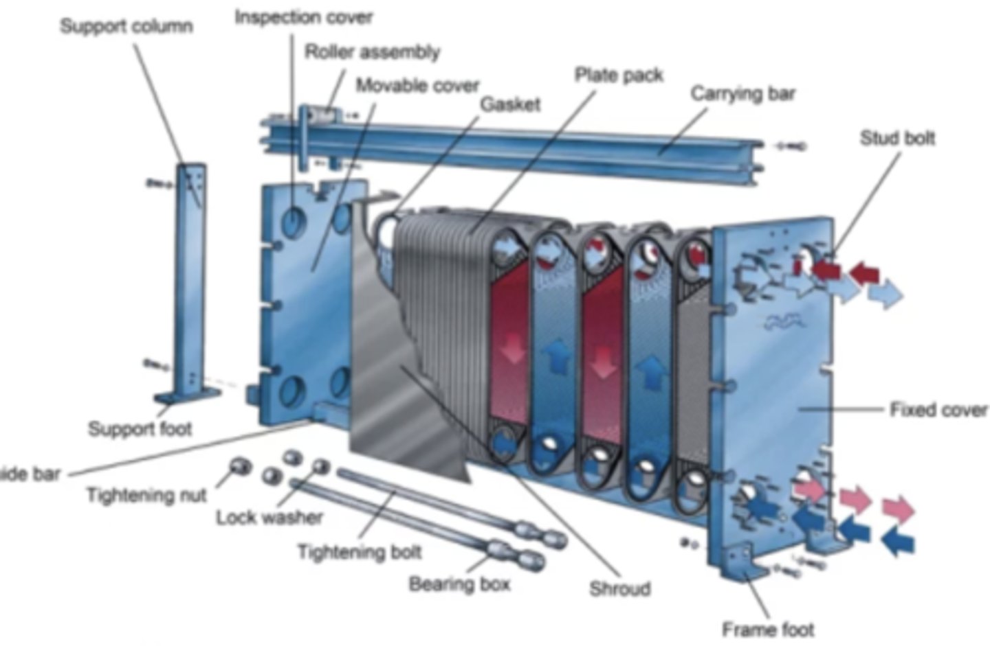
What type of heat exchangers are utilized to reject heat from the fresh water cooling system? Make a sketch of these types of heat exchangers
Plate type
What is the purpose of the high temperature fresh water cooling system? What does this system absorb heat from specifically and where can it reject this heat to?
The HT freshwater is used as jacket water to cool the cylinders on the main diesel generators. The system expels this heat in the HVAC water heater and the Distilled Water Generators and finally to the f cooling. There is only one DWG is only located in engine room 1.
Why is an expansion tank utilized in the high temperature and low temperature fresh water cooling systems onboard Patriot State?
Each LT cooling system has its own expansion tank, which is replenished with distilled water. The tank accommodates expansion, provides make-up water, and maintains pressure head.
Besides the main generator engines, identify and describe two other pieces of equipment that the high temperature fresh water cooling system supplies onboard the Patriot State.
The HVAC water heaters use heat from the MGE HT cooling water system to warm glycol/water, which circulates through the accommodation's Air Handling Units and Fan Coil Units. Two pumps per circuit circulate the glycol/water, and these heaters are only used in cold climates.
The Distilled Water Generator located in engine room 1, produces 10 tons of distilled water daily using heat from the MGE HT jacket water system. A three-way temperature control valve regulates the temperature if excess heat is available or if the system is shut down.
How many sea chests are there on Patriot State that are utilized for sea water cooling systems? Where is each located and what are each of the designated in each space?
There are 8 sea chests on board the patriot state. There are 2 locates in each engine room, as well as 2 in amr 2 and 2 in amr 3. The engine room sea chests are utilized to cool the high and low temp freshwater cooling systems.
List the quantity, type, and capacity of the main seawater cooling pumps in each engine room onboard Patriot State.
There are three vertical centrifugal pumps for seawater cooling per engine room. 2 running and one standby. Capacity is 220 m^3/h at 2.7 bar
List the quantity, type, and capacity of the auxiliary seawater cooling pumps in each auxiliary room onboard Patriot State.
There are 2 auxiliary seawater cooling pumps along with 1 Auxiliary/bilge seawater cooling pump in both amr 2 and amr 3. They are vertical centrifugal. The auxiliary pumps are rated 190 m^3/h at 2 bar while the auxiliary/bilge pump has a capacity of 250/190 m^3/h at 2.8/2.0 bar
Detail at least 6 consumers in the sea water cooling system for the auxiliary machinery rooms and indicate which piece of equipment is associated with each auxiliary room.
No. 1 and No.2 fresh water generator in amr 2 and 3, gray water tank amr 1, waste water treatment plant amr 1 and 4, No. 1 & 2 provision refrigeration unit amr 3, water mist for emergency use in amr 2 and 3, A/C chilled water plants in amr 1 and 4
Is seawater cooling utilized in either of the motor rooms onboard Patriot State? Explain why or why not?
Yes in motor room 2 because the supply of sea water to the stern tube is essential to provide cooling and lubrication of the stern bearing when the propeller shaft is turning.
What is the MGPS system associated with the sea water cooling system? Explain the principle of operation of the MGPS.
Marine Growth Prevention System with copper and aluminum anodes. These anodes release ions that discourage microorganism growth and create an anti-corrosion layer in the system. The MGPS is automatic and requires minimal maintenance, adjusting the current to suit water flow. Incorrect current settings can lead to insufficient protection or rapid anode depletion. Regular checks are needed to ensure proper function.
What type of fuel is utilized onboard Patriot State? Explain how this fuel differs from that utilized on previous Massachusetts Maritime Training Ships.
Marine Gas Oil, it differs from heavy fuel oil because it doesn't need to be heated before it is transferred between tanks or sent to combust. It also has a lower btu content than heavy fuel oil
Detail the flow of fuel from the MGO service tank to the main generator engine injectors and include all relevant equipment that the fuel must pass through.
Starting at the MGO service tanks, the fuel first goes through a supply/flow meter. After the meter the fuel goes through a water separator then the fuel priming pump. After the fuel priming pump the fuel goes to the first stage fuel filter then to the high pressure fuel oil pump. After the HFOP the fuel goes into the common rail that is hooked up to all 16 injectors.
What is the purpose of the fuel oil separator system onboard Patriot State? Where does this system originate and where is the discharge of the system. Is this system located in both engine rooms?
The fuel oil separator system ensures that we have clean fuel in our fuel oil service tanks. The fuel oil separator system originates from the fuel oil settling tanks and discharges to the fuel oil service tanks. There are two systems in each engine room
How many fuel oil storage tanks are located onboard Patriot State? Where are they located?
There are 8 MGO storage tanks.
What is the approximate pressure delivered to the fuel injectors of the main generator engines onboard Patriot State? How is this accomplished and what is the name commonly given to this type of engine fuel delivery system.
The MGEs have Electronic Fuel Injection systems, which comprise of a Low Pressure system and a High Pressure common rail fuel system.The fuel injectors deliver atomized fuel into the cylinders. An integrated solenoid valve controls the timing, and duration of fuel injection. There is one injector in each cylinder head. The fuel oil injector receives the fuel from the fuel injection pumps, and atomizes the fuel as it is delivered to the combustion chamber. The injector acts mainly as a valve. The HPFP generates the pressure required for proper fuel injection. There are two high pressure fuel pumps, located on
Detail several distinct pieces of equipment that utilize a forced lubrication system onboard Patriot State?
Main Engines, Propulsion Electric Motor, Thrust Bearing, Intermediate shaft bearings
How is cooling provided for the lubricating oil for the main generator engines on Patriot State? Is the cooling provided considered to be "high temperature" or "low temperature"?
The cooling of the lubricating oil is provided by a cooler and a thermostatic regulating valve. The cooler uses the low temperature cooling water system and cools the LO through heat transfer across the surface area of stainless steel pipes. It is considered LT
Explain the purpose of the propulsion motor lubricating oil system? Is this system integrated with the generator engine lubricating oil system?
The purpose of the PEM lubricating oil system is to ensure proper lubrication and cooling of the motor bearings, especially during startup and low-speed operation . It uses jacking pumps to lift the motor shaft and prevent bearing damage. Once above 55 rpm, self-generated oil films take over. The system includes alarms for temperature, pressure, flow, and oil level to maintain safe conditions. The PEM lubricating oil system operates independently from the generator engine lubricating oil system, focusing solely on the motor bearings
Indicate the two pieces of equipment that are used to generate fresh water onboard Patriot State. Include the basic operating principle for each and where they are located onboard the vessel.
The Fresh water generator and the reverse osmosis system. The FWG is located on the port side forward in engine room number one. The Fresh Water Generator produces 10 tons of distilled water per day using heat from the No.1+2 MGEs HT cooling water system. Sea water is pumped into the condenser, creating a vacuum that lowers the evaporation temperature. The evaporated water is condensed and separated from droplets by a deflector and demister, then transferred to the storage tank. The Reverse Osmosis located in amr's 2 and 3 fresh water generator produces clean water for drinking and vessel utilities by passing pressurized sea water through a semi-permeable membrane. The membrane allows water molecules to pass through while blocking most dissolved solids, which are discharged as brine. The system's output depends on factors like feed water temperature, salinity, and pressure. Temperature changes can affect output, and higher feed pressure increases flow. Regular monitoring detects fouling on the membranes, which can reduce output and damage the system if not properly cleaned. Sufficient concentrate flow is essential to prevent scaling and membrane damage.
What is the distilled / technical water system utilized for in the engine room of the Patriot State? Where is the distilled water tank located and where is the distilled water tank filled from?
MGO separators operating water.
• Chilled water systems.
• Gray water lift tanks.
• Gray water tanks.
• Waste water mixing tank.
• Bow thruster room fresh water expansion tank.
• Sewage sludge tank.
• BWTS system.
• Sludge pumps priming lines.
• Gray water lift drain tanks.
• Black water lift drain tank.
• Oily water separator flushing line.
• Stern tube quality water system pump suction.
• Stern tube cooling fresh water tank.
• LT/HT expansion tanks for MGEs x 4 sets.
• Engine rooms No.1+2 LT fresh water expansion tanks
• Engine room distilled water service outlets.
It is located in Engine room 1 and filled from the distilled water generator in engine room 1
Explain the function of the fresh water hydrophore tank and how it works. Make a sketch to support your answer.
a hydrophore tank is a key component in a water distribution system, particularly for maintaining constant pressure and flow in systems that rely on water for consumption, such as drinking water systems on ships or industrial applications. In your setup, it serves to store, pressurize, and distribute fresh water to various parts of the system, including UV sterilizers and consumption points.
Explain how potable water is treated onboard Patriot State. What equipment is associated and what essential function does each piece perform?
The fresh water is treated by a chlorinator to kill bacteria, then passed through a rehardening filter to adjust pH and add essential minerals for human consumption. The chlorinator dosing is automatic based on water flow, while the rehardening filter raises the pH to 7-8. A UV sterilizer further ensures the water stays sterile by using UV light to break down microorganisms.
Where is potable fresh water stored onboard Patriot State? How many tanks are utilized and where are they located?
There are 6 fresh water tanks, 3 in amr 2 and 3 in amr 3, they are first sent to the hydrophore tanks and also in amr 2 for water mist for accommodation and the roro space and in amr 3 for accommodation or the hot water calorifier
How is potable water heated and distributed on Patriot State? Describe the domestic hot water system in detail.
Cold potable water is heated in 10 calorifiers, which use electric heating elements to raise the temperature to 60°C . The temperature can be adjusted via thermostats. Hot water is then circulated through various systems by pumps, minimizing wastage by ensuring hot water is always available at taps without needing to run off.
Differentiate the starting air system, control air system, and service air system onboard Patriot State. Give examples of what each system is used for.
Starting Air System Purpose : Provides air to start the Main Generator Engines and can also back up other air systems in emergencies.
2. Control Air System ● Purpose : Powers control valves and other automated systems, like machinery and sensors.
3. Service Air System ● Purpose : Provides air for maintenance , powering tools , and general cleaning tasks.
Classify the compressors used for the starting air system. Provide as much technical information as possible.
Manufacturer: ATLAS COPCO Type:Two-stage reciprocating, fresh water cooled -Model:LT 30-30 W KE NO. of sets: 4 Capacity: 70m^3/h at 30 bar
Classify the compressors used for the control air system. Provide as much technical information as possible
Manufacturer: ATLAS COPCO Type:nScrew, water cooled 2 stage Model:ZT15-8.6 bar-60 No. of sets:2 Capacity:112m^3/h at 8 bar Motor:440V, 13.4KW
Classify the compressors used for the service air system. Provide as much technical information as possible.
Manufacturer: Atlas Copco Type: Screw, air cooled single stage No of sets: 1 Capacity: 5.4m^3/h at 9 bar Motor: 440V 30kW, 3565 rpm
Describe the various bilge suctions in the machinery spaces onboard Patriot State. How many bilge suctions are there in each engine room?
How is gray water separated from black water onboard Patriot State? Where is grey water collected and where does gray water join into the shipboard sewage system for processing?
Gray Water : Comes from sinks, showers, washers, galley (not toilets). ● Black Water : Comes from toilets (sewage). Grey water is collected in the grey water lift station tanks and then is pumped to the grey water tanks (2 in amr 1, 2 in amr 4). Black water and grey water meet in the mixing tank before it is sent through the waste water treatment system.
Explain the principle of operation for the vacuum collection units associated with the black water system onboard Patriot State.
EVAC
Type: Horizontal rotary lobe
Model: Online Flex 2Fx60
No. of sets: 2 per unit
Capacity: 600 liters/h (2.64gpm) at -0.5 bar (-51kPa)
The Black Water (BW) collection system uses two vacuum units, each serving different fire zones. No.1 unit serves Fire Zone 1, and No.2 unit serves Zones 3 and 4. The units are cross-connected, allowing BW to be directed to either tank for maintenance. Each unit has two vacuum pumps, with one operating and the other on standby. The collected BW flows by gravity to the associated BW tank.
Explain the MSD treatment process in detail for the Patriot State. What equipment is associated in this process?
The sewage treatment process begins by mixing black and gray water in a sewage mixing tank, which is then pumped into the treatment plant. The sewage mixture undergoes maceration to chop solids, followed by air enrichment in a saturator to help remove suspended solids. Flocculants are added, causing particles to form larger flakes that float to the surface, creating sludge foam. The clear liquid below is then transferred to a UV disinfection system, where UV light kills bacteria and microorganisms, rendering the sewage safe for discharge. The process includes continuous monitoring of pressure, sludge removal, and maintenance of system levels, ensuring efficient treatment.
Classify the oily water separator onboard Patriot State and give a detailed description of its principle of operation.
Stage 1 - Coalescence: ○ Bilge water enters and passes through a basket strainer to remove large solids. ○ In the coalescer there is a separating media matrix where , oil droplets combine into larger droplets due to gravity. These rise to the top and are collected as free ○ oil . 2. Stage 2 - Filtration and Membrane Separation: ○ The water then gets pumped by the feed pump and goes through a particulate filter (5 microns) to remove smaller solids.
○ Next, it's pumped by the process feed pump through SPIROLATOR membranes , which filter out emulsified oil and other waste. Clean water (less than 15 ppm oil) passes through, while the oil is rejected. 3. Oil Monitoring and Discharge: ○ The oil content monitor checks the water. If the oil level is too high, the water is reprocessed. If it's clean, the water is discharged overboard. Key Equipment: ● Feed Pump : Moves bilge water into the system. ● Macerator : Breaks up solids. ● Coalescer & Polishing Beads : Remove oil. ● SPIROLATOR Membranes : Separate fine oil and emulsified oils. ● Oil Content Monitor : Ensures discharge is under 15 ppm. ●
Explain the principle of coalescence as it applies to the oily water separator. How does coalescence take place in the Heli-Sep OWS onboard Patriot State?
Coalescence in the Heli-Sep Oily Water Separator (OWS) works by helping small oil droplets combine into larger ones so they can be easily separated from the water. How it works: 1. Bilge water enters the OWS and passes through a special filter (coalescer). 2. Small oil droplets stick together and form larger droplets as they move through the filter. 3. The larger oil droplets rise to the top, separating from the water. 4. The separated oil is collected and discharged, while the cleaned water continues through further treatment. Why it's important: ● Coalescence helps remove most of the free oil from the water, making it easier to separate and dispose of.
Detail the procedure to start and run the oily water separator onboard the Patriot State. Include all pre-checks and precautionary steps to be made.
1. Pre-checks : ○ Confirm the vessel is not in restricted waters (ask OOW). ○ Ensure the OWS suction strainer is clean. ○ Sound Clean Bilge Tank ○ Open fresh water valve (BG236) . ○ Verify all valves are set as per the operation table. ○ Get the key from the Chief Engineer to unlock the overboard discharge valve .
2. Start the OWS : ○ Turn the power switch ON. ○ Reset any alarms from the ALARMS screen. ○ Press the START button to begin the OWS. ○ The feed pump and process pump will start automatically.
3. Monitor Operation : ○ Processed water with oil <15ppm will discharge overboard. ○ Oil >15ppm will be sent to oily bilge tank No. 2 until it is clean.
4. Log the Operation : Record the operation in the Engine Room Log and Oil Record Book .
Explain the function of the bilge alarm monitor associated with the Oily Water Separator and describe its function.
The monitor continuously checks the oil content of the treated water leaving the OWS. ● It is set to trigger two alarm levels : ○ Alarm 1 (~5 ppm) : Warns when oil levels are nearing the discharge limit. ○ Alarm 2 (~15 ppm) : Activates when the oil content exceeds 15 ppm , the standard limit for discharge. If this happens, the system automatically reroutes the water to the oily bilge tank (No.2) until the oil level is reduced to acceptable levels. Purpose: ● Monitoring : Ensures that the treated bilge water complies with regulations, preventing the release of oily water into the sea.
What are the functions of the various solenoid valves associated with the oily water separator?
1. OWS Overboard Discharge Valve (SV1) ● Function : Discharges treated water overboard when the oil content is below 15 ppm.
2. Fresh Water Control Valve (SV4) ● Function : Regulates fresh water into the system for flushing and processing, set at 2 bar (30 psi).
3. Membranes Recirculation Valve (SV2) ● Function : Allows treated water to be recirculated through the membranes for better separation.
4. Oil Outlet Valve (MV1) ● Function : Discharges separated oil into the oily bilge tank (No. 2).
5. Fresh Water Flushing Valve (BV1) ● Function : Flushes the system with fresh water during shutdown or cleaning.
6. Oil Content Detector Flushing Valve (BV1) ● Function : Flushing valve for the oil content detector to keep it clean.
7. Process Filter Drain Valve (BV5) ● Function : Drains the process filter after use for maintenance.
8. Manual Recirculation Valve (GV4) ● Function : Directs waste back to the oily bilge tank manually.
9. OWS Manual Drain Valve (BV3) ● Function : Drains the OWS during shutdown or maintenance.
10. Membranes Outlet Valve (GV3) ● Function : Discharges clean treated water after filtration through the membranes.
Explain how the mechanical energy developed in the main generator engine is transformed into electrical energy for the shipboard electrical distribution system onboard Patriot State.
Mechanical Energy from Diesel Engine :
The main diesel engines generate mechanical energy by burning fuel. The combustion in the engine's cylinders turns a crankshaft .
Power Transmission to Generator :
The crankshaft drives the generator's rotor (the rotating part of the generator) via a coupling. The generator is directly connected to the engine, and the mechanical rotation of the rotor is the key to generating electricity.
Electromagnetic Induction :
As the rotor turns within the stationary stator (the stationary part of the generator that houses coils of wire), it creates a magnetic field . This movement of the magnetic field relative to the coils induces electrical current in the stator windings according to Faraday's Law of Induction .
Electrical Power Output :
The electrical current generated in the stator is alternating current (AC) , which is then routed through the 6.6kV switchboards and transformers to provide power to the ship's electrical system.
Power Distribution :
The electrical energy is distributed via HV and LV switchboards and load center panels to supply power to various ship systems, including propulsion motors, lighting, and emergency equipment.
What are the various voltages of the different switchboards on the Patriot State. Give 2-3 examples of equipment that would be supplied from each of these switchboards.
1. 6.6kV Switchboards (High Voltage) ● Voltage : 6.6 kV ● Examples of equipment supplied : ○ Main Diesel Generators : Providing power to the generators. ○ Main Propulsion Motors : Drives the ship's propulsion system. ○ HV Transformers : Step down the voltage to lower levels.
2. 450V Switchboards (Low Voltage) ● Voltage : 450V ● Examples of equipment supplied : ○ Auxiliary Diesel Engines : Powers smaller auxiliary systems. ○ Air Conditioning Units : Provides power to HVAC systems. ○ Pumps : Such as bilge pumps and fuel pumps.
3. 120/240V Distribution Boards ● Voltage : 120/240V ● Examples of equipment supplied : ○ Lighting : For various areas of the ship. ○ Small Motors : For equipment like fans or laundry. ○ Receptacles : For general-purpose electrical outlets
4. Emergency Switchboard (450/120V) ● Voltage : 450V for main loads, 120V for emergency systems ● Examples of equipment supplied : ○ Emergency Lighting : In case of power failure. ○ Emergency Pumps : For critical systems like bilge or fire pumps. ○ Communication Equipment : To maintain emergency communications.
Explain the propulsion motor arrangement and configuration onboard Patriot State. Can these motors be operated simultaneously? What are the requirements for running of these propulsion motors?
● Motors : Two AC induction motors (PM1 and PM2) are used to drive the ship's common propeller shaft .
● Power : Each motor is 4,500 kW and operates at 3,150V . ● Location : PM1 is in Motor Room 1, and PM2 is in Motor Room 2.
● Configuration : Both motors are directly connected to the same propeller shaft and can run simultaneously to provide propulsion in both forward and reverse directions .
Requirements for Running the Motors:
1. Power Supply : The motors are powered by the ship's electrical system (3,150V).
2. Cooling : The motors are cooled by fans and air-water heat exchangers . They can still run at reduced power if cooling fans fail.
3. Lubrication : The motors use self-lubricating bearings with hydraulic pumps for smooth operation.
4. Monitoring : Sensors track temperature and cooling levels , raising alarms if any parameters exceed safe limits .
5. Safety : The motors have turning gears and shaft locks for maintenance, and anti-condensation heaters prevent moisture buildup when not in use.
What is the Rexpeller on the Patriot State? Explain how this piece of equipment operates and detail its features.
The thruster unit, called a 'Rexpeller', has a four-bladed controllable pitch propeller inside a duct. It includes a gear case with a drive system, input shaft, bevel gear, and propeller shaft. The steering is powered by a hydraulic motor and spur gears, which control the swivel column. The propeller shaft is sealed with three lip-type sealing rings to prevent water from entering.
How is speed of the electrical propulsion motors controlled onboard Patriot State?
The process control cubicle contains all the control and management modules
for the propulsion system. It also contains a 230V AC 1.5kVA UPS for power
supply security, the UPS output goes to the CLC section for distribution
Why is access to the high voltage (HV) rooms onboard Patriot State restricted. Explain the dangers in detail using a technical description.
Access to HV rooms is restricted because of the significant risk of electric shock , arc flash explosions , electrical burns , and fire hazards . The high-voltage systems onboard the Patriot State pose serious dangers not only due to the direct electrical risks but also because of the potential for catastrophic failures, toxic gases, and confined space dangers. Proper safety protocols and personal protective equipment (PPE) are essential when working in or around these areas.
Where Is Emergency Gear Locker 1 located and what can you find in there
EGL 1 is located on second deck, port side, just aft of the cadet mess deck, some things you can find in here are fire axes, spanner wrenches, firefighting equipment, fresh air breathing apparatus', medical supplies etc.
Where Is Emergency Gear Locker 2 located and what can you find in there
EGL 2 is located on main deck, aft, port side, some things that can be found in egl 2 are, fresh air breathing apparatus, remote control panel for heli deck foam fire extinguishing system, motor room damper control panel, Emergency stop panel for mgo and lo pumps in engine rooms, aswell as vent fans and air cond. in engine rooms, and fans in motor rooms, aswell as fire pump 1 and 2 and emergency fire pump., main pneumatic control panel for incinerator room damper, fire suppression system actuator for engine rooms, motor rooms, edg room and incinerator room, all the quick closing valves for the engine rooms and edg, emergency shut off valve panel, two power distribution boards (one being AC 440v and the other one AC 120v
Where Is Emergency Gear Locker 3 located and what can you find in there
EGL 3 is located on main deck, starboard side, forward of the officers lounge, some things you can find in here are fire axes, spanner wrenches, firefighting equipment, fresh air breathing apparatus', medical supplies etc.
Where Is Emergency Gear Locker 4 located and what can you find in there
EGL 4 is located on the 3rd deck, by the classrooms, Athwartships passageway, some things you can find in here are fire axes, spanner wrenches, firefighting equipment, fresh air breathing apparatus', medical supplies etc.
What is Inergen, and how does it extinguish fires without harming humans or equipment?
Inergen is a gas mixture of nitrogen, argon, and CO2. It extinguishes Class A, B, and C fires by lowering the oxygen concentration in the protected space from 20.9% to between 10% and 13%, while slightly increasing the CO2 level by around 4%. This creates an atmosphere where humans can remain conscious and function normally despite the lowered oxygen levels, without any harmful effects. It is non-damaging to equipment and doesn't asphyxiate people, although evacuation from the affected area is still recommended.
How is Inergen stored, distributed, and delivered to protected zones?
Inergen is stored in steel cylinders at 200 bar in a centralized inergen room, connected through a manifold to selector valves. The cylinders are grouped by calculated needs and supply inergen to the protected zones (Both engine rooms and engine room casings, incinerator room, EDG, motor rooms) via distribution pipes. Nozzles in each zone are calibrated to release the required amount of inergen gas based on factors like room volume, nozzle type, and the pipe layout. The system is divided into two main systems (Main No. 1 and Reserve No. 2) for redundancy, with each system consisting of equal numbers of cylinders, pilot cylinders, and actuator stations.
How does the Inergen system manage pressure, distribution, and ensure correct gas flow?
The system uses high-pressure and low-pressure pipework with orifice plates in the distribution lines to regulate the gas flow and ensure the correct distribution pattern through nozzles. Each orifice plate is specifically calculated for the protected area's needs. To prevent accidental activation and low-pressure buildup, pressure relief valves and vent plugs are fitted to maintain proper pressure. The pressurized and non-pressurized sides of the system are segregated by check valves. The system is designed to ensure continuous, reliable operation.
What happens when Inergen is released, and how does the system handle evacuation and overpressure?
When Inergen is activated, a discharge delay of 30-60 seconds occurs to allow time for evacuation and for mechanical ventilation systems (fans and dampers) to shut down. This delay is followed by the release of Inergen into the protected space. The system is designed so that after the Inergen is discharged, air escapes from the compartment to prevent overpressure. Ventilation dampers open after 30 or 90 seconds, allowing fresh air to circulate, and close again after 120 seconds to maintain balance in the space. The system is monitored with alarms that signal personnel to evacuate, and the alarm location is registered on CAMS.
How is the Inergen system activated, and what factors ensure the correct amount of gas is used?
The Inergen system is activated when the predetermined volume of gas is released based on several calculated factors: the size of the protected space, the temperature of the cylinders, the type and location of the nozzles, and the pipe distribution layout. Once the system is installed, it must not be altered without consulting the system designer to ensure proper operation. The correct volume of Inergen is calculated to be sufficient for fire suppression while maintaining the safety of personnel in the protected area.
What is the basic principle of the Marioff Hi-Fog water mist system, and how does it suppress fire?
Answer: The Hi-Fog system works by injecting high-pressure water into the protected space through special spray heads, breaking the water into fine mist-like droplets. These droplets reduce oxygen availability by excluding it from the fire area and rapidly cool the fire through evaporation. The steam produced by evaporation further reduces the oxygen, and because the mist causes minimal damage, personnel can stay safe in activated areas.
Where are the Hi-Fog units located on the vessel, and how are they configured for redundancy?
Answer: The Hi-Fog system has two units located in AMR 2 and AMR 3. One unit acts as the master, and the other as the standby, but both supply water to the same protected areas. This redundancy ensures the system can still operate if one unit fails.
How does the Hi-Fog system maintain pressure and ensure continuous operation?
Answer: Each Hi-Fog unit has five main high-pressure pumps and one standby pump. These pumps supply water under pressure to the system. The standby pressure is maintained at 25 bar by a frequency-controlled standby pump. The system can be started automatically, manually, or remotely, based on flow detection, low pressure, or a signal from an external source.
How does the Hi-Fog system activate and what happens when pressure drops or flow is detected?
Answer: The system automatically activates when the pressure drops below 17 bar for 10 seconds or when a standby pump runs longer than 10 seconds. If flow is detected, the control panel indicates which section of the system was activated and triggers an alarm. The five pumps in the master EPU start in sequence with a short delay between each. If one pump fails, the standby pump automatically starts.
What is the purpose of the break water tank, and how does it function in the system?
Answer: The break water tank is used to circulate unused water when there is no reservoir available or insufficient drain capacity. Any excess water flow is directed to this tank via unloader valves. The high-pressure pumps take water from the break water tank, which is replenished by the fresh water feed pump controlled by level switches.
How are the Hi-Fog system's pumps and water supply managed to ensure consistent pressure and operation?
Answer: Each EPU (Hi-Fog pump unit) has its own dedicated fresh water feed pump that ensures the break water tank is constantly replenished. These feed pumps are controlled for automatic starting and stopping by level switches in the break water tank. The fresh water supply comes from dedicated fresh water tanks, with EPU No. 1 using FWT 1S and EPU No. 2 using FWT 2S.
What is the basic principle behind the Engine Room Water Mist System?
Answer: The water mist system for the Main Generator Engines (MGEs), and incinerator is a Fixed Water-Based Local Application Fire Fighting System which operates on the dry pipe principle. It works by injecting very fine droplets of water that exclude oxygen from the fire area, starving the burning material of oxygen. The droplets rapidly evaporate upon contact with flames, cooling the fire. The steam produced further reduces the oxygen available. This minimal damage system allows oxygen to remain, so personnel are safe in the area during activation.
What is the function of the high-pressure, multi-stage centrifugal pump in the water mist system?
Answer: The centrifugal pump takes suction from the fresh water tanks and provides water to the system. It is designed to run for 20 minutes at full capacity, supplying water to the largest protected area, such as the main engines
What is the required reserve water capacity for the water mist system, and how is it calculated?
Answer: The reserve capacity is 1.93 m³, calculated to ensure the system can run for 20 minutes at full capacity, supplying water to the largest protected area (the main engines).
How does the water mist system pump work?
Answer: The water mist system uses a vertical, multi-stage centrifugal pump with a vertical shaft. The pump has multiple stages stacked in series. Fluid enters at suction line pressure and is raised in pressure through each stage until the final discharge pressure.
How is the water mist system maintained in a ready-to-operate state?
Answer: The pump is normally left online, with fresh water tank valves and pump suction and discharge valves left in the open position. This ensures the system is ready for automatic activation when needed.
How is water supplied to the water mist system?
Answer: Water is supplied by an electrically-driven water mist pump, distribution manifold, and solenoid-operated section valves. These components are all mounted on a common skid for efficient operation.
What is the primary purpose of the foam fire extinguishing system on the helideck, and what are its main components?
A1: The primary purpose of the foam fire extinguishing system is to protect the integrity of the vessel's helideck during helicopter activities. The system includes:
Sea water supply
Foam tank
Foam pump
Foam pump starter
Foam/water proportioner
Two foam monitors and hose reels adjacent to the helideck
Distribution pipework, control panels (main, remote, and local monitor), and foam delivery fittings.
How is foam generated in the system, and how does it suppress fires?
A2: Foam is generated by mixing a foam-making chemical (Ansulite) with sea water in a foam proportioner at a 3% chemical solution to 97% sea water. The foam suppresses fires by:
Blanketing the fuel surface, smothering the fire
Cooling the fuel with the water content in the foam
Suppressing flammable vapors from mixing with air. The foam is delivered through foam monitors and hose reels, which help in spreading the foam on fires and unignited fuel spills.
What happens if the foam concentrate is proportioned at a rate lower or higher than 3%, and why is this problematic?
A3: If the foam concentrate is lower than 3%, the foam will be weak, leading to unstable bubbles and faster deterioration of the foam blanket, making it less effective in fire suppression. If the concentrate is higher than needed, the foam becomes too thick, won't flow across the fire efficiently, and depletes the foam concentrate supply faster, limiting its operational time.
Where is the foam tank unit located, and what components are included in the unit?
A4: The foam tank unit is located in the cargo crane pedestal and includes:
Foam tank
Foam pump
Proportioner
Pump starter
Foam delivery pipework with valves, pressure switches, and gauges. The foam tank stores AFFF (Aqueous Film-Forming Foam) concentrate, which is mixed with sea water to create the foam used for fire suppression.