CompTIA Net+ Chapter 2 - Supporting Cabling and Physical Installations
1/98
Earn XP
Description and Tags
CompTIA Net+ Chapter 2
Name | Mastery | Learn | Test | Matching | Spaced |
|---|
No study sessions yet.
99 Terms
How does data transfer work?
By modulating the properties of the transmission medium (electric current, infrared light, or radio waves) to encode a signal.
Ethernet media specifications are named using a three part convention. What is it often referred to?
xBASE-y
This describes the following:
The speed or bit rate in megabits per second or gigabits per second
The signal mode (baseband or broadband)
A designator for the media type
The Ethernet protocol governing contention and media access is called
Carrier Sense Multiple Access with Collision Detection (CSMA/CD)
What does 100BASE-TX refer to?
Fast Ethernet working over Cat 5 (or better)
Twisted Pair cobber cable
Maximum supported link length of 100 meters (328 feet)
To support compatibility with hosts still equipped with 10 Mbps Ethernet interfaces, Fast Ethernet introduced what?
Autonegotiation protocol to allow a host to choose the highest supported connection parameters
Gigabit Ethernet does not support
Hubs, can be only implemented using switches
10/40GbE is not deployed in many access networks, but what is its use?
Company’s that require very high-bandwidth transfers such as TV and film production
Also widely used as backbone cabling
Fiber is often used for what?
High-bandwidth requirements like video editing
Describe Unshielded Twisted Pair Cable
Type of copper cable that has been used for telephone systems and data networks
Cable is completed with an insulating outer jacket
Pairs are twisted at different rates to reduce external interference and crosstalk
Solid or stranded conductor wires
Shielded cable may be required in environments with high levels of interference. What are some examples of this interference?
Run near motors
Run near generators
Or even fluorescent lighting
Screened cable
Has on thin outer foil shield around all pairs
Designated as screen twisted pair (ScTP), foiled/unshielded twisted pair (F/UTP), or sometimes just foiled twisted pair (FTP)
Fully Shielded Cabling
Has a braided outer screen
Cat 5e (Class D)
Cable Type - UTP or F/UTP
Ethernet Standard - 1000BASE-T
Max. Distance - 100m (328ft)
Frequency - 100 MHz
Connector - RJ45
Cat 6 (Class E)
Cable Type - UTP, F/UTP, or U/FTP
Ethernet Standard - 1000BASE-T or 10BASE-T
Max. Distance - 100m (1000BASE-T), 55m (10GBASE-T)
Frequency - 250 MHz
Connector - RJ45
Cat 6A (Class Ea)
Cable Type - UTP, F/UTP, U/FTP, or S/FTP
Ethernet Standard - 10GBASE-T
Max. Distances - 100m
Frequency - 500 MHz
Connector - RJ45
Cat 7 (Class F)
Cable Type - S/FTP or F/FTP
Ethernet Standard - 10GBASE-T
Max. Distance - 100m
Frequency - 600 MHz
Connector - GG45/TERA
Cat 8/8.1 (Class I)
Cable Type - U/FTP or F/UTP
Ethernet Standard - 40GBASE-T
Max. Distance - 30m
Frequency - 2,000 MHz
Connector - RJ45
Cat 8.2 (Class II)
Cable Type - F/FTP or S/FTP
Ethernet Standard - 40GBASE-T
Max. Distance - 30m
Frequency - 2,000 MHz
Connector - GG45/TERA
RJ45 Connectors
Used with 4-pair copper cables
Used for Ethernet twisted pair cabling
Have a plastic retaining clip
RJ11 Connectors
Used with 2-pair copper cable
Can support six positions, but only the center two contacts are wired
In a telephone system, this pair carries the dial tone and voice circuit
Used for telephone systems and to connect analog data modems to a phone jack
Plenum Space
A void in a building designed to carry heating, ventilation, and air conditioning systems
Typically false ceiling, though it could be constructed as a raised floor
Effective conduit for fire
Cabling that passes between two floors is referred to as a what?
Riser
Cabling must be fire stopped
You can use ________ in place of __________, but never use riser-rated cables in place of plenum-rated cables.
plenum-rated cables
riser-rated cables
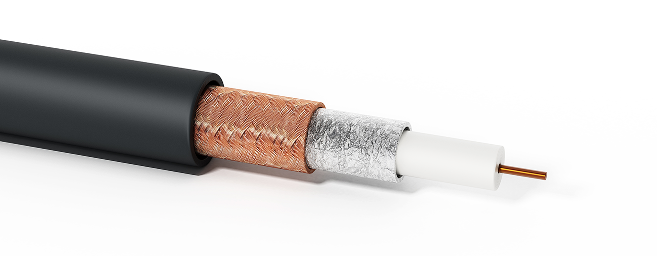
Coaxial Cable
Made of two conductors that share the same axis
Core conductor is made of solid or stranded copper wire
Enclosed by plastic insulation
Wire mesh wrapped around the plastic constitutes the second conductor
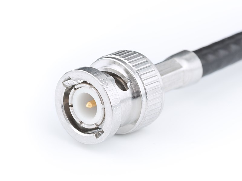
BNC Connector
Bayonet Neill-Concelman
Twist-and-lock mechanism
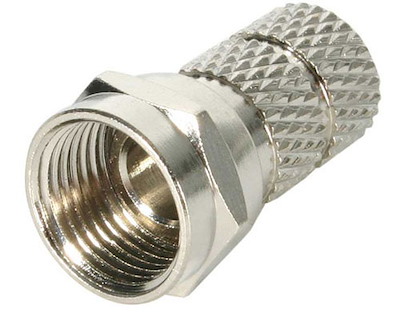
F-Type Connector
Secured by screwing them into place
Twinaxial Cable
Similar to coax but contains two inner conductors
Used for daatacenter interconnects working at 10 GbE
Maximum distance is up to about 5 meters for passive cable types and 10 for active cable types
Terminated using Direct Attach Copper (DAC) transceivers
ANSI/TIA/EIA 568 identifies the following locations of subsystem within a structured cabling system:
Work Area
Horizontal Cabling
Telecommunications Room
Backbone Cabling
Entrance Facilities/Demarc
Work Area
The space where user equipment is located and connected to the network, usually via a patch cable plugged into a wall port.
Horizontal Cabling
Connects user work areas to an IDF
When using copper cabling, IDF must be within 90m cabling distance of each wall port
Telecommunications Room
Room/closet that houses an intermediate distribution frame and networking equipment
The termination point for the horizontal cabling along with a connection to backbone cabling
Backbone Cabling
Connects IDFs to a main distribution frame
Entrance Facilities/Demarc
Marks the point at which external cabling is joined to internal cabling via the MDF
Entrance facilities are required to join the local exchange carrier’s network and for inter-building communications
The demarc point is where the access provider’s network terminates and the organization’s network begins.
T568A Wire Color
Pin 1 - Green/White
Pin 2 - Green
Pin 3 - Orange/White
Pin 4 - Blue
Pin 5 - Blue/White
Pin 6 - Orange
Pin 7 - Brown/White
Pin 8 - Brown
T568B Wire Color
Pin 1 - Orange/White
Pin 2 - Orange
Pin 3 - Green/White
Pin 4 - Blue
Pin 5 - Blue/White
Pin 6 - Green
Pin 7 - Brown/White
Pin 8 - Brown
Patch Panel
Has punch down blocks on one side and preterminated RJ45 modular ports on the other side
Allows incoming and outgoing connections to be reconfigured by changing the patch cable connections
Structured cabling running form the work area or forming a backbone is terminated at the back of the patch panel on the IDCs, either using T568A/T568B
Punch Down Tool
Terminates fixed cable
Cable crimper
Creates a patch cord
A single optical fiber is constructed from three elements
Core provides the transmission path, or waveguide, for the light signals.
Cladding reflects signals back into the waveguide as efficiently as possible
Buffer is a protective plastic coating
Fiber optic cables fall into two broad categories. What are those categories?
Single Mode Fiber (SMF)
Multimode Fiber (MMF)
Single Mode Fiber
Small core (8 to 10 microns)
Long wavelength
Uses a laser to generate a near infrared (1,310 or 1,550nm) signal
Can support data rates up to 100 Gbps
OS1/OS2 are two grades of SMF cable, with OS1 being for indoor use, and OS2 being for outdoor use
Multimode Fiber (MMF)
Larger core (62.5 or 50 microns)
Shorter wavelength light (850 or 1,300nm)
Uses less expensive optics and is less expensive than SMF
Does support such high signaling speeds or long distances
Most suitable for LANs
OM1/OM2
62.5 micron cable is OM1
50 micron cable is OM2
OM1/OM2 are mainly rated for application up to 1Gbps and use LED transmitters
OM3/OM4
Also 50 micron cable, but manufactured differently
Designed for use with 850nm vertical cavity surface emitting laser VCSEL
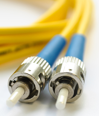
Straight Tip (ST)
Early bayonet-style connect that uses a push-and-twist locking mechanism
Mostly for multimode networks, but not widely used for Ethernet installations anymore
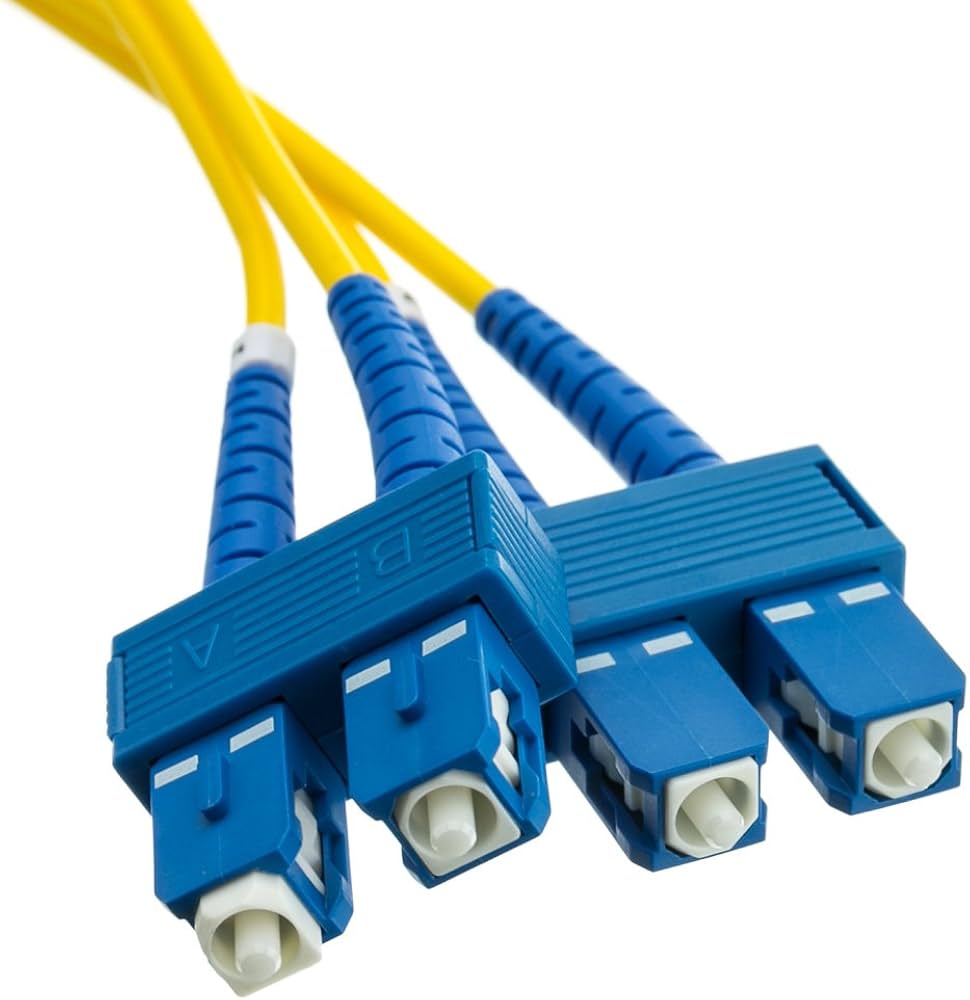
Subscriber Connector (SC)
Push/pull design, allowing for simple insertion and removal
Can be used for single or multimode
Commonly used for Gigabit Ethernet
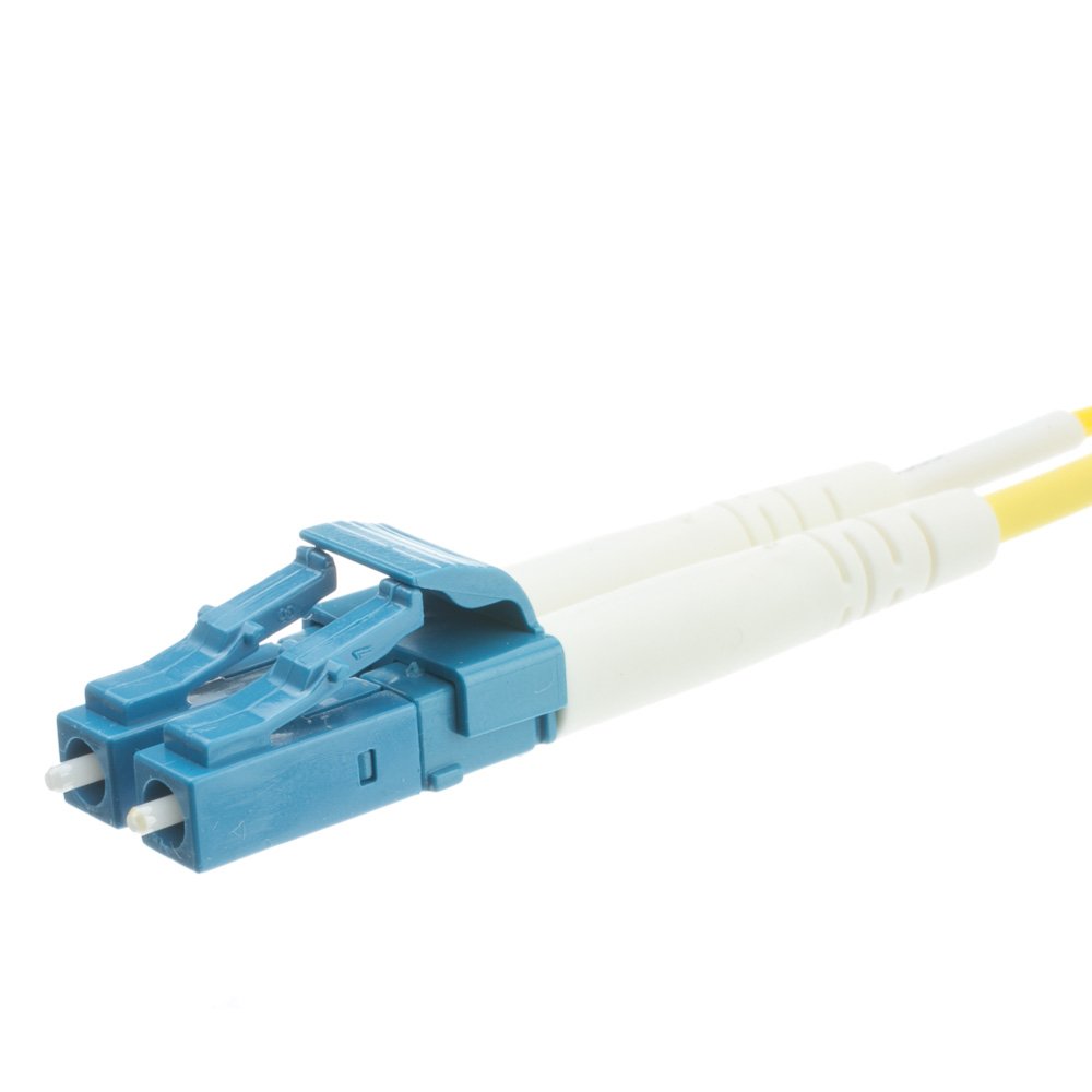
Local Connector (LC)
Also known as Lucent Connector
Small form factor with a tabbed push/pull design
Similar to SC, but the smaller size allows for higher port density
LC is widely adopted for Gigabit Ethernet and 10/40 GbE
Fiber Optic Cable Installation
Patch cables for fiber optic can come with same connector or a mix
Duplex patch cords must maintain the correct polarity, so that the Tx port on the transmitter is linked to the Rx port on the receiver and vice versa
TIA/EIA cabling standard sets out a system of A to B polarity
Each elements in the link must perform a crossover, and there must be an odd number of elements
Two finishing types for tip of ferrule
Ultra Physical Contact (UPC)
Angled Physical Contact (APC)
Ultra Physical Contact (UPC)
The faces of the connector and fiber tip are polished so that they curve slightly and fit together better
Angled Physical Contact (APC)
The faces are angled for an even tighter connection. APC cannot be mixed with PC or UPC
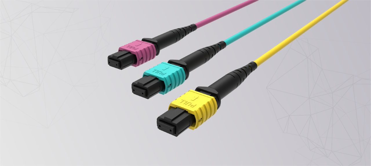
Multi-fiber push-on (MPO)
Allows for low-footprint backbone or trunk cabling
Bundles 12 or more strands terminated to a single compact ferrule
Mostly used to aggregate 10/25 Gbps lanes into 40/100/400 Gbps
Each lane normally requires two fiber strands
Bidirectional Transceivers
Support transmit and receive signals over the same strand of fiber
Uses WDM to transmit the Tx and Rx signals over slightly shifted wavelengths
Coarse Wavelength Multiplexing (CWDM)
Supports up to 16 wavelengths
Typically used to deploy four or eight bidirectional strands
Dense Wavelength Division Multiplexing (DWDM)
Provisions greater numbers of channels
Means that there is much less spacing between each channel and that it requires more precise and expensive lasers
Rack
Steel shelving system designed for standard-sized equipment
Using a rack allows equipment to be stored more securely and compactly
What environmental factors need to be monitored when it comes to equipment?
Temperature
Humidity
Electrical
Flooding
Temperature
High temperature will make it difficult for device and rack cooling systems to dissipate heat effectively. This increases the risk of overheating of components within the device chassis and consequent faults.
Humidity
More water vapor in the air risks condensation forming within a device chassis, leading to corrosion and short circuit faults. Conversely, very low humidity increases risks of static charges building up and damaging components.
Electrical
Computer systems need stable power supply, free from outages, voltage dips, and voltage spikes/surges. Sensors built into power distribution systems and backup battery systems can report deviations from a normal power supply.
Flooding
This may be natural or man made. Electrical systems need to be shut down immediately in the presence of any significant amount of water.
How is wattage calculated?
Volts * Current
How to calculate the maximum load for a rack?
Add up the watts used by each appliance power supply and divide by the circuit voltage
Power Distribution Unit (PDU)
Has circuitry to clean the power signals, provide protection against spikes, surges, and under-voltage events.
Class A Fire Extinguishers
Designed to combat fires fueled by ordinary combustible materials such as wood, paper, cloth, and plastics
Class C Fire Extinguishers
Gas-based extinguishing and can be used where the risk of electric shock makes other types unsuitable
Wet-pipe sprinklers
Work automatically
Triggered by heat
Discharge water
Constantly hold water at high pressure
Alternatives to wet-pipe systems
Dry-pipe
Pre-action
Halon
Clean agent
Dry-pipe
These are used in areas where freezing is possible; water only enters this part of the system if sprinklers are triggered elsewhere
Pre-action
System only fills with water when an alarm is triggered; it will then spray when the heat rises. This gives protection against accidental discharges and burst pipes and gives some time to contain the fire manually before the sprinkler operates.
Halon
Gas-based systems have the advantage of not short circuiting electrical systems and leaving no residue
Clean agent
Alternative to Halon. Known to not be damaging to the environment, it is also nontoxic to humans
Bit Rate (Bandwidth)
Amount of information that can be transmitted, measures in bits per second (bps).
Throughput
Average data transfer rate achieved over a period of time excluding encoding schemes, errors, and other losses incurred at the Physical and Data Link layers
Latency (Delay)
Another term used for speed in order to measure the speed at which packets are delivered.
Attenuation
Loss of signal strength, expressed in decibels
Interference
Anything that gets transmitted within or close to the channel that isn’t the intended signal
Cable Category Issues
Cat 5e supports Gigabit Ethernet and could still be an acceptable choice for providing network links for workstations, but most new installations and upgrades would now use Cat 6 or better.
Cat 6 can support 10 Gbps, but over a 55m maximum distance.
TIA/EIA recommends Cat 6A for healthcare facilities.
Cat 7 cable is always of a screened/shielded type and is rated for 10 Gbps applications up to 100m.
Cat 8 is intended for use in datacenters only for short patch cable runs.
Cable Tester
Reports detailed information on the physical and electrical properties of the cable
Can test and report on cable conditions, crosstalk, attenuation, noise, etc
Wire Map Tester
Used to detect improper termination issues
Wire map testers can identify the following problems:
Continuity (open)
Short
Incorrect pin-out/incorrect termination/mismatched standards
Reversed Pair
Crossed pair (TX/RX transposed)
Continuity (Open)
A conductor does not form a circuit because of cable damage or because the connector is not properly wired.
Short
Two conductors are joined at some point, usually because the insulating wire is damaged, or a connector is poorly wired.
Incorrect pin-out/incorrect termination/mismatched standards
The conductors in a pair have been wired to different terminals.
Crossed Pair
Conductors from one pair have been connected to pins belonging to a different pair.
Split Pair
Where both ends of a single wire in one pair are wired to terminals belonging to a different pair.
Tone Generator/Probe
Used to trace a cable from one end to the other.
Decibel (dB) loss
May mean that the link experiences signal degradation problems with high error rates and retransmissions resulting in reduced speeds and possibly loss of connectivity
Crosstalk
Indicates a problem with bad wiring, a bad connector, or improper termination
Higher values represent less noise
What are the various types of crosstalk that can be measured?
Near End (NEXT)
Attenuation to Crosstalk Ratio, Near End (ACRN)
Attenuation-to-Crosstalk Radio, Far End (ACRF)
Power Sum
Alien Crosstalk
Near End (NEXT)
This measures crosstalk on the receive pairs at the transmitter end and is usually caused by excessive untwisting of pairs or faulty bonding of shielded elements.
Attenuation to Crosstalk Ratio, Near End (ACRN)
This is the different between insertion loss and NEXT. ACR is equivalent to a signal-to-noise ration. A high value means that the signal is stronger than any noise present; a result closer to zero means the link is likely to be subject to high error rates.
Attenuation to Crosstalk Ratio, Far End (ACRF)
Far-end crosstalk (FEXT) is measured on the receive pairs at the recipient end. The difference between insertion loss and FEXT gives ACRF, which measures cable performance regardless of the actual link length.
Power Sum
Gigabit and 10 GbE Ethernet use all four pairs. Power sum crosstalk calculations confirm that a cable is suitable for this type of application. They are measured by energizing three of the four pairs in turn.
Alien Crosstalk
This is signal traffic from cables in close proximity that causes interference to a disturbed or victim cable. This is commonly caused by cinching a cable bundle with ties to tightly and by poorly terminated cabling.
Cable Troubleshooting Strategies
Physical inspection
Reseat the cable
Verify drivers
Physical Inspection
Check the cable for any visible damage such as cuts, kinks, or severe bends.
Ensure that the connectors are not damaged and are securely plugged into the network device and the computer.
Reseat the Cable
Unplug the cable from both ends and then plug it back in. This can resolve loose connection issues.
Verify Drivers
If the problem persists, the issue could be the drivers or a physical problem with the network adapter.
Open Device Manager on your computer, find your network adapter in the list, and check if it’s working properly.
If it is not working properly, you may need to update the drivers or replace the network adapter.