Radiographic Procedures 2 (155) Mobile Radiography
1/33
Earn XP
Description and Tags
Chapters 20 Mobile Radiography
Name | Mastery | Learn | Test | Matching | Spaced | Call with Kai |
|---|
No analytics yet
Send a link to your students to track their progress
34 Terms
Mobile radiography
use of transportable x-ray equipment to bring imaging services to the patient
commonly performed in:
patient rooms
ER
ICU
OR
PACU
nursery and NICU
Mobile units
not as sophisticated as stationary units
typical unit has controls for setting kVp and mAs
mAs controls automatically adjusts mA and time
typical mAs range: 0.04-320
kVp: 40-130
power varies between 15-25 kW
anatomic programs (APRs)
Digital Mobile units
mobile units with direct digital capability
acquire image within seconds after exposure
uses a flat-panel detector
wirelessly transfer images to PACS
lower radiation doses possible
Technical considerations
grid, anode heel effect, source-to-image receptor distance (SID)
exposure technique charts are essential to optimize exams
Grid considerations
sensitivity of CR imaging plates to scatter radiation leads to image degradation
optimum performance:
level: use of grid on unstable surface may cause “off level” grid cutoff
centered to CR: midline of a grid more than 1-1½ inches off transversely from the CR causes “off level” grid cutoff
used at recommended focal distnace or radius: exposures outside the recommended focal range may produce cuttoff on the lateral margins
Anode heel effect
causes decreased image density under the anode side of the x-ray tube
more pronounced with:
short SID
larger field sizes
small anode angles
short SID and large field sizes are common in mobile
proper placement of anode-cathode axis with anatomy is essential
Source to image distance (SID)
should be maintained at 40 inches (102 cm)
standardized distance ensures consistent images
longer SIDs:
requires increased mAs resulting in longer exposure times
increased risk of motion artifacts
Radiation safety in mobile x-ray
produces some of the highest occupational radiation exposure to radiographers
protection for self, patient, and other personnel:
wearing a lead apron
standing as far away from patient, tube, and beam as possible
recommended minimal distance is 6ft
standing at a right angle (90 degrees) to the primary beam
Mobile x-ray in isolation
two types of patients in isolation:
those who have contagious infectious microorganisms
those who must be protected from exposire to infectious microorganisms (reverse isolation)
wear all required protective apparel for specific situation
Equipment used in mobile
IR
grid
protective covers
tape
caliper
markers
positioning blocks
lead
requisition
Initial mobile x-ray procedure
preliminary steps for the radiographer prior to performing mobile radiography:
announce presence to nursing staff
ask for assistance if needed
confirm patient identity
introduce yourself to patient and family
explain the examination
observe medical equipment in room and move if necessary
ask family members and visitors to step out of the room
Mobile unit placement
supine position: middle of bed
seated upright position: foot of the bed
lateral and decubitus positions: parallel or perpendicular to bed
Patient considerations
assessment of patient condition
altertness
respiration
ability to cooperate
limitations to procedure
patient mobility
never move a patient or part without assessment of ability to move or ability to tolerate movement
check with nursing staff or physician to obtain assistance and permission to move a part that has had surgery or is fractured
inappropriate movement can further injure the patient
fractures
various fractures and fracture types
patient ability to assist
key is to be cautious and gentle for both patient safety and comfort
work in accordance with the patient’s condition and pain tolerance
interfering devices
orthopedic beds, fracture frames, tube, and wiring produce artifacts
some objects can be moved and some require procedure modification to obtain the image
some procedures have to be performed with the object in the image
get assistance if unsure an object can be moved
positioning and aspesis
warn patietn of potential discomfort of IR
IR can damage skin of older patient
protect Ir from contamination by use of cover
disinfect IR for asepsis and infection control
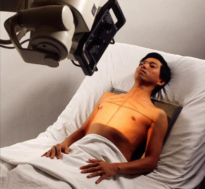
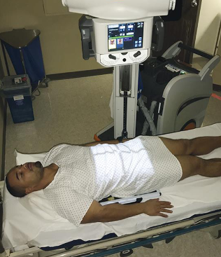
AP chest
patient position:
dependent on condition
seated upright, semi upright, or supine
greatest upright angle the patient can tolerate, whenever possible
use the supine position for critically ill or injured patients
part position:
center MSP to IR
top of IR 2 inches above relaxed shoulders
internally rotate patient’s arms (if not contraindicated)
no leaning or rotation of upper torso
CR:
perpendicular to long aixs of sternum and center of IR
enters approximately 3 inches below jugular notch at level of T7
respiration:
inspiration, unless otherwise requested
if respiration assistance is provided, watch patient’s chest to determine inspiratory phase
collimation:
14 × 17 in
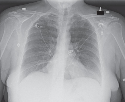
AP chest image criteria
structures shown:
anatomy of thorax:
heart
trachea
ribs
diaphragmatic domes
entire lung fields
vascular markings
evaluation criteria:
no motion; well-defined diaphragmatic domes and lung fields
lung fields in their entirety including costophrenic angles
pleural markings
ribs and thoracic intervertebral disk spaces faintly visible through heart shadow
no rotation; medial portion of clavicles and alteral border of ribs equidistant from vertebral column
AP/PA chest lateral decubitus
patient position:
right or left lateral recumbent
affected side down for fluid levels
unaffected side down for air levels
remain for 5 minutes for air/fluid levels
knees flexed
place firm support under body to elevate 2-3 inches
raise arms over head or out of anatomy of interest
protect patient from rolling off bed
part position:
ensure lateral position without rotation
IR behind patient and below support
top of IR 2 inches above relaxed shoulders
CR:
horizontal and perpendicular to IR
enters approx. 3 inches below jugular notch at level of T7
respiration:
inspiration unless otherwise requested
collimation:
14 × 17 in
AP/PA chest lateral decubitus image criteria
structures shown:
anatomy of thorax
air or fluid levels
evaluation criteria:
no motion or rotation
affected side in its entirety
upper lung for free air
lower lung for fluid
arms out of region of interest
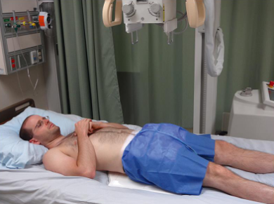
AP abdomen
patient position:
supine
adjust bed in horizontal position
part position:
place grid under body centered to MSP and level of iliac crests
for upper abdomen, center grid 2 inches above iliac crests
use draw sheet to roll patient and as barrier between skin and IR
ensure grid does not tip to prevent cutoff
align shoulders and hips in same plane
place arms out of anatomy of interest
CR:
perpendicular to center of grid
enters at MSP at level of iliac crests or 10th rib laterally
respiration:
expiration
Collimation:
14 × 17 inches
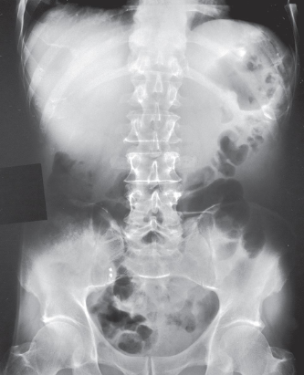
AP abdomen image criteria
structures shown:
inferior margin of liver
spleen
kidneys
psoas muscles
calcifications
evidence of tumor masses
size and shape of liver if upper abdomen and diaphragm included
evaluation criteria:
no motion
outlines of abdominal viscera
abdominal region including ppubic symphysis or diaphragm
vertebral cloumn centered
psoas muscles, lower margin of liver, and kidney margins
no rotation
symmetric appearance of vertebral column and iliac wings
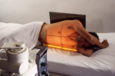
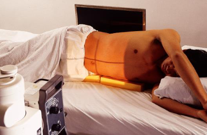
AP/PA abdomen left lateral decubitus
patient position:
left lateral recumbent position
flex knees for stability
place firm support under patient to elevate body
raise both arms out of anatomy of interest
ensure patient cannot roll out of bed
leave in position for 5 minutes to allow air to rise and fluid to settle
part position:
true lateral without rotation
place vertical grid centered at 2 inches above iliac crests to demonstrate diaphragm
ensure patient has been in position for at least 5 minutes to allow air to rise and fluid to settle
CR:
horizontal and perpendicular to center of grid
enters at MSP at level 2 inches above iliac crests
respiration:
expiration
collimation:
14 × 17 inches
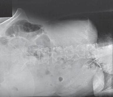
AP/PA abdomen left lateral decubitus image criteria
structures shown:
air or fluid levels
right border of the abdominal region must be visualized
evaluation criteria:
no motion
well-defined diaphragm and abdominal viscera
air or fluid levels
right and elft abdominal wall and flank structures
no rotation
symmetric appearance of vertebral column and iliac wings
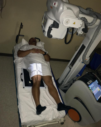
AP pelvis
patient position:
supine
adjust bed to horizontal
move arms out of anatomy of interest
part position:
place grid under pelvis
centered to MSP at level midway between ASIS and pubic symphysis
no rotation of pelvis
rotate legs medially approx. 15 degrees, when not contraindicated
CR:
perpendicular to IR center
enters patient at MSP at 2 inches above pubic symphysis and 2 inches below ASIS
respiration:
suspended
collimation:
14 × 17 inches
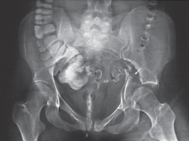
AP pelvis image criteria
structures shown:
pelvis with both hip bones
sacrum and coccyx
proximal femora including head, neck, and trochanters
evaluation criteria:
entire pelvis, including proximal femora and hip bones
no rotation
symmetric appearance of iliac wings and obturator foramina
femoral necks no foreshortened
greater trochanters in profile
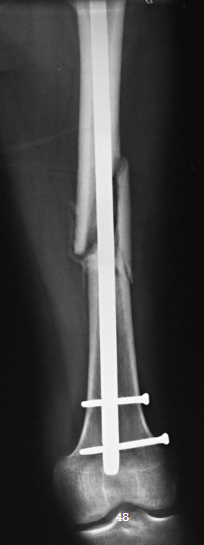
AP femur
patient position:
supine
patient generally has limited mobility
part position:
carefully place grid lengthwise under femur
centered to midline of femur
distal end of grid low enough to include fracture site, pathology, and knee joint
ensure grid aligned parallel with CR and femoral condyles
CR:
perpendicular to long axis of femur and center of grid
CR and grid must be aligned to prevent cutoff
respiration:
suspended
collimation:
top of ASIS for hip, bottom at tibial tuberosity for knee, 1 inch on side of the shadow of the femur, and 17 inches in length
AP femur image criteria
structures shown:
distal 2/3 of femur
knee joint
evaluation criteria:
most of femur including knee joint for distal
no rotation of knee
adequate penetration
orthopedic appliance in its entirety
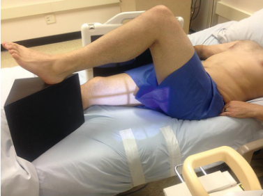
Lateral femur
patient position:
dorsal decubitus
part position:
use either mediolateral or lateromedial projection
mediolateral projection preferred because it provides more visualization of proximal femur
mediolateral projection:
place vertical grid along lateral aspect of femur
distal edge of grid low enough to include knee joint
support unaffected leg with patient’s support or support block
elevate unaffected leg until femur is near vertical
lateromedial projection:
place vertical grid along medial aspect of femur (between patient’s legs)
make sure knee joint is included
ensure grid is perpendicular to the epicondylar plane
CR:
perpendicular to long axis of femur
centered to femur
CR and grid must be aligned to prevent cutoff
respiration:
suspended
collimation:
radiation field at top of ASIS for hip, bottom at tibial tuberosity for knee, 1 inch on side of the shadow of the femur, and 17 inches in length
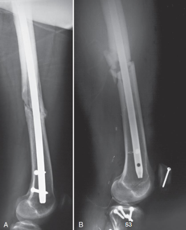
Lateral femur image criteria
structures shown:
distal 2/3 of femur
knee joint
no superimposition of opposite thigh
evaluation criteria:
most of femur with knee joint
patella in profile
superimposition of femoral condyles
oppposite femur and soft tissue out of area of interest
adequate penetration of proximal femur
orthopedic appliance if present
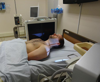
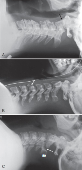
Lateral C-spine
patient position:
right or left dorsal decubitus
arms extended alongside of body
do not remove any immobilization device without physician consent
part position:
no rotation of upper torso, cervical spine, and head
grid lengthwise on right or left side, parallel to neck
top of grip approx. 1 inch above external acoustic meatus (EAM) and centered to C4
raise chin slightly, if not contraindicated
relax shoulders and reach for feet, if possible
CR:
horizontal and perpendicular to center of grid
enters level of C4
increased OID; SID of 60-72 inches recommended to show C7
respiration:
full expiration for depression of shoulders
collimation:
radiation feild at top of ear attachment (TEA), bottom to jugular notch, and 1 inch on the sides of the neck
Lateral C-spine image criteria
structures shown:
seven cervical vertebrae
base of skull
soft tissue of neck
evaluation criteria:
all seven cervical vertebrae
neck extended when possible, so mandibular rami are no superimposing C1 or C2
C4 centered
superimposed posterior margins of each vertebral body
Best practices
speed
knowledge
positioning accuracy
practice standard precautions
immobilizations
equipment
attention to detail
attention to department protocol and scope of practice
professionalism
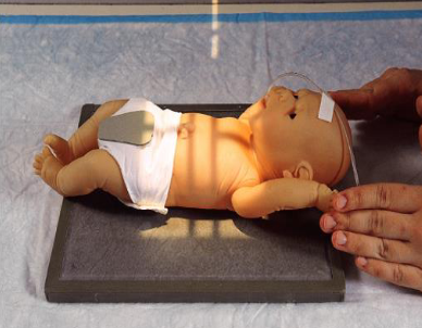
AP chest/abdomen neonate
infant is supine
move arms out of anatomy of interest
bring legs down
leave head rotated to avoid advancing endotracheal tube too far
collimate closely
shield gonads
CR is perpendicular to IR
infant respirations are rapid
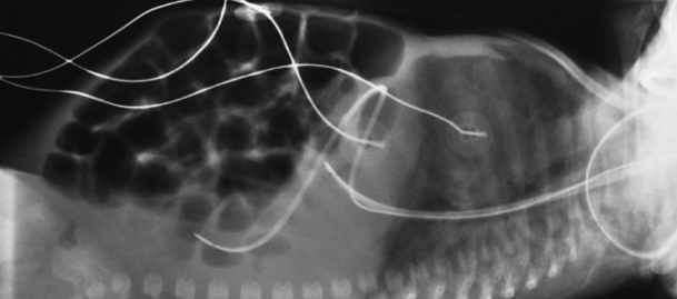
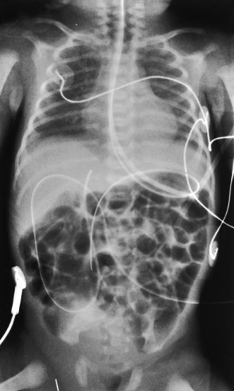
AP chest/abdomen neonate image
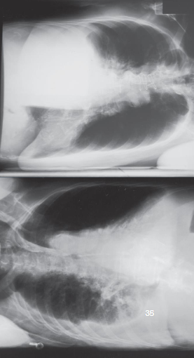
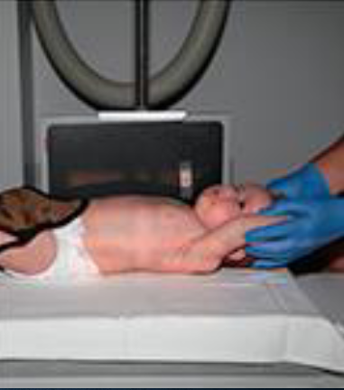
Lateral chest/abdomen neonate
obtained using dorsal decubitus position
elevate infant on blcok wrapped in soft cover
place IR lengthwise and vertical beside infant and immobilize
center infant’s chest and abdomen to IR
have nurse hold arms and legs out of collimated field
CR is horizontal and perpendicular to IR
enters on MCP
exposure made on inspiration
Lateral chest/abdomen neonate image