Airframe Block 9 (Landing Gear Systems)
1/96
Earn XP
Description and Tags
FAA Test Guide Questions
Name | Mastery | Learn | Test | Matching | Spaced |
|---|
No study sessions yet.
97 Terms
8327. On all aircraft equipped with retractable landing gear, some means must be provided to
A—retract and extend the landing gear if the normal operating mechanism fails.
B—extend the landing gear if the normal operating mechanism fails.
C—prevent the throttle from being reduced below a safe power setting while the landing gear is retracted.
(B) All aircraft equipped with retractable landing gear must incorporate some means by which the gear may be extended if the normal operating mechanism fails. (AM. II.E.K2) — AC 43.13-1
8333. When an air/oil type of landing gear shock strut is used, the initial shock of landing is cushioned by
A—compression of the air charge.
B—the fluid being forced through a metered opening.
C—compression of the fluid.
(B) The initial landing impact is cushioned in an air-oil shock strut by the fluid being forced from one chamber to another through a metered opening. (AM.II.E.K2) — FAA-H-8083-31
8336. The purpose of a sequence valve in a hydraulic retractable landing gear system is to
A—prevent heavy landing gear from falling too rapidly upon extension.
B—provide a means of disconnecting the normal source of hydraulic power and connecting the emergency source of power.
C—ensure operation of the landing gear and gear doors in the proper order.
(C) A sequence valve is installed in a hydraulic landing gear system to ensure that the landing gear doors are fully open before the landing gear is either retracted or extended. (AM.II.E.K2) — FAA-H-8083-31
8344. If the extended longitudinal axis of the main landing gear wheel assemblies intersects aft of the aircraft, the wheels can be termed as having
A—toe-out.
B—toe-in.
C—negative camber.
(A) If lines drawn through the center of each of the wheels of an aircraft landing gear cross behind the wheels, the landing gear has toe-out. The landing gear will tend to spread out as the aircraft rolls forward. (AM.II.E.K2) — FAA-H-8083-31
8373. An electric motor used to raise and lower a landing gear would most likely be a
A—shunt field series-wound motor.
B—split field shunt-wound motor.
C—split field series-wound motor.
(C) Aircraft landing gear that are retracted and lowered with an electric motor use a series-wound motor because of its high starting torque and a split-field motor to both raise and lower the gear. (AM.II.E.K2) — FAA-H-8083-31
8375. Nose gear centering cams are used in many retractable landing gear systems. The primary purpose of the centering device is to
A—align the nosewheel prior to touchdown.
B—engage the nosewheel steering.
C—center the nosewheel before it enters the wheel well.
(C) Many retractable nose gears use a centering cam to center the nosewheel when all the weight is off of the shock strut. The centering cam ensures that the wheel is positioned so it will fit into the wheel well properly. (AM. II.E.K2) — FAA-H-8083-31
8308. To prevent a very rapid extension of an oleo shock strut after initial compression resulting from landing impact,
A—various types of valves or orifices are used which restrict the reverse fluid flow.
B—the metering pin gradually reduces the size of the orifice as the shock strut extends.
C—the air is forced through a restricted orifice in the reverse direction.
(A) Various types of valves and orifices are used inside an oleo strut to prevent a rapid extension of the strut after the initial landing impact has been absorbed. (AM.II.E.K3) — FAA-H-8083-31
8329. What is the purpose of the torque links attached to the cylinder and piston of a landing gear oleo strut?
A—Limit compression stroke.
B—Hold the strut in place.
C—Maintain correct wheel alignment
(C) The torque links that attach the piston to the cylinder of a landing gear oleo strut maintain the correct wheel alignment. (AM.II.E.K3) — FAA-H-8083-31
8335. A sleeve, spacer, or bumper ring is incorporated in a landing gear oleo shock strut to
A—limit the extension of the torque arm.
B—limit the extension stroke.
C—reduce the rebound effect.
(B) A sleeve, spacer, or bumper ring is incorporated inside an air-oil shock strut to limit its extension stroke. (AM. II.E.K3) — FAA-H-8083-31
8340. When servicing an air/oil shock strut with MIL-5606 the strut should be
A—collapsed and fluid added at the filler opening.
B—fully extended and fluid added at the filler opening.
C—partially extended and fluid added at the filler opening.
(A) To service an air-oil shock strut, bleed all of the air out to collapse the strut, and remove the strut filler valve. Completely fill the collapsed strut with MIL-H-5606 fluid, and exercise the strut by moving the piston into and out of the cylinder to work all of the air out of the strut. Replace the filler valve and, with the weight of the aircraft on the wheel, fill the strut with compressed air or nitrogen until the strut extends to the correct height. (AM.II.E.K3) — FAA-H-8083-31
8341. Instructions concerning the type of fluid and amount of air pressure to be put in a shock strut are found
A—on the airplane data plate.
B—in the aircraft operations limitations.
C—in the aircraft manufacturer’s service manual.
(C) The type of fluid and the recommended air pressure to be used in an aircraft shock strut is found in the aircraft manufacturer’s service manual. (AM.II.E.K3) — FAA-H8083-31
8346. If an aircraft shock strut (air/oil type) bottoms upon initial landing contact, but functions correctly during taxi, the most probable cause is
A—low fluid.
B—low air charge.
C—a restricted metering pin orifice.
(A) If an aircraft shock absorber bottoms out on initial landing contact but functions properly during taxiing, the fluid supply is probably low but the air charge is proper. (AM. II.E.K3) — FAA-H-8083-31
8347. What is the function of a cam incorporated in a nose gear shock strut?
A—Provides an internal shimmy damper.
B—Straightens the nosewheel.
C—Provides steering of aircraft during ground operation.
(B) Many retractable landing gears use a centering cam to center the nosewheel when all the weight is off of the shock strut. The centering cam ensures that the wheel is positioned so it will fit into the wheel well properly when it is retracted. (AM.II.E.K3) — FAA-H-8083-31
8348. Extension of an oleo shock strut is measured to determine the
A—amount of oil in the strut.
B—physical condition of the strut itself.
C—proper operating position of the strut.
(C) The amount of extension of an oleo strut is measured to determine the proper amount of air in the strut. This is undoubtedly what is meant in this question by the proper “operating position” of the strut. (AM.II.E.K3) — FAA-H8083-31
8350. If a shock strut bottoms after it has been properly serviced, the
A—strut should be disassembled and the metering pin orifice plate replaced.
B—air pressure should be increased.
C—strut should be removed, disassembled, and inspected.
(C) If a shock strut bottoms after it has been properly serviced with both oil and air, it should be removed from the aircraft, disassembled, and inspected to find the problem. (AM. II.E.K3) — FAA-H-8083-31
8354. What should be checked when a shock strut bottoms during a landing?
A—Air pressure.
B—Packing seals for correct installation.
C—Fluid level.
(C) If a shock strut bottoms during landing, the fluid is probably low. Transfer of the fluid from one chamber to another cushions the impact of landing, whereas the air pressure cushions the shocks produced when the aircraft is taxiing. (AM.II.E.K3) — FAA-H-8083-31
8358. The hydraulic packing seals used in a landing gear shock strut are
A—generally designed to be compatible with more than one type of fluid.
B—kept from direct contact with fluid by teflon or nylon backup rings.
C—used only with a specific type of fluid.
(C) The seals used in a landing gear shock strut are made of a material that is compatible only with the type of fluid that is used in the strut. When replacing the seals, use only the seal having the correct part number and a current cure date. (AM.II.E.K3) — FAA-H-8083-31
8368. When servicing an empty shock strut with fluid, the strut should be completely compressed and extended several times to ensure
A—the piston rod and wiper are lubricated with hydraulic fluid.
B—all excess hydraulic fluid is forced out of the strut.
C—proper packing ring seating and removal of air bubbles.
(C) When a shock strut has been filled with fluid, it should be extended and compressed at least twice to be sure that all the packing rings are properly seated and all the air is worked out of the fluid. (AM.II.E.K3) — FAA-H-8083-31
8369. In shock struts, chevron seals are used to
A—absorb bottoming effect.
B—prevent oil from escaping.
C—serve as a bearing surface.
(B) The chevron seals installed in an oleo shock strut prevent oil from escaping from the strut. (AM.II.E.K3) — FAA-H8083-31
8370. On most aircraft, the oil level of an air and oil shock strut is checked by
A—removing the oil filler plug and inserting a gauge.
B—measuring the length of the strut extension with a certain air pressure in the strut.
C—releasing the air and seeing that the oil is to the level of the filler plug.
(C) The oil level in an oleo shock strut is checked by releasing the air from the strut and filling the strut with oil to the level of the filler plug. (AM.II.E.K3) — FAA-H-8083-31
8328. An automatic damping action occurs at the steering damper if for any reason the flow of high-pressure fluid is removed from the
A—outlet of the steering damper.
B—inlet of the steering damper.
C—replenishing check valve.
(B) A steering damper is a hydraulically operated device that accomplishes the functions of steering and eliminating shimmying. The steering damper automatically reverts to damping when, for any reason, the flow of high-pressure fluid is removed from its inlet. (AM.II.E.K5) — FAA-H8083-31
8313. What action should be taken whenever maintenance is performed that will affect the landing gear system performance?
A—A test flight should be performed to conduct an operational check.
B—A technician with an inspection authorization should perform a visual inspection.
C—The aircraft should be placed on jacks and a retraction test should be performed.
(C) Any maintenance done to an aircraft landing gear that could affect its ability to retract and extend should be followed by a retraction test with the aircraft on jacks. (AM. II.E.K6) — FAA-H-8083-31
8372. When will a continuous horn provide a warning in the flight deck?
A—When the throttle is retarded and gear is not down and locked.
B—When the throttle is advanced and gear is down and locked.
C—When the throttle is retarded and gear is down and locked.
(A) A landing gear warning system will cause a warning horn in the flight deck to sound when the throttle is pulled back, as it would be for landing if the landing gears are not all down and locked. (AM.II.E.K6) — FAA-H-8083-31
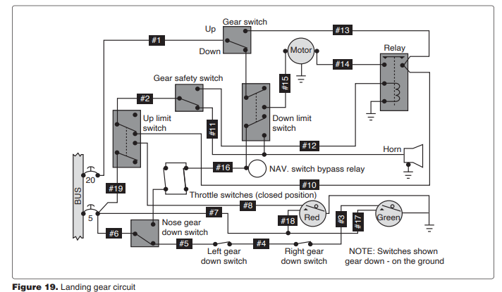
8951. (Refer to Figure 19.) What is the indication of the red landing gear position light under the following conditions? Aircraft on jacks. Landing gear in transit. Warning horn sounding.
A—extinguished.
B—flashing.
C—illuminated.
(A) When the aircraft is on jacks, the gear safety switch is changed from that in Figure 19.
The landing gear is in transit, causing the position of the nose-gear-down switch and the down-limit switch to be changed.
The warning horn is sounding. Current is flowing from the 5-amp circuit breaker, through wire #6, the changed position of the nose-gear-down switch, one or both of the throttle switches, and the changed down-limit switch to the horn.
The landing gear has not yet reached its up-and-locked position, so the up-limit switch is in the position shown. Until the gear reaches its up-and-locked position, there is no power to the red landing gear position light, and the light remains extinguished. (AM.II.E.K6) — FAA-H-8083- 31

8952. (Refer to Figure 19). Which repair should be made if the gear switch was placed in UP position and the gear does not retract?
A—Replace electrical wire No. 15.
B—Replace the down limit switch.
C—Replace electrical wire No. 12.
(C) If the landing gear does not retract when the weight is off the landing gear and the gear switch is placed in the UP position, wire 12 could be faulty and need to be replaced.
Current flows from the bus through the 20-amp circuit breaker, through wire 1 to the gear switch in the UP position, through wires 13 and 10 to the up-limit switch in the position shown, through the gear safety (squat) switch whose position is changed, through wire 12 to the relay coil. When the relay is energized, current flows through its contacts and wire 14 to the gear motor to retract the landing gear. (AM.II.E.K6) — FAA-H-8083-31
8953. Which of the following conditions is most likely to cause the landing gear warning signal to sound?
A—Landing gear locked down and throttle advanced.
B—Landing gear locked down and throttle retarded.
C—Landing gear not locked down and throttle retarded.
(C) The landing gear warning horn will sound if the landing gears are not all down and locked, and the throttle is retarded to reduce power for landing. (AM.II.E.K6) — FAA-H-8083-31
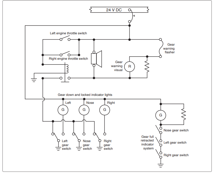
8954. (Refer to Figure 20.) What will illuminate the amber indicator light?
A—Closing the nosewheel gear full retract switch.
B—Retarding one throttle and closing the left wheel gear locked down switch.
C—Closing the nose, left and right wheel gear full retract switches.
(C) In order for the amber indicator light to illuminate, all three of the landing gears must be in their up-and-locked position. The full retracted switches for the nosewheel, left wheel, and right wheel must all be closed. (AM.II.E.K6) — FAA-H-8083-31

8955. (Refer to Figure 20.) What is the minimum circumstance that will cause the landing gear warning horn to indicate an unsafe condition?
A—All gears up and one throttle retarded.
B—Any gear up and both throttles retarded.
C—Any gear not down and locked, and one throttle retarded.
(C) The landing gear warning horn (aural warning) will sound anytime either throttle is retarded and any one of the landing gears is not down and locked. (AM.II.E.K6) — FAA-H-8083-31
8956. Where is the landing gear safety switch usually located?
A—On the main gear shock strut.
B—On the landing gear drag brace.
C—On the pilot’s control pedestal.
(A) The landing gear safety switch, or squat switch, is usually located on one of the main landing-gear shock struts. (AM. II.E.K6) — FAA-H-8083-31
8957. What safety device is actuated by the compression and extension of a landing gear strut?
A—Uplock switch.
B—Downlock switch.
C—Ground safety switch.
(C) The ground safety switch (squat switch), is actuated by the compression of the landing gear oleo strut. The ground safety switch prevents the landing gear from retracting when the weight of the aircraft is on the landing gear. (AM.II.E.K6) — AC 43.13-1B
8958. Which repair would require a landing gear retraction test?
A—Landing gear safety switch.
B—Red warning light bulb.
C—Gear downlock microswitch.
(C) The replacement of a landing gear downlock microswitch would require a retraction test in which the airplane is put on jacks and the landing gear is retracted and extended. This type of test is required anytime any change or adjustment is made that could affect the operation of the retracting mechanism. (AM.II.E.K6) — FAA-H-8083-31
8959. Landing gear warning systems usually provide which of the following indications?
A—Red light for unsafe gear; green light for gear up.
B—Green light for gear up and down; red light for unsafe gear.
C—Red light for unsafe gear; green light for gear down; no light for gear up.
(C) Some landing gear systems indicate in the manner shown here. A red light shows an unsafe condition and a green light shows when each gear is down and locked. There is no light to show when the landing gear is up and locked. (AM.II.E.K6) — FAA-H-8083-31
8960. In most modern hydraulically actuated landing gear systems, the order of gear and fairing door operation is controlled by
A—sequence valves.
B—shuttle valves.
C—microswitches.
(A) Hydraulically actuated landing gear systems that have hydraulically actuated wheel-well doors, control the operating sequence of the doors and the landing gear by the use of sequence valves. These valves prevent the landing gear from retracting while the doors are closed. (AM.II.E.K6) — FAA-H-8083-31
8961. What landing gear warning device(s) is/are incorporated on retractable landing gear aircraft?
A—A visual indicator showing gear position.
B—A light which comes on when the gear is fully down and locked.
C—A horn or other aural device and a red warning light.
(C) All retractable-landing-gear aircraft must have some type of device to warn the pilot if the landing gear is not down and locked when the throttles are retarded for landing. All of the devices listed in the alternatives for this question are indicators except the horn or other aural device and a red warning light. (AM.II.E.K6) — FAA-H-8083-31
8962. When a landing gear safety switch on a main gear strut closes at liftoff, which system is deactivated?
A—Landing gear position system.
B—Antiskid system.
C—Aural warning system.
(B) When the landing gear strut indicates that the weight is off of the landing gear, the safety switch deactivates the antiskid system. An antiskid system has a provision that prevents the brakes from being applied, regardless of the position of the brake pedal, until weight is on the landing gear. (AM.II.E.K6) — FAA-H-8083-31
9039. An amber light in a gear position indicator system typically indicates what condition?
A—At least one gear is in transition.
B—The airspeed is too high for selecting gear down.
C—All landing gear are down and locked.
(A) An amber in-transit light is typically used to indicate that the landing gear is in transition. In older aircraft, an amber light may be used to indicate that the gear is up. (AM. II.E.K6) — FAA-H-8083-31
8307. In brake service work, the term “bleeding brakes” is the process of
A—withdrawing air only from the system.
B—withdrawing fluid from the system for the purpose of removing air that has entered the system.
C—replacing small amounts of fluid in reservoir.
(B) Bleeding the brakes means removing any fluid from the system that has air trapped in it. (AM.II.E.K7) — FAA-H8083-31
8310. Aside from an external leak in the line, what will cause parking brakes to continually bleed off pressure?
A—An internal leak in the master cylinder.
B—Insufficient hydraulic fluid in the reservoir.
C—Glazed brake linings.
(A) An internal leak in a brake master cylinder will cause the brakes to creep to the OFF position after the parking brake has been set. (AM.II.E.K7) — FAA-H-8083-31
8315. The braking action of a Cleveland disc brake is accomplished by compressing a rotating brake disc between two opposite brake linings. How is equal pressure on both sides of the rotating disc assured?
A—By allowing the brake rotor to float to automatically equalize as pressure is applied to the rotor.
B—By allowing the caliper to float to automatically equalize as pressure is applied to the rotor.
C—By allowing the brake linings to automatically equalize as pressure is applied to the rotor
(B) The disc in Cleveland single-disc brakes is rigidly attached to the wheel and rotates between linings that are riveted to the backplate and the pressure plate in the caliper. The caliper is free to float laterally on two anchor bolts that ride in holes in the torque plate. When the brakes are applied, the caliper moves out on the anchor bolts to provide equal pressure on both sides of the rotating disc. (AM.II.E.K7) — FAA-H-8083-31
8316. If it is determined that spongy brake action is not caused by air in the brake system, what is the next most likely cause?
A—Worn brake lining.
B—Internal leakage in the master cylinder.
C—Deteriorated flexible hoses.
(C) Spongy brake action not caused by air in the system may be caused by deteriorated flexible hoses. The hose may expand as the pressure is built up. (AM.II.E.K7) — FAAH-8083-31
8317. Many brake types can be adapted to operate mechanically or hydraulically. Which type is not adaptable to mechanical operation?
A—Single-disc spot type.
B—Single-servo type.
C—Expander-tube type.
(C) Expander-tube brakes cannot be adapted for mechanical operation. They depend upon fluid inside the tube for their application. (AM.II.E.K7) — FAA-H-8083-31
8318. A brake debooster valve is installed in systems where the high pressure of the hydraulic system (3,000 psi) is used to operate brakes
A—that are designed to work with lower pressure.
B—that are used in conjunction with an antiskid system.
C—that are used on aircraft having high landing speeds.
(A) Brake deboosters are installed between the power brake control valve and the wheel cylinders of aircraft that are equipped with power brakes that use pressure supplied by the aircraft main hydraulic system. System pressure is too high for smooth brake application, so the debooster decreases the pressure and increases the flow of fluid to the brakes so they will apply smoothly and release quickly. (AM.II.E.K7) — FAA-H-8083-31
8320. When bleeding aircraft brakes, one of the indications that the air has been purged from the system is
A—partial brake pedal travel.
B—full brake pedal travel.
C—firm brake pedals.
(C) Brakes are bled to remove all air from the fluid. When all of the air has been removed, the pedal will have a firm, rather than spongy, feel. (AM.II.E.K7) — FAA-H-8083-31
8338. Which statement is true with respect to an aircraft equipped with hydraulically operated multiple-disc type brake assemblies?
A—There are no minimum or maximum disc clearance checks required due to the use of selfcompensating cylinder assemblies.
B—Do not set parking brake when brakes are hot.
C—No parking brake provisions are possible for this type of brake assembly.
(B) Do not set the parking brakes on an aircraft equipped with multiple-disc brakes when the brakes are hot. Setting the parking brake on a hot brake will usually cause the brake discs to warp. (AM.II.E.K7) — FAA-H-8083-31
8356. The left brake is dragging excessively on an airplane on which no recent brake service work has been performed. The most probable cause is
A—foreign particles stuck in the master cylinder compensating port.
B—excessively worn brake linings.
C—low fluid supply in the brake system reservoir.
(A) The compensating port in a brake master cylinder must be open to vent the fluid in the brake line to the reservoir. If the port is plugged with a piece of foreign matter, the brake cannot release when pressure is removed from the pedal. The brake will drag. (AM.II.E.K7) — FAA-H-8083-31
8934. An antiskid system is designed to
A—solely sense the deceleration rate of every main landing gear wheel.
B—release then reapply pressure at a slightly lower value when a skid is detected only.
C—sense the deceleration rate of every main landing gear wheel and release then reapply pressure at a slightly lower value when a skid is detected.
(C) Antiskid generators are mounted in the wheel hubs, and they produce a signal whose frequency is proportional to the wheel rotational speed. This signal is sent into a computer where its rate of frequency change is compared with an allowable rate of change. If the rate is too fast, it signals that a skid is impending. (AM.II.E.K8) — FAA-H-8083-31
8935. In a brake antiskid system, when an approaching skid is sensed, an electrical signal is sent to the skid control valve which
A—acts as a bypass for the debooster cylinders.
B—relieves the hydraulic pressure on the brake.
C—equalizes the hydraulic pressure in adjacent brakes.
(B) If the antiskid computer senses that one wheel is decelerating fast enough to indicate an impending skid, it sends a signal to the skid control valve for that wheel. The skid control valve relieves hydraulic pressure from that brake until the rate of deceleration for its wheel is no longer excessive. (AM.II.E.K8) — FAA-H-8083-31
8936. An antiskid system is
A—a hydraulic system.
B—an electrohydraulic system.
C—an electrical system.
(B) An antiskid system is an electrohydraulic system. It uses an electrical signal to actuate a hydraulic valve in the brake system. (AM.II.E.K8) — FAA-H-8083-31
8937. Antiskid braking systems are generally armed by
A—the application of brakes.
B—a switch in the flight deck.
C—the rotation of the wheels above a certain speed.
(B) A brake antiskid system is armed by placing the arming switch in the ARMED position. This releases the brakes and initiates the locked-wheel protection circuit. The armed antiskid system will not allow the brakes to be applied until the weight of the aircraft is on the wheels and the wheels have reached a rotational speed of more than 15 to 20 mph. This same switch allows the pilot to deactivate the system. (AM.II.E.K8) — FAA-H-8083-31
8942. (1) When an airplane is slowed below approximately 20 mph, the antiskid system automatically deactivates to give the pilot full control of the brakes for maneuvering and parking.
(2) An antiskid system consists basically of three components; wheel speed sensors, control box, and control valves. Regarding the above statements,
A—only 1 is true.
B—only 2 is true.
C—both 1 and 2 are true.
(C) Statement 1 is true. When all of the wheels are turning at less than 20 mph, the locked-wheel arming circuit becomes inoperative, giving the pilot full braking action for low-speed taxiing and parking.
Statement 2 is also true. An antiskid system consists basically of three components: the wheel speed sensors, the control box, and the control valves. (AM.II.E.K8) — FAA-H-8083-31
8943. In an antiskid system, wheel skid is detected by
A—an electrical sensor.
B—a discriminator.
C—a sudden rise in brake pressure.
(A) A wheel skid is detected by the electrical wheel-speed sensor in the wheel hub. If the wheel slows down faster than it should, the sensor sends a signal to the control box, and the hydraulic pressure on the brake in that wheel is released. (AM.II.E.K8) — FAA-H-8083-31
8944. Which of the following functions does a skid control system perform?
A—Normal skid control, normal braking, fail safe protection, locked wheel skid control.
B—Normal skid control, fail safe protection, locked wheel skid control, touchdown protection.
C—Normal skid control, normal braking, touchdown protection, takeoff protection.
(B) The skid control system performs four functions: normal skid control, locked wheel skid control, touchdown protection, and fail safe protection. (AM.II.E.K8) — FAA-H8083-31
8945. In the air with the antiskid armed, current cannot flow to the antiskid control box because landing gear
A—squat switch is open.
B—down and lock switch is open.
C—antiskid valves are open.
(A) An aircraft with an antiskid system cannot land with the brakes applied even if the brake pedals are depressed. When the aircraft is airborne, the landing gear squat switch causes the antiskid control box to prevent fluid reaching the brakes. (AM.II.E.K8) — FAA-H-8083-31
8946. At what point in the landing operation does normal skid control perform its function?
A—When wheel rotation deceleration indicates an impending skid.
B—When wheel rotation indicates hydroplaning condition.
C—Anytime the wheel is rotating.
(A) Normal skid control comes into play when any wheel decelerates at a rate that indicates an impending skid. (AM.II.E.K8) — FAA-H-8083-31
8947. (1) An antiskid system is designed to apply enough force to operate just below the skid point.
(2) A warning lamp lights in the flight deck when the antiskid system is turned off or if there is a system failure. Regarding the above statements,
A—only 1 is true.
B—only 2 is true.
C—both 1 and No. 2 are true.
(C) Statement 1 is true. An antiskid system is designed to apply the correct amount of force to operate the wheel just below the skid point. This gives the most effective braking.
Statement 2 is also true. A warning lamp lights when the system is turned off or when there is a system failure. (AM.II.E.K8) — FAA-H-8083-31
8309. A pilot reports the right brake on an aircraft is spongy when the brake pedal is depressed in a normal manner. The probable cause is
A—the hydraulic master cylinder piston is sticking.
B—air in the brake hydraulic system.
C—the hydraulic master cylinder piston return spring is weak.
(B) Brakes that have a spongy feel when the pedal is depressed have air in the brake system. Hydraulic fluid is noncompressible and gives the brakes a solid feel, but if there is any air in the system, it will compress and cause the brakes to feel spongy. (AM.II.E.K9) — FAA-H-8083-31
8326. Power boost brake systems are used on aircraft that have
A—high landing speeds.
B—low normal hydraulic system pressure.
C—more than one brake assembly per axle.
(A) As a general rule, power boost brake systems are used on aircraft that are too heavy or land too fast to employ independent brake systems, but are too light in weight to require a power brake system. (AM.II.E.K9) — FAAH-8083-31
8331. Aircraft brakes requiring a large volume of fluid to operate the brakes generally
A—use independent master cylinder systems.
B—do not use brake system accumulators.
C—use power brake control valves
(C) Aircraft brakes that require a large volume of fluid normally use power brake control valves and fluid supplied by the aircraft’s main hydraulic system. (AM.II.E.K9) — FAA-H8083-31
8337. The pressure source for power brakes is
A—the main hydraulic system.
B—the power brake reservoir.
C—a master cylinder.
(A) The pressure source for aircraft power brakes is the main hydraulic system. (AM.II.E.K9) — FAA-H-8083-31
8339. What type of valve is used in the brake actuating line to isolate the emergency brake system from the normal power brake control valve system?
A—A bypass valve.
B—An orifice check valve.
C—A shuttle valve
(C) A shuttle valve is used in a brake system to isolate the emergency brake system from the normal power-brake control valve system. (AM.II.E.K9) — FAA-H-8083-31
8342. The purpose of a relief valve in a brake system is to
A—reduce pressure for brake application.
B—prevent the tire from skidding.
C—compensate for thermal expansion.
(C) Some brake systems use a thermal relief valve to relieve pressure built up by thermal expansion of the fluid. (AM. II.E.K9) — FAA-H-8083-31
8361. Chines are used on some aircraft nose wheel tires to help
A—nose gear extension at higher air speeds.
B—reduce the possibility of hydroplaning.
C—deflect water away from the fuselage.
(C) The nosewheel tires on aircraft with turbine engines mounted on the aft fuselage are often equipped with chines, or deflectors, molded into the outer sidewalls. The chines deflect the water away from the fuselage and prevent it from getting into the engines. (AM.II.E.K9) — FAA-H-8083-31
8363. The fusible plugs installed in some aircraft wheels will
A—indicate tire tread separation.
B—prevent overinflation.
C—melt at a specified elevated temperature.
(C) Fusible plugs installed in an aircraft wheel will melt at a specified elevated temperature to relieve the air pressure and deflate the tire rather than allowing the tire to explode. (AM.II.E.K9) — FAA-H-8083-31
8371. A pilot reports that the brake pedals have excessive travel. A probable cause is
A—weak return springs.
B—lack of fluid in the brake system.
C—oil or some foreign matter on the brake rotors and linings.
(B) If there is a lack of fluid in the brake system, the pedals will have to be depressed more than normal to get enough fluid into the wheel cylinders to apply the brakes. Answers A and C have no effect on the amount of pedal travel. (AM.II.E.K9) — FAA-H-8083-31
8305. Exposure to and/or storage near which of the following is considered harmful to aircraft tires?
A—Helium, fuel, oil, and low humidity.
B—Low humidity, helium, and ozone.
C—Fuel, oil, ozone, electrical equipment, hydraulic fluid, and solvents.
(C) Aircraft tires can be damaged if they are exposed to or stored near fuel, oil, ozone, electrical equipment, hydraulic fluid, or solvents. (AM.II.E.K10) — FAA-H-8083-31
8311. Why do most aircraft tire manufacturers recommend that the tubes in newly installed tires be first inflated, fully deflated, and then reinflated to the correct pressure?
A—To allow the tube to position itself correctly inside the tire.
B—To eliminate all the air between the tube and the inside of the tire.
C—To test the entire assembly for leaks.
(A) When a tube-type tire is mounted, the tube should be fully inflated, deflated, and then re-inflated. This procedure allows the tube to position itself inside the tire and to relieve all the stresses in the tube. (AM.II.E.K10) — AC 43.13-1
8314. When working with high pressure, high performance tires, why is it recommended to deflate the tires when removing wheels from the axle?
A—To relieve the strain on the wheel retaining nut and axle threads.
B—To ensure safety in case of a defective wheel or broken tie bolts.
C—To reduce the size of the tire for ease of removal.
(B) If an aircraft tire is deflated before the axle nut is loosened, the wheel halves will not spread apart in case some of the wheel bolts are damaged or weakened. (AM.II.E.K10) — FAA-H-8083-31
8319. A stripe or mark applied to a wheel rim and extending onto the sidewall of a tube-type tire is a
A—slippage mark.
B—wheel-to-tire balance mark.
C—wheel weight reference mark.
(A) The stripe or mark that extends across the edge of a wheel onto a tube-type tire is a slippage mark that shows whether the tire has slipped on the wheel. If the slippage mark is broken, the tire should be removed from the wheel to inspect the tube for possible damage to the valve. (AM. II.E.K10) — AC 43.13-1
8321. Overinflated aircraft tires may cause damage to the
A—brake linings.
B—wheel hub.
C—wheel flange.
(C) Overinflated tires may cause damage to the wheel flange on a hard landing. (AM.II.E.K10) — FAA-H-8083-31
8322. Debooster valves are used in brake systems primarily to
A—ensure rapid application and release of the brakes.
B—reduce brake pressure and maintain static pressure.
C—reduce the pressure and release the brakes rapidly.
(C) A debooster valve reduces the pressure applied to the brake by the power brake control valve. When the brake pedal is released, pressure is removed from the inlet port. Then, the piston return spring moves the piston rapidly back to the top of the debooster. The rapid movement of the piston causes a suction in the line to the brake assembly that results in a fast release of the brakes. (AM. II.E.K10) — FAA-H-8083-31
8324. On an air valve core stem, what indicates high pressure type?
A—An embossed letter “NP.”
B—An embossed letter “HP.”
C—An embossed letter “H.”
(C) The raised, or embossed, H on the stem of an air-valve core denotes that this is a high-pressure valve core used in an air-oil shock strut or in an accumulator, rather than in a tire or a tube. (AM.II.E.K10) — FAA-H-8083-31
8330. The removal, installation, and repair of landing gear tires by the holder of a private pilot certificate on an aircraft owned or operated is considered to be
A—a violation of the Federal Aviation Regulations.
B—a minor repair.
C—preventive maintenance.
(C) According to 14 CFR Part 43, Appendix A, the removal, installation, and repair of landing gear tires by a private pilot, on an aircraft that is owned and operated by him or her, is considered to be preventive maintenance. (AM. II.E.K10) — 14 CFR §43.3, Appendix A
8343. Aircraft tire pressure should be checked
A—using only a push on stick-type gauge having one pound increments.
B—at least once a week or more often.
C—as soon as possible after each flight.
(B) Aircraft tire pressure should be checked at least once a week, or more often if the aircraft is flown a great deal. (AM.II.E.K10) — FAA-H-8083-31
8351. A high-speed aircraft tire with a sound cord body and bead may be recapped
A—a maximum of three times.
B—only by the tire manufacturer.
C—an indefinite number of times.
(C) Quoting from AC 43.13-1A, Section 332, b, (1), dealing with retreading types VI and VII high-speed tires: “The wide variations in tire operating environments which may affect total carcass life and serviceability make it inadvisable to prescribe arbitrarily the maximum number of times a highspeed tire should be retreaded. This aspect, therefore, is controlled by a thorough inspection of the carcass before retreading.” (AM.II.E.K10) — AC 43.13-1
8353. The correct inflation pressure for an aircraft tire can be obtained from
A—tire manufacturer’s specifications.
B—the aircraft service manual.
C—the information stamped on the aircraft wheel.
(B) The aircraft service manual gives the proper inflation pressure for an aircraft tire. The pressure recommended by the aircraft manufacturer is to be used, rather than the pressure specified by the tire manufacturer. (AM.II.E.K10) — FAA-H-8083-31
8360. A close inspection of a fusible plug reveals the core has experienced some deformation. What is the appropriate maintenance procedure?
A—Replace all the fusible plugs.
B—Replace the affected fusible plugs.
C—Replace with new wheel assembly
(A) Fusible plugs or thermal plugs must be inspected visually. These threaded plugs have a core that melts at a lower temperature than the outer part of the plug. This is to release air from the tire should the temperature rise to a dangerous level. A close inspection should reveal whether any core has experienced deformation that might be due to high temperature. If detected, all thermal plugs in the wheel should be replaced with new plugs. (AM.II.E.K10) — FAA-H-8083-31
8362. The best safeguards against heat buildup in aircraft tires are
A—proper tire inflation, minimum braking, and ground rolls into the wind.
B—short ground rolls, slow taxi speeds, minimum braking, and proper tire inflation.
C—minimum braking, proper tire inflation, and long ground rolls.
(B) The best way to safeguard against a buildup of heat in an aircraft tire is short ground rolls, slow taxi speeds, and the minimum use of brakes. Above all, proper tire inflation pressure must be maintained. (AM.II.E.K10) — FAA-H-8083-31
8364. What action, if any, should be taken when there is a difference of more than 5 pounds of air pressure in tires mounted as duals?
A—Replace both tires.
B—Correct the discrepancy and enter in the aircraft records.
C—Replace the tire with the lowest pressure.
(B) If there is a difference of more than 5 psi pressure between tires mounted as duals on an aircraft, the discrepancy should be corrected and a note made of this in the aircraft records so the condition of these tires can be watched carefully. (AM.II.E.K10) — FAA-H-8083-31
8365. How long should you wait after a flight before checking tire pressure?
A—At least 2 hours (3 hours in hot weather).
B—At least 3 hours (4 hours in hot weather).
C—At least 4 hours (5 hours in hot weather).
(A) Wait at least two hours—three hours in hot weather—after a flight, before checking the tire pressure. (AM.II.E.K10) — FAA-H-8083-31
8365-1. What is the minimum amount of time to wait for tires to cool before checking tire pressure?
A—3 hours.
B—2 hours.
C—1 hour.
(A) When checking tire pressure, allow three hours to elapse after a typical landing to ensure the tire has cooled to ambient temperature. (AM.II.E.K10) — FAA-H-8083-31
8366. Excessive wear in the shoulder area of an aircraft tire is an indication of
A—overinflation.
B—excessive toe-in.
C—underinflation.
(C) Underinflation will cause the shoulders of a tire to wear more than the center of the tread. (AM.II.E.K10) — FAAH-8083-31
8367. Excessive wear in the center of the tread of an aircraft tire is an indication of
A—misalignment.
B—underinflation.
C—overinflation.
(C) Overinflation will cause the center of the tire tread to wear more than the shoulders. (AM.II.E.K10) — FAA-H-8083-31
8312. The metering pins in oleo shock struts serve to
A—lock the struts in the DOWN position.
B—retard the flow of oil as the struts are compressed.
C—meter the proper amount of air in the struts.
(B) The metering pin in an oleo shock strut retards the flow of oil as the strut is compressed. This retarded flow causes a more even absorption of shock. (AM.II.E.K11) — FAAH-8083-31
8323. The repair for an out-of-tolerance toe-in condition of main landing gear wheels determined not to be the result of bent or twisted components consists of
A—shimming the axle in the oleo trunnion.
B—inserting, removing, or changing the location of washers or spacers at the center pivotal point of the scissor torque links.
C—placing shims or spacers behind the bearing of the out-of-tolerance wheel or wheels.
(B) Toe-in on an aircraft equipped with an oleo landing gear may be adjusted by inserting, removing, or changing washers or spacers at the center pivot point of the scissors torque links. (AM.II.E.K11) — FAA-H-8083-31
8325. The primary purpose for balancing aircraft wheel assemblies is to
A—prevent heavy spots and reduce vibration.
B—distribute the aircraft weight properly.
C—reduce excessive wear and turbulence.
(A) Aircraft tires and wheels are balanced to prevent localized heavy spots and to reduce vibrations. If there is a heavy spot, it will hit the ground first and get the most wear. (AM. II.E.K11) — FAA-H-8083-31
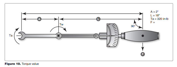
8384. (Refer to Figure 10.) The trunnion nut on an aircraft landing gear requires a torque of 320 inch-pounds. To reach the nut, a 2-inch straight adapter must be used on an 18-inch torque wrench. How many foot-pounds will be indicated on the torque wrench when the required torque of the nut is reached?
A—24.
B—28.8.
C—22.
(A) To solve this problem, use the formula:
TW = Ta × L / (L + A)
= 320 × 18 / (18 + 2)
= 288 inch-pounds
288 inch-pounds is divided by 12 to get 24 foot-pounds. (AM.II.E.K11) — FAA-H-8083-31
8385. A special bolt in a landing gear attachment requires a torque value of 440 inch-pounds. How many foot-pounds are required?
A—36.8.
B—38.
C—36.6.
(C) Inch-pounds can be converted into foot-pounds by dividing by 12. 440 inch-pounds is 36.6 foot-pounds. (AM. II.E.K11) — FAA-H-8083-31
8306. What would be the effect if the piston return spring broke in a brake master cylinder?
A—The brakes would become spongy.
B—The brake travel would become excessive.
C—The brakes would drag.
(C) If the piston return spring in a brake master cylinder were to break, the brakes would not release properly and they would drag. (AM.II.E.K12) — FAA-H-8083-31
8332. What is one effect a restricted compensator port of a master cylinder will have on a brake system?
A—The brakes will operate normally.
B—The reservoir will be filled by reverse flow.
C—The restriction will cause slow release of the brakes.
(C) It is possible for a restricted compensator port in a brake master cylinder to cause slow release of the brakes. With the port open when the brakes are released, there is an open passage between the master cylinder and the reservoir. But if the compensator port is clogged, some fluid can be trapped in the brake line, keeping the brake partially applied. (AM.II.E.K12) — FAA-H-8083-31
8334. Internal leakage in a brake master cylinder unit can cause
A—fading brakes.
B—slow release of brakes.
C—the pedal to slowly creep down while pedal pressure is applied.
(C) Internal leakage in the master cylinder of an aircraft brake system will cause the pedal to slowly creep down while pedal pressure is applied. (AM.II.E.K12) — FAA-H-8083-31
8345. What is the purpose of a compensating port or valve in a brake master cylinder of an independent brake system?
A—Permits the fluid to flow toward or away from the reservoir as temperature changes.
B—Assists in the master cylinder piston return.
C—Prevents fluid from flowing back to the reservoir.
(A) A compensating port in a brake master cylinder is a passageway open between the reservoir and the master cylinder when the brake is completely released. Fluid can flow from the reservoir into the master cylinder and from the master cylinder back into the reservoir as it expands or contracts because of temperature changes. (AM.II.E.K12) — FAA-H-8083-31
8349. Debooster cylinders are used in brake systems primarily to
A—reduce brake pressure and maintain static pressure.
B—relieve excessive fluid and ensure a positive release.
C—reduce the pressure to the brake and increase the volume of fluid flow.
(C) Debooster cylinders are used in brake systems to reduce the pressure applied to the brake and to increase the volume of fluid flowing into the brake. Brake deboosters are used only with brakes that have power brake control valves and get their fluid from the main aircraft hydraulic power system. (AM.II.E.K12) — FAA-H-8083-31
8352. If an airplane equipped with master cylinders and single-disc brakes has excessive brake pedal travel, but the brakes are hard and effective, the probable cause is
A—the master cylinder one-way cup is leaking.
B—worn brake linings.
C—worn brake disc causing excessive clearance between the notches on the perimeter of the disc and the splines or keys on the wheel.
(B) Badly worn brake linings can cause excessive brake pedal travel, but the brakes will be hard and effective once the pressure is built up. (AM.II.E.K12) — FAA-H-8083-31
8355. How is it determined in a master cylinder brake system that all of the air has been purged from the system?
A—By operating a hydraulic unit and watching the system pressure gauge for smooth, full scale deflection.
B—By depressing the brake and noting that the brake is firm and not spongy.
C—By measuring the amount of fluid return to the master cylinder upon brake release.
(B) If all the air has been purged from a master-cylinder brake system, the brake pedal will feel firm rather than spongy. (AM.II.E.K12) — FAA-H-8083-31
8357. If a brake debooster is used in a hydraulic brake system, its position in the system will be
A—between the pressure manifold of the main hydraulic system and the power brake control valve.
B—between the brake control valve and the brake actuating cylinder.
C—in the brake pressure line between the brake pedal and the brake accumulator.
(B) A brake debooster is located in the brake system between the power brake control valve and the brake actuator cylinder. The debooster lowers the pressure of the fluid supplied by the power-brake control valve to the actuator. (AM.II.E.K12) — FAA-H-8083-31
8359. Lockout deboosters are primarily pressure reducing valves that
A—allow full debooster piston travel without fluid from the high pressure side entering the low pressure chamber.
B—cannot allow full debooster piston travel without fluid from the high pressure side entering the low pressure chamber.
C—must be bled separately after brake bleeding has been completed.
(A) A lockout debooster is different from an ordinary debooster as it also serves as a hydraulic fuse. It will lock out the system after a given amount of fluid passes through it.
In an ordinary debooster, when fluid is lost, the piston moves to the bottom of its stroke and the riser unseats the ball check valve, and fluid from the power control valve passes through the piston shaft to replace the lost fluid.
In a lockout debooster, when fluid is lost, the piston moves to the bottom of its stroke and the riser unseats the ball check valve, but the spring-loaded lockout valve prevents fluid entering the lower chamber until the reset handle is lifted. (AM.II.E.K12) — FAA-H-8083-31
8374. When installing a chevron-type seal in an aircraft hydraulic cylinder, the open side of the seal should face
A—opposite the direction of fluid pressure.
B—up or forward when the unit is installed in a horizontal position.
C—the direction of fluid pressure.
(C) A chevron seal is installed in a hydraulic component in such a way that the open sides of the seal face in the direction of the fluid pressure. When the seal is properly installed, the hydraulic pressure will force the seal tightly against the cylinder walls. (AM.II.E.K12) — FAA-H-8083-31