Waves + optics edx
 Call Kai
 Learn
Learn Practice Test
 Spaced Repetition
 Match
Match Flashcards
 Knowt Play
1/32

Earn XP
Description and Tags
4 - 5.9
Name | Mastery | Learn | Test | Matching | Spaced | Call with Kai | Chat |
|---|
No analytics yet
Send a link to your students to track their progress
33 Terms
define wave, the two types, and differences
Transfer of energy (which can be as useful information) without the transfer of matter. because particles vibrate about fixed positions but do not travel with the wave
transverse - the oscillations are perpendicular to the direction of ET
longitudinal - oscillations are parallel to direction of ET
TW - not all waves need a medium to travel through where LWs do
LW - normally travel faster in a denser medium but TWs slower
Explain terms on a transverse wave graph : displacement and distance and time period
displacement - how far from the equilibrium point the wave has oscillated (y axis)
distance - how far the wave has travelled from its starting point (x axis)
time period, time taken for one complete oscillation (x axis) instead of distance
when distance is on the X axis one complete oscillation is the wavelength but then X axis is time then one complete oscillation is the time period
amplitude and wavelength peak and trough +
amplitude is the maximum displacement of a wave away from its undisturbed position (m) - can either be to peak or to trough
wavelength is the distance of one entire oscillation. Distance from one point on one wave to the same point on the next adjacent wave
peak - highest point of a wave
trough - lowest point of a wave
define frequency and time period + the wave equation for velocity and tp +
number of waves passing a point each second - no of complete oscillations per second (Hz)
The length in time it takes for one complete oscillation. The time it takes for a wave to pass a point (or f[Hz]^-1)
v = f * 𝞴
t = 1/f
wavefronts
line that connects all the same points of an identical wave in a set (can be peaks or troughs). When drawing ray diagrams with them the number of i fronts = r fronts, same length apart. when drawing them curved , the arc length increases. When drawing abt a WF, there is a virtual ray where the exact reflection happens
Examples of waves T L + how LWs travel
T - water waves, string waves, all electromagnetic radiation, seismic s waves
L - Tsunami waves, seismic P waves , sound waves
LWs travel by compressions and rarefactions . regions of high pressure due to particles being close together, regions of low pressure due to particles being farther apart
visible light spectrum in order of decreasing wavelength
wavelength ∝ frequency - with primary colours
RED orange yellow GREEN BLUE purple
RGB are primary colours because their wavelengths combine to make white light which is a mixture of all wavelengths - therefore every other colour comes from them
Black is absence of light
white is the combination of all wavelengths therefore they aren't on the spectrum
colour and object what they are dependent on
wavelengths of the light that are hitting it and colour of the object - this determines which wavelengths are absorbed transmitted and reflected therefore how it appears
an object reflects its own wavelengths and absorbs all other λ . Filters transmits their own λ while absorbing all other λ.
yellow - R + G
orange 2R + G (relative to yellow)
magenta = R + B
purple / indigo = R + 2B (relative to magenta)
cyan = G + B
specular refelction
reflection that occurs on a boundary that is smooth (to the atomic level) and flat and all the normals are in the exact same direction therefore all i rays will be reflected in the same direction creating a clear and precise image
diffuse reflection
reflection on an rough surface (to the atomic level) where the barrier is not flat resulting in the normals being at different directions resulting in the incoming rays being reflected all in different directions not resulting in a clear image.
what happens to the rays in reflection PTQ energy wise + law of reflection
𝜭i = 𝜭r
some of the light is abosorbed by the mirror (reflector) while the rest is reflected back, which therefore reduces the intensity of the ray,
and repeated multiple reflections will lead to more apsorption by the mirror therefore less light intensity of the emergent ray.
Ripple tank to measure speed of water ripples
shallow tray of water with a vibrating bar (connected to a power source) that creates surface waves of the water,
we have light @ top and paper underneath, when light shines produces an image of the waves on the paper
easiest way is to record the waves on a mobile phone as the footage can be slowed or to freeze time image completely.
place a ruler on the ripple tank
now we can see the wavefronts on the paper, and find the distance between 10 fronts - (actually 11 waves but the distances of the 10 spaces in between them)
divide by 10 to find avg. λ
freq and TP in a ripple tank
freq = no of waves passing a point each second , tp is the time it takes for a wave to pass a point (slo-mo phone)
so we firstly set the point on the paper (at a wave), and we count how many next waves pass in 10s - then divide 10 - Hz
TP - we see the time it takes for 10 waves to pass the point and divide by 10
use v=fλ for wavespeed
measurement errors, (less accuracy) of latency of human reaction time exist
redo @ diff. freqs to show that the speed is relatively constant due to the medium
to measure speed of sound -(phase - peaks aligned)
attach a signal gen to a speaker to gen sound of a specific freq. use 2 microphones and an oscilloscope to find the λ∿.
Set up the osc so the detected waves at each m.phone are separarate waves in phase . Start w both microphones next to the speaker then slowly move one away until the waves are still in phase but have moved exactly one λ apart.
measure this dist w a ruler and this is the λ of the wave.
then use v = f λ (f is the sound gen) to find speed in air
redo @ diff. freqs to show that the speed is relatively constant due to the medium - repeatable
speed of wave in solid
1) Measure and record the length of a metal rod,
2) Set up the apparatus of the rod hanging form a clamp with elastic bands, with a microphone near + hammer making sure to secure the rod at its centre.
3) Tap the rod with the hammer. Write down the peak frequency displayed by the computer.
4) Repeat this three times to get an average peak frequency to computer
5) Calculate the speed of the wave using v= f λ , where λ is equal to twice the length of the rod (due to standing wave resonance)
speed doesn’t change no matter what force hit, as frequency stays relatively constant. speed depends on the stiffness and density of the metal
how the human ear works until the ossicles
The sound wave travels down the auditory canal towards the eardrum. The pressure variations created by the sound wave exert a varying force on the eardrum causing it to vibrate. The vibration pattern of the sound waves creates the same pattern of vibration in the eardrum .The eardrum vibration is transferred to the ossicles
how the human ear works ossicles → brain
The vibration of these small bones amplifies the vibrations and then transfers the vibrations to the liquid in the cochlea located in the inner ear .Tiny hairs inside the cochlea detect the vibrations and create electrical impulses which travel along neurones in the auditory nerve to the brain giving the sensation of sound
why microphones and the human ear can only work for a limited range of frequencies + human range
The vibrating part of the device/ ear (such as the diaphragm or cone) has a natural frequency.
It vibrates most strongly near this frequency, so energy transfer between sound waves and vibrations is efficient.
At frequencies much higher or lower than the natural frequency, the diaphragm cannot vibrate effectively, so the vibrations are small and the conversion between sound and vibrations is inefficient so cannot be heard or picked up
Therefore the process only works over a limited frequency range.
human 20Hz - 20kHz. above ultra below infra sound
ultrasound use in foetal scanning
ultrasound travelling between 2 media, partial reflection occurs. They pass through the body, but when reaching the media boundary e.g. womb fluid and skin foetus, some of the waves are reflected back and detected. The exact timing and distribution of echoes are processed by a computer for a video image, and is completely safe.
US also used in echo-sonar to determine distance to the seabed or locate objects in deep water
seismic waves - PWs + SWs
infrasound waves for earthquakes and large scale events that travel through the earth
PWs are LWs and travel through liq and gas, faster than SWs
PWs only and are TWs travel through solids
seismic waves, carry E from the E.quake - waves detected w seismometers and are compared other seismologists around the world, the patterns of these waves give info abt the interior of the earth
How scientists find the internal structure of the Earth using SWs
SWs start at one point and spread out in the crust and mantle, but cannot go through the outer core therefore inner core, so there are large parts where they cannot be detected, called the SW shadow zone - tells us that earth must have a liq. core
How scientists find the internal structure of the Earth using PWs
PWs spread out through the crust, and the cores, but refract as they travel slower in liq. so there are PW shadow zones aswell, but more coverage than SW
(The whole mantle or core itself isnt the same p at all points, so the constant refraction makes the lines curved for both PWs and SWs )
refraction of lines in the core tells us that there must be a solid core inside the outer core
2 types of lenses
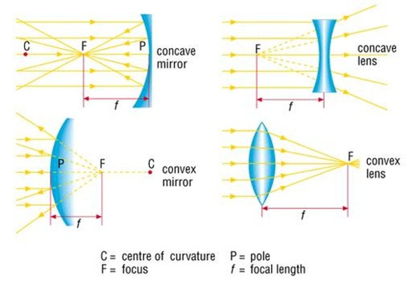
converging convex - bulge causes parallel rays of light to refract inwards and converge @ 1 single point (PF)
divergin concave - inward 'caveing' bulge causes parallel rays of light to be refracted outwards -
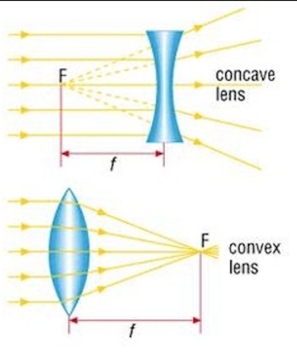
parts of light rays and lenses + power of lense
image is formed at the PF , where the rays appear to converge (come together) - dist between centre of wave and PF is the focal length f
middle ray is not refracted and this is the principal axis
to increase power : shorter f length / refracts light stronger
make the lens more curved or change material with a greater refractive index
real virtual difference
light rays actually do converge to form the image, which can be captured on the screen
light rays do not actually converge, come together where the image appears, appears as if they do only.
on a concave lens, the pf is virtual as light rays only appear to come from there
How to draw ray diagrams for virtual convex lenses
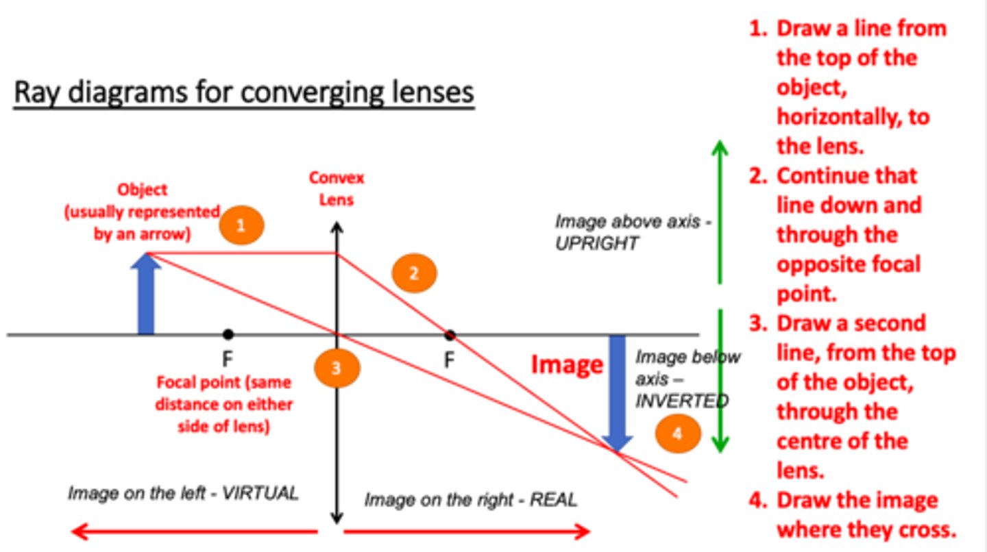
convex lens images depending on the focal lengths
u > 2f | dim , inv , real | |
u = 2f | same inv real | |
f < u < 2f u = f or u < f | inv , real , mgn up , mgn , vir |
how convex lenses work
lenses refract light , and bc the lens is curved anywhere on the lense is perpendicular to the surface - this means that lenses focus/disperse parallel rays of light into one or many more
refraction
change in velocity of a wave (WFs) and therefore direction from passing between 2 media with different refractive indices (densities)
𝛳i = 𝛳A = 𝛳C
𝛳 refrac = 𝛳B
When WF passes new medium at an angle, one side of the WF enters the new medium and changes speed before the other side, causing it to bend
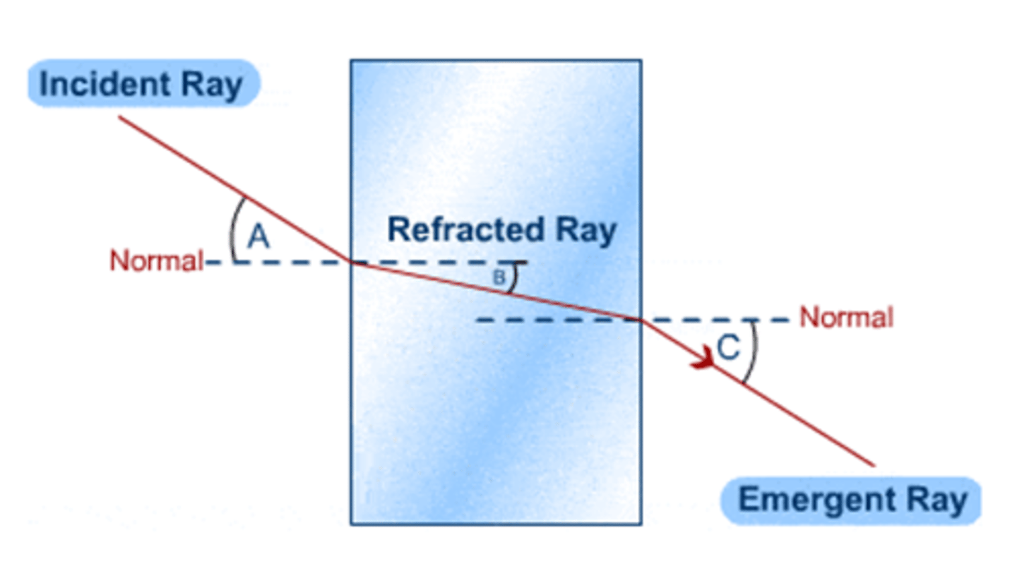
Direction change + straight perpendicular transmission
If the Waves enter the medium along the normal, the direction does not change
because 𝛳i = 0 then 𝛳r must also = 0
as the waves aren't at an angle, sides of the WF cannot bend due to changing speed first so no change in direction ∴ transmission
FAST - faster away , slower towards
TIR
2. When a light ray passes from a <ρ to ρ< medium, it can be reflected in the denser medium with no refracted ray
(need to go from a <ρ to ρ< medium bc then the ray bends away from the normal)
2. 𝛳i > 𝛳c (crit ang)
crit angle
use a semicircular glass block (curved so any point is at the normal) this means that there is only refraction as the light ray exits the glass rather than when it goes inside (transmission)
increase 𝛳i gradually until 𝛳r passes straight along the boundary , critical case where 𝛳i = 𝛳c - where 𝛳i > 𝛳c TIR
uses of TIR
endoscopy with no major surgery needed
light travels through the tube by TIR into the patient and back though another fibre - timing and distribution of waves are analysed by a computer
other optical devices like binocular prisms