CS 2110: Binary, Data Types, and Logic Circuits Review
 Call Kai
 Learn
Learn Practice Test
 Spaced Repetition
 Match
Match Flashcards
 Knowt Play
1/59

There's no tags or description
Looks like no tags are added yet.
Name | Mastery | Learn | Test | Matching | Spaced | Call with Kai | Chat |
|---|
No analytics yet
Send a link to your students to track their progress
60 Terms
Decimal
our 'normal' number counting system (base 10)
Binary
base 2
Octal
base 8
Hexadecimal
base 16
Unsigned Binary
Non-negative binary numbers
Signed Magnitude
We use the leftmost bit (MSB) to indicate the sign.
2's Complement
Most common type of representing positive and negative numbers in binary
2's complement addition
Adding two 2's complement numbers is the same process as adding two unsigned binary numbers.
Overflow
What if I don't have enough bits to store the output of my addition?
Sign Extension
The same number can be expressed with different word-lengths.
Binary to Decimal Conversion
Write down the binary number, list the powers of 2 underneath the numbers from right to left, and add all powers of 2 that are underneath a '1' binary number.

Detecting Overflow
For 2's complement addition, there are two ways of detecting overflow: 1. Adding two numbers with the same sign resulting in a number of the opposite sign. 2. If the carry in and carry out of the last bit are different.
Additive Inverse in 2's Complement
To find the additive inverse of a number using 2's complement, you flip the bits and add 1.
Binary Subtraction
Binary subtraction can now be done by performing binary addition but with the 2's complement of the number to subtract.
Leading Zeroes in Sign Extension
To sign-extend an unsigned binary number, you need to add leading zeroes to the beginning of the number.
Appending Sign Bit in Sign Extension
To sign extend a 2's complement binary number, you need to append the sign bit to the most significant bit (left) end.
Carry Out in Unsigned Addition
For unsigned binary addition, there is overflow if there is a carry out bit.
Carry In and Carry Out
If the carry in and carry out of the last bit are different, overflow occurs.
Two Representations for Zero
There are two representations for zero: '0000' (+0) and '1000' (-0).
Typical Arithmetic Issues
Typical arithmetic issues occur when operations yield incorrect results, such as 0110 (6) + 1001 (-1) = 1111 (-7), not -5.
Example of Unsigned Binary
Range of 4-bit binary -> [0, 24 - 1] = [0, 15]
Signed Magnitude Binary Range
[-2n-1 + 1, 2n-1 - 1]
2's Complement Binary Range
[-2n-1, 2n-1 - 1]
IEEE 754 Formula
(-1)^S * 1.M * 2^(E-127)
Normal numbers exponent range
Exponent range from -126 to +127, -127 and +128 are reserved for special cases.
NOT A
Syntax: Ā, ¬A, A', ~A, !A; 1 = true, 0 = false.
AND Operation
Syntax: AB, A&B, A•B, A∧B; A AND 0 = 0, A AND 1 = A.
OR Operation
Syntax: A+B, A∨B; A OR 0 = A, A OR 1 = 1.
XOR Operation
Syntax: A⊕B, A^B; A XOR 0 = A, A XOR 1 = 1.
Bitwise Boolean Operations
Performed between two binary numbers, resulting in logical operations between each respective bit.
Bit Vector
a series of bits that represent some number
Bit Mask
a bit vector that is applied to another bit vector (input) with a bitwise operation to transform the input
Bit Masking
AND can be used to clear a bit (A AND 0 = 0)
Bit Masking Example
EX: 1011012 AND 1111102 = 1011002
Bit Masking OR
OR can be used to set a bit (A OR 1 = 1)
Bit Masking OR Example
EX: 1011002 OR 0000012 = 1011012
Bit Masking XOR
XOR can be used to toggle a bit
Bit Masking XOR Example
EX: 0110002 XOR 0000012 = 0110012
NOT Operation
~A
De Morgan's Law
To simplify expressions using De Morgan's Law: Distribute the NOTs and identify any common rules/properties that can help simplify further
De Morgan's Law NOTing
NOTing an operator flips it: NOT(AND) = OR, NOT(OR) = AND
N-Type Transistors
Must be connected to ground; If supplied with an amount of volts > 0, we have a closed circuit, representing a logical 1.
P-Type Transistors
Must be connected to power; If supplied with an amount of volts > 0, we have an open circuit, representing a logical 0.
NOT Gate
Also called an inverter; Outputs the opposite of the input
NOR Gate
NOT (OR) Gate; For a NOR gate with n inputs, we use n P-type transistors and n N-type transistors.

Common Properties/Rules
A + (B + C) = (A + B) + C, A * (B + C) = (A * B) + (A * C), A + (A * B) = A
Common Identities
A + 0 = A, A * 0 = 0, A * 1 = A, A * ~A = 0, A + ~A = 1
N-Type vs P-Type Comparison
They have the opposite effect; notice the bubble!
OR Gate
ORs two inputs
OR Gate Transistors
For an OR gate with n inputs, we use: n + 1 P-type transistors, n + 1 N-type transistors
NAND Gate
NOT (AND) Gate
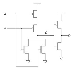
NAND Gate Transistors
For a NAND gate with n inputs, we use: n P-type transistors, n N-type transistors
AND Gate
ANDs two inputs
AND Gate Transistors
For an AND gate with n inputs, we use: n + 1 P-type transistors, n + 1 N-type transistors
Decoder
Selects exactly one output based on which of the input bits are set
Decoder Outputs
If there are n selector bits, then there are 2n possible outputs
Multiplexer (MUX)
Selects between multiple inputs using a selector
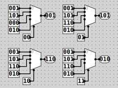
MUX Inputs
If there are 2n inputs, then there are n selector bits
1-bit adder
When adding two inputs, say A and B (1-bit binary numbers), we must consider the bits of those numbers, as well as any carry in bits.
1-bit adder Output
The output is both the sum and any carry out from the addition