Week 2 Biophysics & Carto 3 System
 Call Kai
 Learn
Learn Practice Test
 Spaced Repetition
 Match
Match Flashcards
 Knowt Play
1/37

There's no tags or description
Looks like no tags are added yet.
Name | Mastery | Learn | Test | Matching | Spaced | Call with Kai | Chat |
|---|
No analytics yet
Send a link to your students to track their progress
38 Terms
Components of RF circuit
RF Gen → RF cable & cath → patient → grounding pad/indifferent electrode
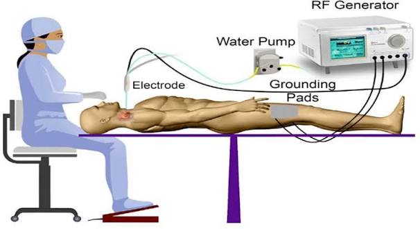
Importance of grounding pad
Prevents dangerous heat buildup in patient body
Collects energy and funnels back to generator
Distributes electrical energy across large surface area
Improper placement can increase impedance (small area concentration) & disrupt flow of energy (potentially cause burns)
Patient size and location very important
larger patient = higher impedance
farther from heart = higher impedance (want shorter distance)
Resistive Heating
Heat directly adjacent to electrode
hottest portion
resistance in myocardium causes ions to become agitated and cause heat in the tissue
3 mm
Conductive Heating
Expanded area from resistive heating area
Majority of lesion size
Allows damage to penetrate deeper into heart
7 mm
need proper ablation contact & time
3 factors affecting lesion size
Time (s): duration correlates to lesion size
Contact F (g): Pressure caused by catheter tip
Can be monitored by US to assess contact
TPI = tissue proximity index (sparkle = good)
varipulse = bubbles show = good
Power (W): GREATEST role
Amount of RF energy delivered to the tissue
power delivered does not equal energy received
Impedance
Resistance to electrical flow between catheter tip and grounding pad
Should see gradual drop during ablation (less impedance = dead tissue)
Important temperatures RF ablation
50-55 C = Cell death
75 C = Char & Coagulation
Overheating & decrease efficiency of energy delivery
Causes sharp rise in impedance
100 C = steam pop
overheating & over ablation
Apoptosis with PFA
Irreversible cell death from applied electrical fields that cause pores in the cell membrane causing an imbalance and eventually death
tissue specific & maintains tissue elasticity
Distance from other structures decreases risk of harm to other structures
stunning can occur (improper time for lesion formation)
Variable in PFA waveform
Pulse strength & duration
Bipolar vs unipolar
Monophasic vs biphasic
# of pulses
frequency
Importance of good contact PFA
Need multiple applications ( 4 per PV for varipulse)
Good contact needed for increased lesion depth
Uniform cell death in blast zone
Power modes for the NGen
Power controlled mode: RF energy @ a fixed target power
Temp controlled mode: Temp & power change
QDOT
Changes power & fluid output to prevent overheating
Connections to the NGen
NGen Pump
Console & power supply
Monitor
Workstation
Carto3 System Tower
PIU core of Carto
Receives real time location & ECG calculations
Interface with cath & other equipment
Info goes into PIU and spits out back to WS
Workstation
Gathers data from PIU
Creates 3D electroanatomical map of heart
DVI cables
Connects secondary monitor to carto WS
Allows primary monitor image to display on secondary monitor in real time
Ethernet
Connects NGen generator to Carto WS
Connects NGen monitors & console
Navigant = WS
US = US
IC Out (back of PIU)
Transmits intracardiac signals from PIU to recording system
Fiber optics
Connects WS to PIU (transfers data)
Serial communication cable
Connects console to recording system
Patch unit
Connects patches & transfers data from patient to PIU
Patches
Measure high f & low power current emitted from cath electrode connected to the system
Determines initial body coordinate system (BCS) based on 3 back patches & relative to each other & magnet
Location pad/magnet
Contains magnetic coils to generate magnetic field to see cath location
ECG In
Transfers ECG data from patient to PIU
ECG Out
Transfers body surface ECG signals from PIU to recording system
NGen console to PIU cable
Connects PIU to NGen console (data transfer)
Pump
Sets irrigation flow rate for navigational caths
Console & power supply
RF generator solution for current & future cathetera
Automatically recognizes NAV caths & loads default ablation & irrigation settings
Monitor
Controls pump & remote monitor
Controls system
Electroanatomical Mapping
Recording and cataloging endocardial electrical data & creating detailed rendering of heart anatomy
Impedance based tech
Catheter is placed and then impedance can be measured & cath can be visualized
Impedance measured between 2 patches
Pros:
Any cath can be visualized
Cons:
Non-linear field
Biological processes can disturb impedance
Impedance can change w/ each cath inserted
Magnetic Technology
Uses magnent, patches, and sensor based cath
Sensor measures strength of magnetic field based on distance from each coil on location pad
tip location = x,y,z axis
orientation = roll, pitch, yaw
Pros: VERY accurate
Cons: Only supports NAV based caths (need to have sensors)
Current based tech
System generates small current & sends to caths → each electrode emits unique f which is collected by patches
Pros:
Does not need to be magnetic to be visualized
Carto Advanced Cath Location (ACL)
Combo of magnetic & current based technology
Location & current ratio stored everywhere where the cath visits → system links ratio w/ magnetic location → visual location of cath
Sensor based cath can create matrix (made of current ratios taken from electrodes) & match to magnetic location → can see non-NAV/non-sensor based cath
Pros:
Visualization of any cath with electrodes
Creates linear field
Not impacted by biology changes
Very accurate (1 mm)
6 degrees of freedom (DOF) = more precise
MAP Port
NAV therapeutics ONLY
Cables with red end
Ex: QDOT, STSF, navistar
Ref/DECA
Any advanced diagnostic & diagnostic caths
Auto or non-auto ID
Max of 10 poles
Pin box
Ex: Decanav, cs cath, auto ID Webster (& non-auto)
Quad A&B
Only webster
Diagnostic caths
Max 4 poles
Ex: Vizigo sheath, auto ID web HIS
20A & 20B Port
Connects advanced diagnostic & diagnostic
Max of 20 pole
20A supports TPI
Ex: Pentaray, Octaray, LAsso, Pin box, Decanav
Deca port
Only webster
Diagnostic
10 poles
Ex: Auto/non cs, auto/non his, auto/non quad