Digital Electronics Ch. 4 "Signal Processing and Conditioning with Two-Terminal Nonlinear Devices"
1/8
Earn XP
Description and Tags
Diodes, Transfer characteristics, and Rectifiers
Name | Mastery | Learn | Test | Matching | Spaced | Call with Kai |
|---|
No analytics yet
Send a link to your students to track their progress
9 Terms
Transfer Characteristics of a Circuit
Describes the relationship between the input signal and the output signal. (Vin vs. Vout)
Clipping and Limiting Circuits
A term used interchangeably to mean a circuit that limits (or "clips") part of an input signal above or below a certain voltage threshold using diodes and sometimes reference voltages. It alters the waveform shape by removing portions that exceed specific voltage levels.
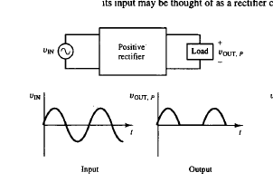
Rectifier
One or more diodes appear in series between the input and output ports, and the output is applied to a passive load element. The primary function is to change an AC input voltage into a DC voltage.
Half-Wave Rectifier
Using one diode, outputs positive values 0 < Vin < (Vmax - Vf) or negative values 0 > Vin > (Vmin + Vf). Output is pulsating DC, not smooth.
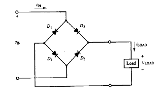
Bridge Rectifier
Using four diodes, this rectifier allows for current to flow in for both positive and negative values of Vin but always in the positive iload direction.
Half-Wave Rectifier Power Supply
Includes a diode and a capacitor. A complete circuit used to deliver DC power. Much smoother DC than original but still has a ripple.
Bridge Rectifier Power Supply
Includes four diodes and a capacitor, has usable DC power, and often includes voltage regulation.
Ripple Voltage / Factor
The bumpiness of the output waveform. Ideally, the ripple should be small. A high ripple means poor voltage regulation. It should be minimized for quality DC supplies.
Precision Rectifier
A diode-drop problem can be overcome by adding one or more diodes to an op-amp. An Op-Amp can effectively bypass the 0.7 V needed to turn on the diode. Can be half-wave or full wave.