MOD 4 - Digital Detectors
1/29
There's no tags or description
Looks like no tags are added yet.
Name | Mastery | Learn | Test | Matching | Spaced | Call with Kai |
|---|
No study sessions yet.
30 Terms
Classification of Digital Imaging
CR
DR (Direct Radiography)
Flat Panel (Mammography)
IDR (Indirect)
Flat Panel (C-arm)
Non-Flat Panel (Siemen’s Detectors, II of Fluoro)
Scanned Projection Radiography (CT)
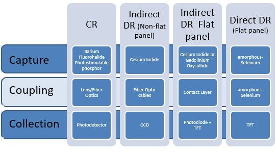
Elements of a Digital Detector
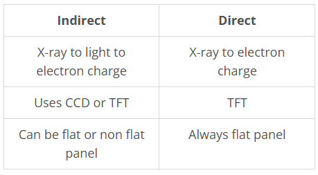
Capture: x-ray → light/electrical signal
Coupling: transmit the signal into the collection element
Collection: collects and converts the signal into electronic/analog signal
ADC
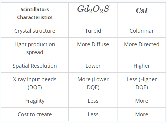
Which capture element structure increases spatial resolution
A columnar structure (CsI) allows for less light spread, therefore it provides better spatial resolution
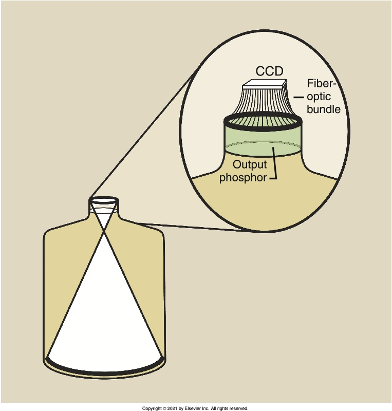
CCC Elements of Indirect Non-flat Panel
Capture:CsI
Coupling: fiber optic cables
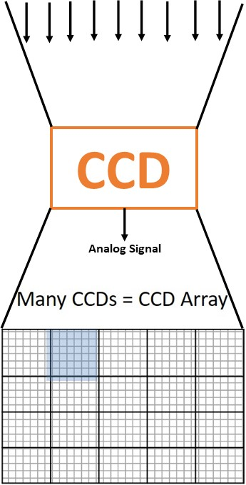
Collection: Charge Coupled Devices (CCD)
CCD advantage
highly sensitive to low light, responds to very dim and very bright lights therefore has a wide dynamic range
CCC Elements of Indirect Flat Panel
Capture: CsI or GaO
Coupling: contact layers
Collection: photoiodide a-Si + TFT or CCD
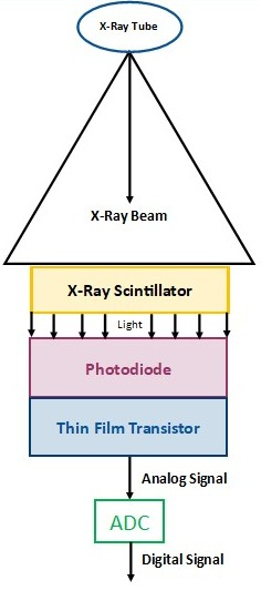
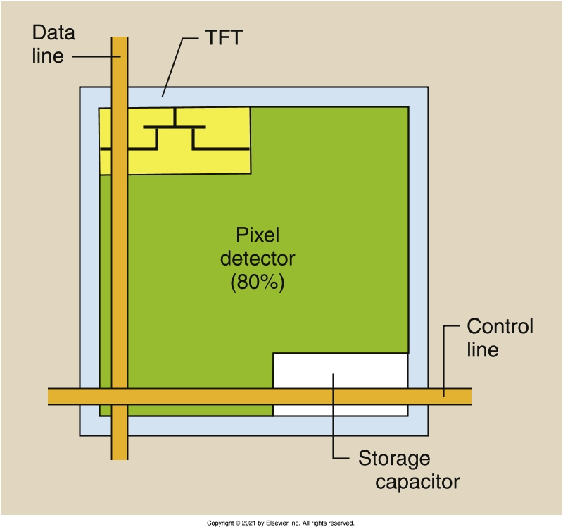
TFT’s function
controls when each DEL sends it's information, and this info is stored in the top-thin layer of the TFT called the storage capacitator
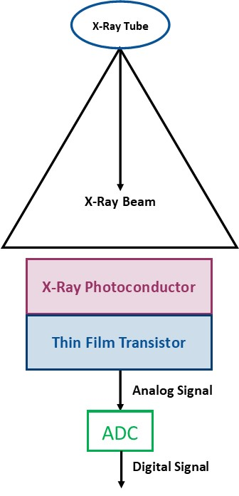
CCC Elements of Direct Flat Panel Detectors
Capture and Couple: a-Se which is the photoconductor layer
Collection: TFT
Pixel Fill Factor
where the capture element makes up 80% of the pixel space, and the rest 20% are the capacitators and TFT where it isn’t able to respond to scintillator created light
MEANING, the SR increases with decreased pixel size ONLY if the TFT and Capacitator size are created smaller
Pixel Pitch
the distance between each central point of two adjacent pixels in a detector array
Indirect vs. Direct Digital Systems
Indirect Scintillation Layer Differences
Principal of Digital Fluoro (DF)
increased acquisition speed and the ability to post-process digital images
Interrogation Rate
time required for the generator to activate the tube to the desired exposure = acquisition rate
Extinction Time
time required to terminate the exposure
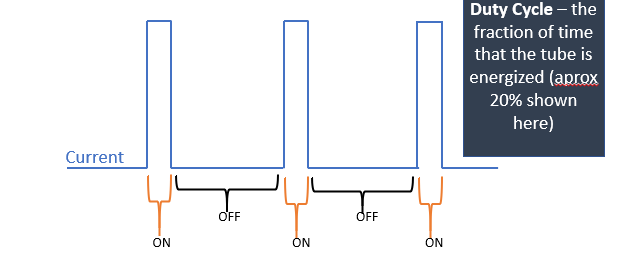
Duty Cycle
The fraction of time that the tube is activated
Types of DF Receptors
CCD
Flat Panel DR receptors
CCD DF
coupled to the output phosphor either directly or with fiberoptics, the CCD linear response improves IQ compared to conventional fluoro
Advantages of FPD over II Fluoroscopy
improved image accuracy
consistent image quality across the whole image
more compact and lighter
High DQE → fast duty cycles
3D multiplanar
Magnification Mode in FPD Fluoroscopy
reduces the amount photon interactions for each detector element → increased image noise → increased mA
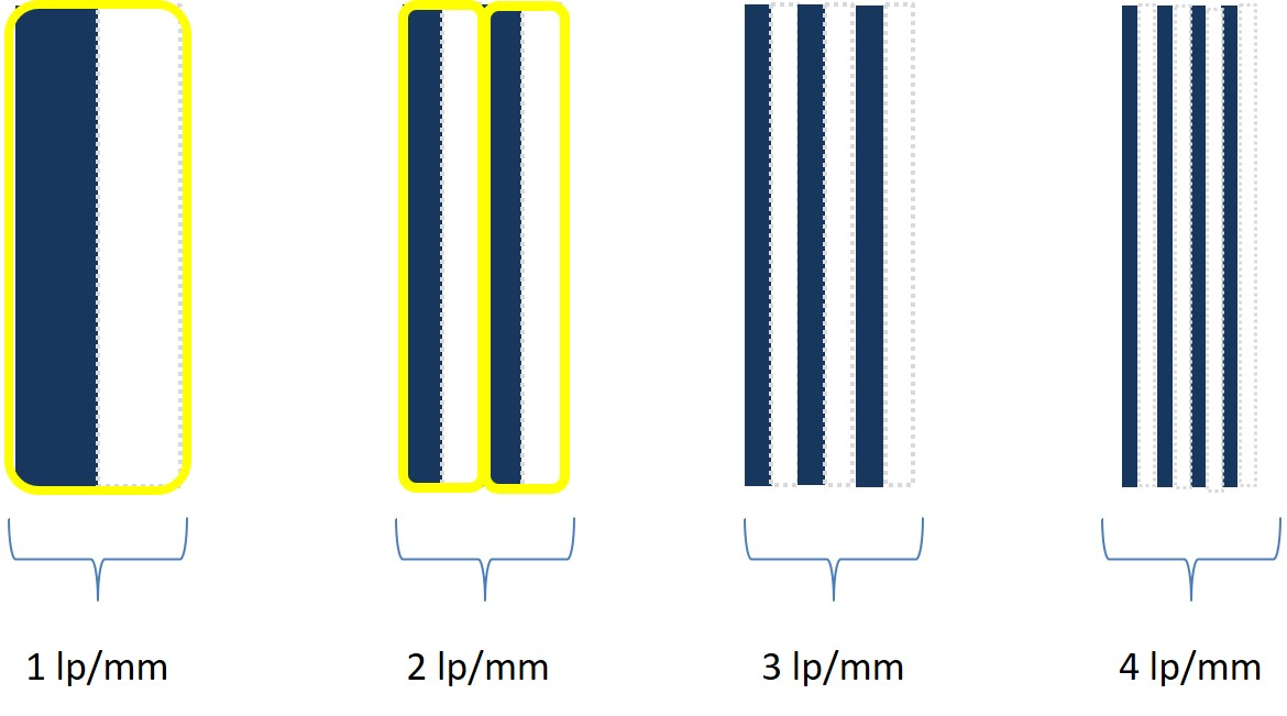
contrast and spatial resolution relationship
while CR is independent of SR, SR increases with increased CR
higher spatial frequency =
more line pairs within one mm
Modulation Transfer Function
detector's ability to accurately detect and display objects true to life
impossible to have MTF = 1; all MTF < 1
the MTF as the objects imaged get smaller
MTF rate decreases when object becomes smaller then the pixel/detector element size
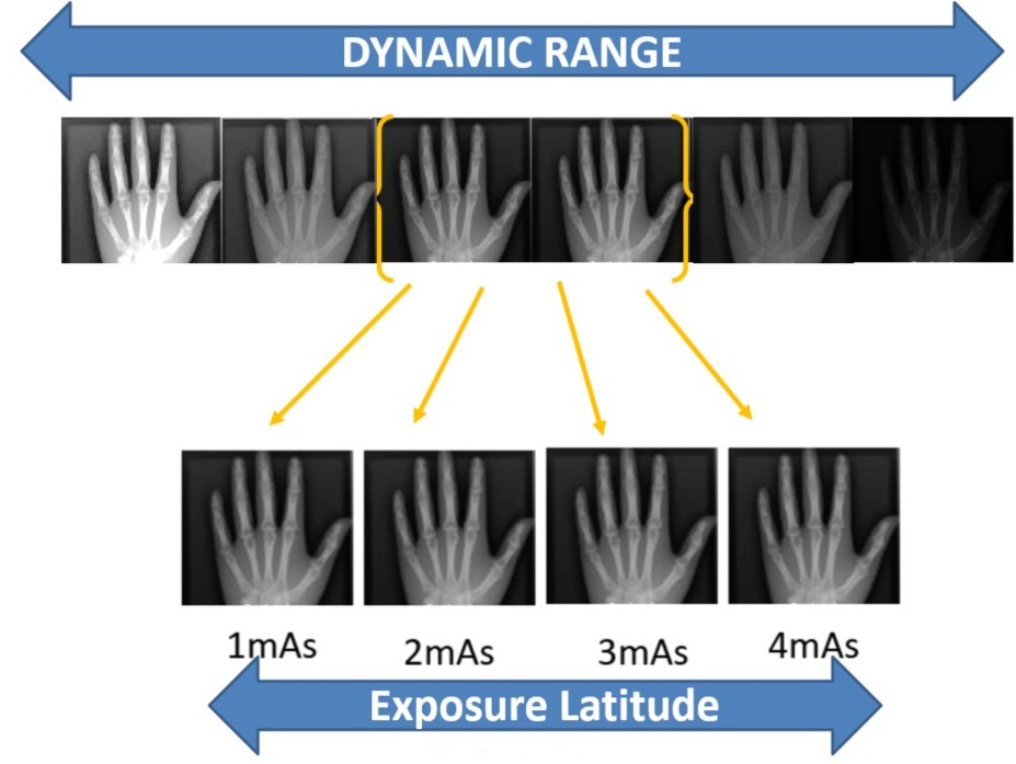
Exposure Latitude
the ability to produce images at different exposure values all with good/same quality
higher dynamic range = wider exposure latitude
Detective Quantum Efficiency (DQE)
the detector absorption efficiency for a wide range of photon energies
high DQE = less dose required
increased kV = ?DQE
decreased DQE
which detector material has the highest DQE
a-Se used in Direct DR
Digital Image Lag
previous image residues shown when the capacitator fails to reset to zero