Systems 3/4 - Electronics 3 - Diagrams

studied byStudied by 55 people
5.0(1)
Get a hint
Hint
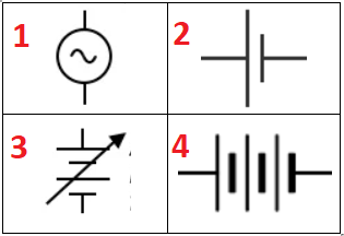
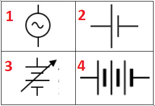
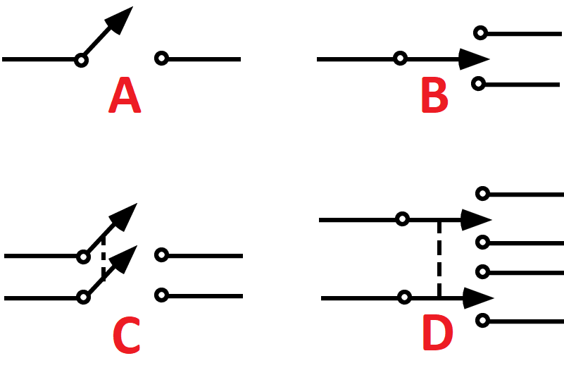
<p>What do these diagrammatic symbols refer to?</p><p></p>

What do these diagrammatic symbols refer to?

1 / 29

encourage image

There's no tags or description

Looks like no one added any tags here yet for you.

30 Terms

1
<p>What do these diagrammatic symbols refer to?</p><p></p>

What do these diagrammatic symbols refer to?

  1. AC power supply

  2. Cell

  3. Variable Battery

  4. Battery

<ol><li><p>AC power supply</p></li><li><p>Cell</p></li><li><p>Variable Battery</p></li><li><p>Battery</p></li></ol><p></p>
New cards
2
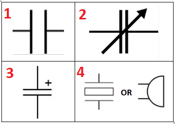
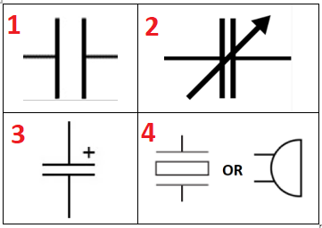
<p>What do these diagrammatic symbols refer to?</p>

What do these diagrammatic symbols refer to?

  1. Capacitor

  2. Variable capacitor

  3. Polarised capacitor

  4. Piezo-electric buzzer

<ol><li><p>Capacitor</p></li><li><p>Variable capacitor</p></li><li><p>Polarised capacitor</p></li><li><p>Piezo-electric buzzer</p></li></ol><p></p>
New cards
3
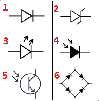
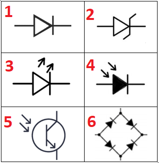
<p>What do these diagrammatic symbols refer to?</p>

What do these diagrammatic symbols refer to?

  1. Diode

  2. Zener Diode

  3. Light Emitting Diode (LED)

  4. Photo Diode

  5. Photo Transistor

  6. Rectifier (AC > DC)

<ol><li><p>Diode</p></li><li><p>Zener Diode</p></li><li><p>Light Emitting Diode (LED)</p></li><li><p>Photo Diode</p></li><li><p>Photo Transistor</p></li><li><p>Rectifier (AC &gt; DC)</p></li></ol><p></p>
New cards
4
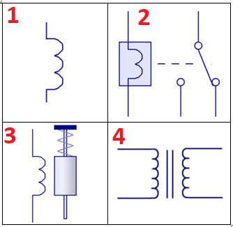
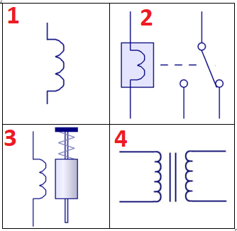
<p>What do these diagrammatic symbols refer to?</p>

What do these diagrammatic symbols refer to?

  1. Inductor

  2. Relay

  3. Solenoid

  4. Transformer

<ol><li><p>Inductor</p></li><li><p>Relay</p></li><li><p>Solenoid</p></li><li><p>Transformer</p></li></ol><p></p>
New cards
5
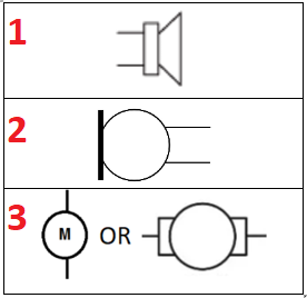
<p>What do these diagrammatic symbols refer to?</p>

What do these diagrammatic symbols refer to?

  1. Speaker

  2. Microphone

  3. DC motor

New cards
6
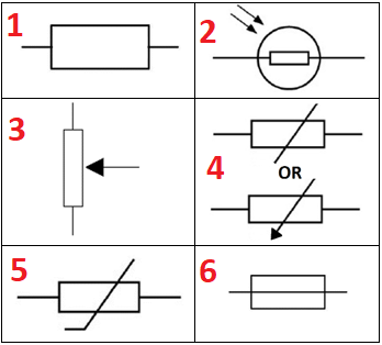
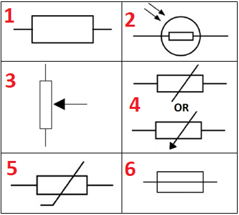
<p>What do these diagrammatic symbols refer to?</p>

What do these diagrammatic symbols refer to?

  1. Resistor

  2. Light Dependent Resistor (LDR)

  3. Potentiometer

  4. Varying Resistor

  5. Thermistor

  6. Fuse

<ol><li><p>Resistor</p></li><li><p>Light Dependent Resistor (LDR)</p></li><li><p>Potentiometer</p></li><li><p>Varying Resistor</p></li><li><p>Thermistor</p></li><li><p>Fuse</p></li></ol><p></p>
New cards
7
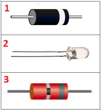
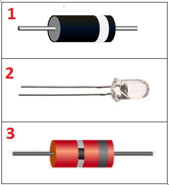
<p>What do these images refer to?<br>(They look like this in real life)</p>

What do these images refer to?
(They look like this in real life)

  1. Diode

  2. Light Emitting Diode (LED)

  3. Zener Diode

<ol><li><p>Diode</p></li><li><p>Light Emitting Diode (LED)</p></li><li><p>Zener Diode</p></li></ol><p></p>
New cards
8
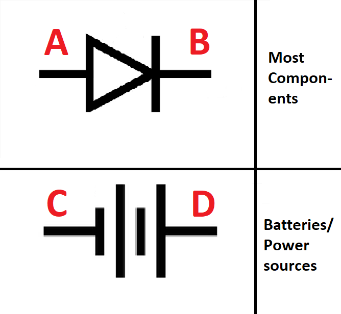
<p><span style="color: #ff0000"><strong>(rare)</strong></span></p><ol><li><p>Which Letters are Anodes/ Cathodes?</p></li><li><p>Which way does conventional current flow for each?</p></li></ol><p></p>

(rare)

  1. Which Letters are Anodes/ Cathodes?

  2. Which way does conventional current flow for each?

  1. Anode: A, C (Anode = ANd = +), Cathode B, D

  2. A > B, C > D (Current flows from anode to cathode in all components (draw) other than cells (supply))

<ol><li><p>Anode: A, C (Anode = ANd = +), Cathode B, D</p></li><li><p>A &gt; B, C &gt; D (Current flows from anode to cathode in all components (draw) other than cells (supply))</p></li></ol><p></p>
New cards
9
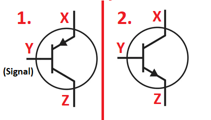
<ol><li><p>What is the name for each component?</p></li><li><p><span style="color: #ff0000"><strong>(rare)</strong></span> What is X, Y, Z labeled for each?</p></li><li><p><span style="color: #ff0000"><strong>(tough)</strong></span> Which way does the signal current need to flow to switch on the components?</p></li></ol><p></p>
  1. What is the name for each component?

  2. (rare) What is X, Y, Z labeled for each?

  3. (tough) Which way does the signal current need to flow to switch on the components?

Bipolar Junction Transistor (BJT), 1 = PNP, 2 = NPN

NPN: X = Emitter, Y = Base, Z = Collector, Flow = Emitter > Base

PNP: X = Collector, Y = Base, Z = Emitter, Flow = Base > Emitter
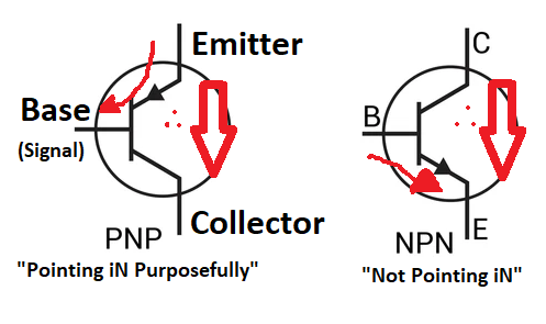
<p>Bipolar Junction Transistor (BJT), 1 = PNP, 2 = NPN</p><p>NPN: X = Emitter, Y = Base, Z = Collector, Flow = Emitter &gt; Base</p><p>PNP: X = Collector, Y = Base, Z = Emitter, Flow = Base &gt; Emitter</p><p></p>
New cards
10
<p>What do these diagrammatic symbols refer to?</p>

What do these diagrammatic symbols refer to?
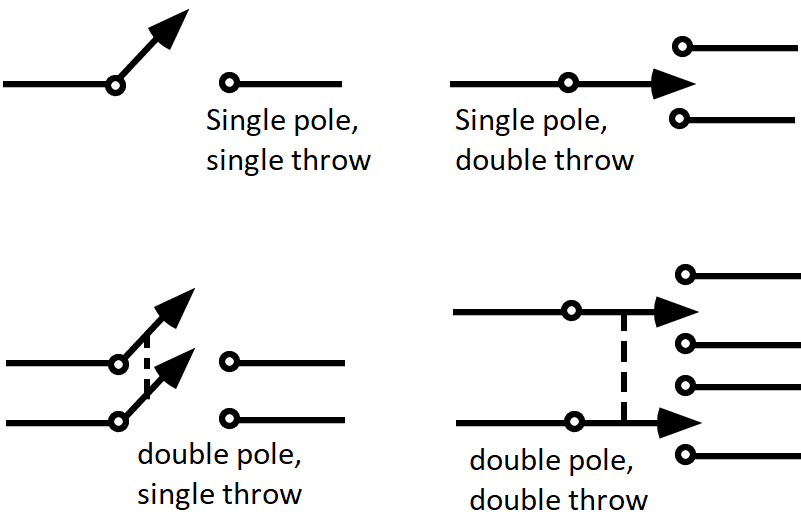
knowt flashcard image
New cards
11
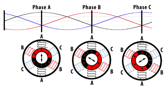
<ol><li><p>Can you identify what this graph refers to?</p></li><li><p>What component uses it directly?</p></li><li><p><span style="color: #ff0000"><strong>(rare)</strong></span> In Australia, what is the peak value for each coloured line and in what units?</p></li><li><p><span style="color: #f30000"><strong>(rare) </strong></span>What’s the expected frequency?</p></li></ol><p></p>
  1. Can you identify what this graph refers to?

  2. What component uses it directly?

  3. (rare) In Australia, what is the peak value for each coloured line and in what units?

  4. (rare) What’s the expected frequency?

  1. Three phase power

  2. AC induction motor

  3. 230V in AUS

  4. 50hz in AUS

<ol><li><p>Three phase power</p></li><li><p>AC induction motor</p></li><li><p>230V in AUS</p></li><li><p>50hz in AUS</p></li></ol><p></p>
New cards
12
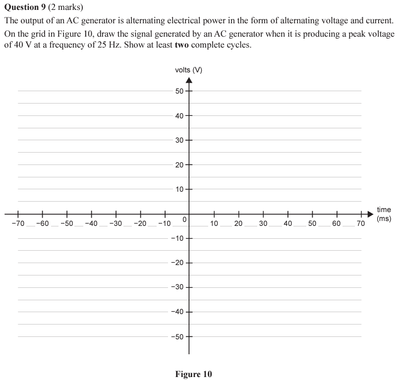
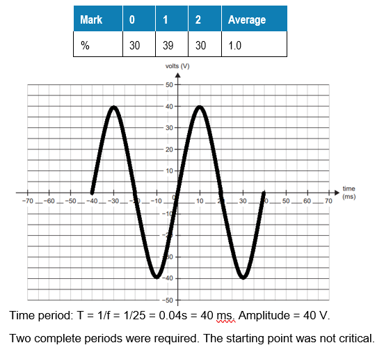
<ol><li><p>Work out which formula you need to calculate the period</p></li><li><p>On a sine wave, what does the period look like?</p></li><li><p>If a transformer reduces the voltage in half, what does the graph look like?</p></li></ol><p></p>
  1. Work out which formula you need to calculate the period

  2. On a sine wave, what does the period look like?

  3. If a transformer reduces the voltage in half, what does the graph look like?

  1. f = 1/T is on the sheet (T is time), so T = 1/f

  2. Peak to peak is one period, question asks for 2 whole waves.

  3. Half the whole height

<ol><li><p>f = 1/T is on the sheet (T is time), so T = 1/f</p></li><li><p>Peak to peak is one period, question asks for 2 whole waves.</p></li><li><p>Half the whole height</p></li></ol><p></p>
New cards
13
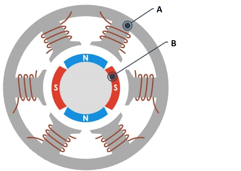
<ol><li><p>Is this a brushless or brushed DC motor?</p></li><li><p>What is A and B named?</p></li></ol><p></p>
  1. Is this a brushless or brushed DC motor?

  2. What is A and B named?

  1. Brushless

  2. A = stator coils, B = rotor (permanent magnet)
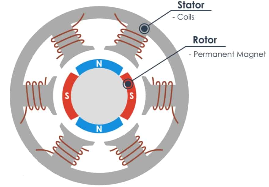
<ol><li><p>Brushless</p></li><li><p>A = stator coils, B = rotor (permanent magnet)</p></li></ol><p></p>
New cards
14
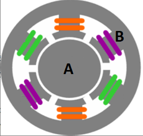
<p>This is an AC induction motor diagram</p><ol><li><p>What is A and B named?</p></li><li><p>What makes the green, orange and purple wires different?</p></li></ol><p></p>

This is an AC induction motor diagram

  1. What is A and B named?

  2. What makes the green, orange and purple wires different?

  1. A = Squirrel cage rotor, B = Stator coils

  2. They are separate AC currents out of phase by 120 degrees
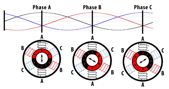
<ol><li><p>A = Squirrel cage rotor, B = Stator coils</p></li><li><p>They are separate AC currents out of phase by 120 degrees</p></li></ol><p></p>
New cards
15
<p><span style="color: #ff0000"><strong>(rare)</strong></span><br>RMS voltage</p><ol><li><p>When would you use this calculation?</p></li><li><p>If you needed to calculate the RMS voltage, what would the equation look like?</p></li></ol><p></p>

(rare)
RMS voltage

  1. When would you use this calculation?

  2. If you needed to calculate the RMS voltage, what would the equation look like?

  1. To convert between AC power peaks and the equivalent constant DC voltage (rectification) (assuming no losses)

  2. Vrms = Vpeak/√2

New cards
16
<ol><li><p>What is the general term for this circuit?</p></li><li><p>What does the capacitor do?</p></li><li><p><span style="color: #ff0000"><strong>(rare) </strong></span>Which capacitor is a good choice to use?</p></li><li><p>What other component could be added to the DC side?</p></li></ol><p></p>
  1. What is the general term for this circuit?

  2. What does the capacitor do?

  3. (rare) Which capacitor is a good choice to use?

  4. What other component could be added to the DC side?

  1. Rectifier

  2. Smoothing current

  3. Electrolytic bc. they’re large capacity

  4. A Zener diode in reverse bias for clamping

New cards
17
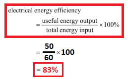
<ol><li><p>What is the voltage at Vs1 and Vs2 assuming no losses?</p></li><li><p>If the measured voltage on the load is 50V, what is the efficiency?</p></li></ol><p></p>
  1. What is the voltage at Vs1 and Vs2 assuming no losses?

  2. If the measured voltage on the load is 50V, what is the efficiency?

  1. 60V

  2. 83% approx.

<ol><li><p>60V</p></li><li><p>83% approx.</p></li></ol><p></p>
New cards
18
<ol><li><p><span style="color: #ff0000"><strong>(rare)</strong></span> Is there a con to using this simpler rectifier (instead of the full-bridge)?</p></li><li><p>Where would the efficiency losses be?</p></li><li><p>How would the loss appear to a person using the device?</p></li></ol><p></p>
  1. (rare) Is there a con to using this simpler rectifier (instead of the full-bridge)?

  2. Where would the efficiency losses be?

  3. How would the loss appear to a person using the device?

  1. Only half of the output coils are used at a time (because of the diode arrangement). Also, half as many diodes = needing higher power diodes

  2. The coils, the capacitor, a potential Zener Diode

  3. Heat

New cards
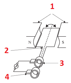
19
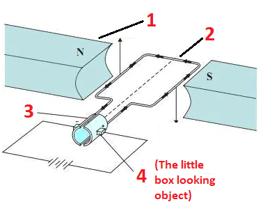
<ol><li><p>What is this whole component called specifically?</p></li><li><p>Name the 4 labeled parts</p></li></ol><p></p>
  1. What is this whole component called specifically?

  2. Name the 4 labeled parts

Brushed DC motor

  1. Stator magnets

  2. Rotor coil (rare - armature)

  3. Split ring (rare - commutator)

  4. Brushes

<p>Brushed DC motor</p><ol><li><p>Stator magnets</p></li><li><p>Rotor coil <span style="color: #ff0000"><strong>(rare - armature)</strong></span></p></li><li><p>Split ring <span style="color: #ff0000"><strong>(rare - commutator)</strong></span></p></li><li><p>Brushes</p></li></ol><p></p>
New cards
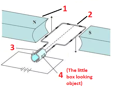
20
<ol><li><p>What is this component called specifically and why isn’t it DC?</p></li><li><p>Name the 4 labeled components</p></li></ol><p></p>
  1. What is this component called specifically and why isn’t it DC?

  2. Name the 4 labeled components

Brushed AC motor - the rings don’t have a split in them

  1. Stator magnets

  2. Rotor coil (rare - armature)

  3. Slip rings (rare - commutator)

  4. Brushes

<p>Brushed AC motor - the rings don’t have a split in them</p><ol><li><p>Stator magnets</p></li><li><p>Rotor coil <span style="color: #ff0000"><strong>(rare - armature)</strong></span></p></li><li><p>Slip rings <span style="color: #ff0000"><strong>(rare - commutator)</strong></span></p></li><li><p>Brushes</p></li></ol><p></p>
New cards
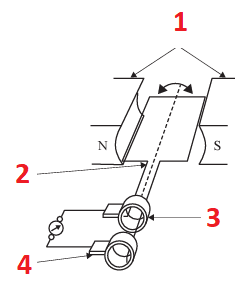
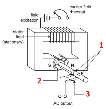
21
<p>What are the names + function for the 3 labeled components?</p>

What are the names + function for the 3 labeled components?

  1. Slip rings - electrical connectors on rotor

  2. Rotor coil - when rotates = magnetic field

  3. Brushes - electrical connectors to the slip ring and external circuit
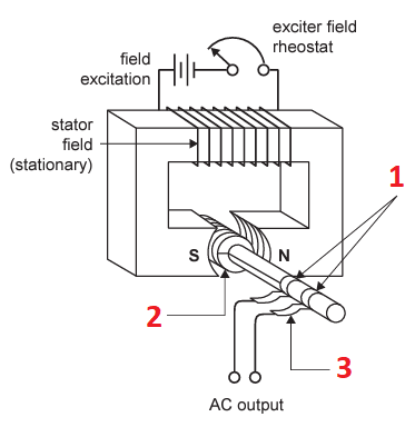
<ol><li><p>Slip rings - electrical connectors on rotor</p></li><li><p>Rotor coil - when rotates = magnetic field</p></li><li><p>Brushes - electrical connectors to the slip ring and external circuit</p></li></ol><p></p>
New cards
22
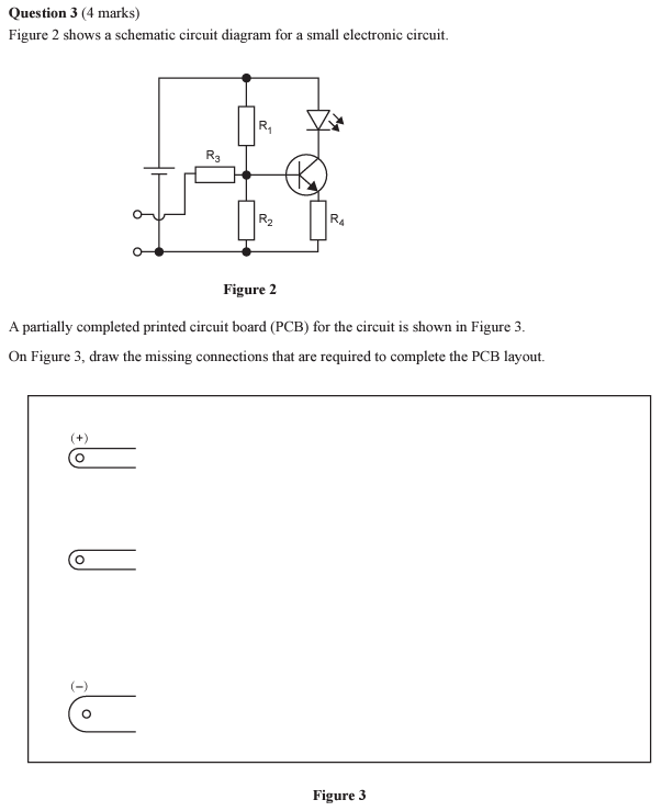
<p>(Click on the image to enlarge)</p><ol><li><p>What’s the one tricky bit of this question?</p></li><li><p>How do you work through it?</p></li></ol><p></p>

(Click on the image to enlarge)

  1. What’s the one tricky bit of this question?

  2. How do you work through it?

  1. The lower “started” diagram shows a + and -, so leave off the battery.

  2. Draw circles and lines on the top diagram - then copy below

(67% of students got 0 out of 4)
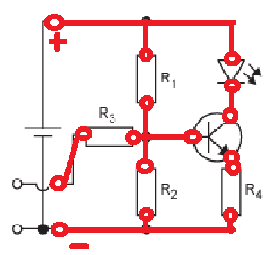
<ol><li><p>The lower “started” diagram shows a + and -, so leave off the battery. </p></li><li><p>Draw circles and lines on the top diagram - then copy below</p></li></ol><p>(67% of students got 0 out of 4)</p><p></p>
New cards
23
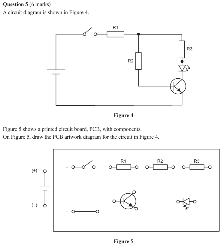
<p>(Click on the image to enlarge)</p><ol><li><p>How do you work through it?</p></li><li><p>What trick have they done in the past?</p></li></ol><p></p>

(Click on the image to enlarge)

  1. How do you work through it?

  2. What trick have they done in the past?

  1. Look at each wire between the components and ask yourself “where does it connect”. Usually 2-3 spots. Then, you draw that one, then start the next wire. (1 wire = 1 mark)

  2. They have flipped the answer box so you have to draw it flipped
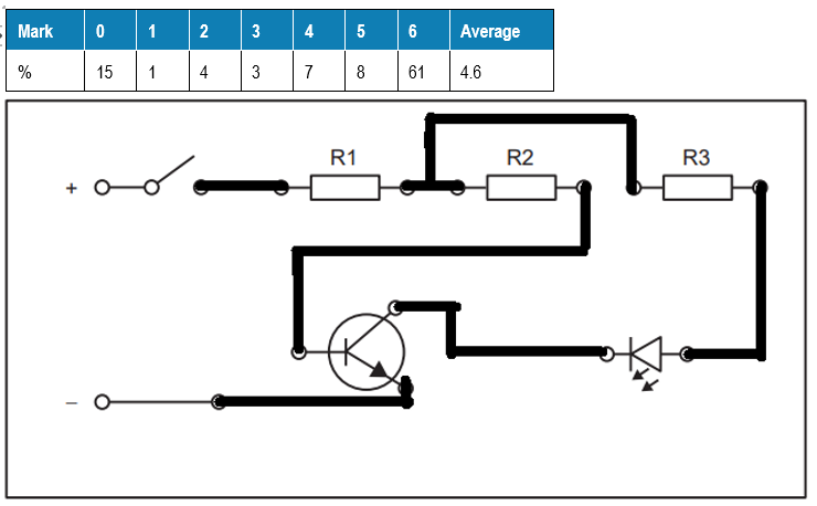
<ol><li><p>Look at each wire between the components and ask yourself “where does it connect”. Usually 2-3 spots. Then, you draw that one, then start the next wire. (1 wire = 1 mark)</p></li><li><p>They have flipped the answer box so you have to draw it flipped</p></li></ol><p></p>
New cards
24
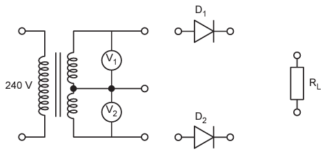
<p>(Click on the image to enlarge)</p><ol><li><p>What’s the one tricky bit of this question?</p></li><li><p>How do you complete the circuit?</p></li></ol><p></p>

(Click on the image to enlarge)

  1. What’s the one tricky bit of this question?

  2. How do you complete the circuit?

  1. It’s a rectifier and the middle wire is the ground

  2. The middle connects to one side of the resistor, the top and bottom to the other end (through the diodes)
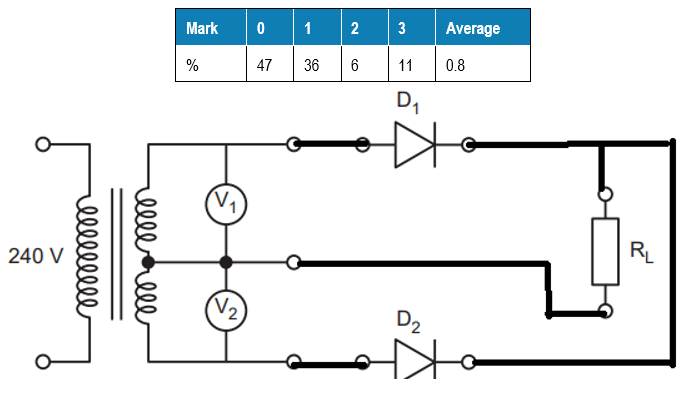
<ol><li><p>It’s a rectifier and the middle wire is the ground</p></li><li><p>The middle connects to one side of the resistor, the top and bottom to the other end (through the diodes)</p></li></ol><p></p>
New cards
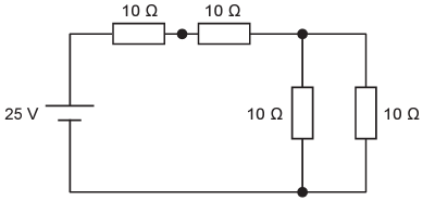
25
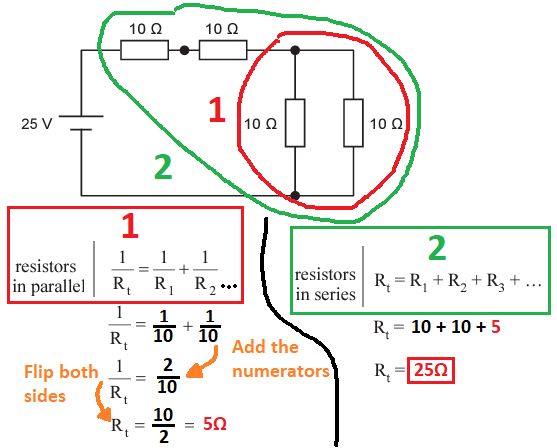
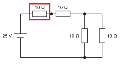
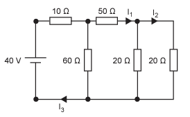
<p><strong>Resistance</strong> &gt; Current &gt; Voltage &gt; Power</p><p>How do you break down the process of calculating total resistance?</p><p></p>

Resistance > Current > Voltage > Power

How do you break down the process of calculating total resistance?

  1. Circle the parallel resistors (to calculate the total), then imagine it’s one resistor.

  2. All that’s left is three resistors in series

(full answer in image)
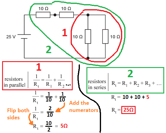
<ol><li><p>Circle the parallel resistors (to calculate the total), then imagine it’s one resistor.</p></li><li><p>All that’s left is three resistors in series</p></li></ol><p>(full answer in image)</p><p></p>
New cards
26
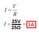
<p>Resistance &gt; <strong>Current</strong> &gt; Voltage &gt; Power</p><p>Once you have total resistance, which equation gives you the total current draw?</p><p></p>

Resistance > Current > Voltage > Power

Once you have total resistance, which equation gives you the total current draw?
knowt flashcard image
New cards
27
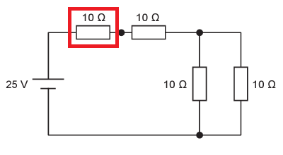
<p>Resistance &gt; Current &gt; <strong>Voltage</strong> &gt; Power</p><p>How do you work out the voltage drop across the circled resistor?</p>

Resistance > Current > Voltage > Power

How do you work out the voltage drop across the circled resistor?

  1. Voltage drops in series as a ratio of resistance (voltage division)

  2. The voltage division equation is shown in the image
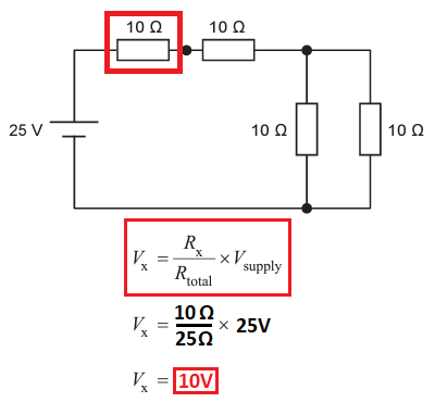
<ol><li><p>Voltage drops in series as a ratio of resistance (voltage division)</p></li><li><p>The voltage division equation is shown in the image</p></li></ol><p></p>
New cards
28
<p>Resistance &gt; Current &gt; Voltage &gt; <strong>Power</strong></p><ol><li><p>Once you have the the total current and voltage drop, how do you work out the power dissipation in the circled resistor?</p></li><li><p>Would a typical resistor you have used be able to handle this wattage?</p></li></ol><p></p>

Resistance > Current > Voltage > Power

  1. Once you have the the total current and voltage drop, how do you work out the power dissipation in the circled resistor?

  2. Would a typical resistor you have used be able to handle this wattage?

  1. Refer to the image

  2. Most resistors in Systems are 0.5W resistors (sometimes 1W or 2W but exam will specify). It would spectacularly melt and/or catch fire either way
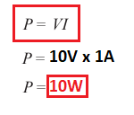
<ol><li><p>Refer to the image</p></li><li><p>Most resistors in Systems are 0.5W resistors (sometimes 1W or 2W but exam will specify). It would spectacularly melt and/or catch fire either way</p></li></ol><p></p>
New cards
29
<p>Resistance (2nd harder example)</p><p>How do you break down the process of calculating total resistance?</p><p>(all other calculations that follow are the same as before, so not repeated)</p>

Resistance (2nd harder example)

How do you break down the process of calculating total resistance?

(all other calculations that follow are the same as before, so not repeated)

  1. Circle the parallel resistors (to calculate the total), then imagine it’s one resistor.

  2. Circle the “combined” resistor with the one other in series, calculate the total.

  3. Circle the next two as parallel and calculate that

  4. Circle the final “combined” resistor with the last one (in series) and calculate that, which gets you the total.

(I drew another way to visualise the diagram if it helps)
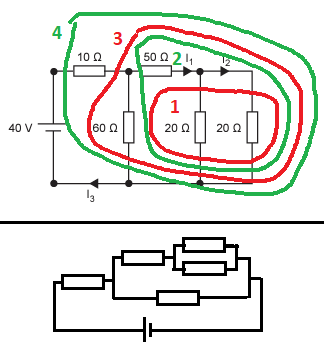
<ol><li><p>Circle the parallel resistors (to calculate the total), then imagine it’s one resistor.</p></li><li><p>Circle the “combined” resistor with the one other in series, calculate the total.</p></li><li><p>Circle the next two as parallel and calculate that</p></li><li><p>Circle the final “combined” resistor with the last one (in series) and calculate that, which gets you the total.</p></li></ol><p>(I drew another way to visualise the diagram if it helps)</p><p></p>
New cards
30
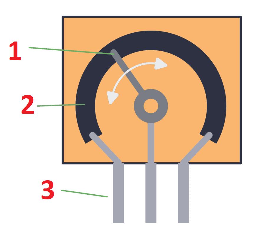
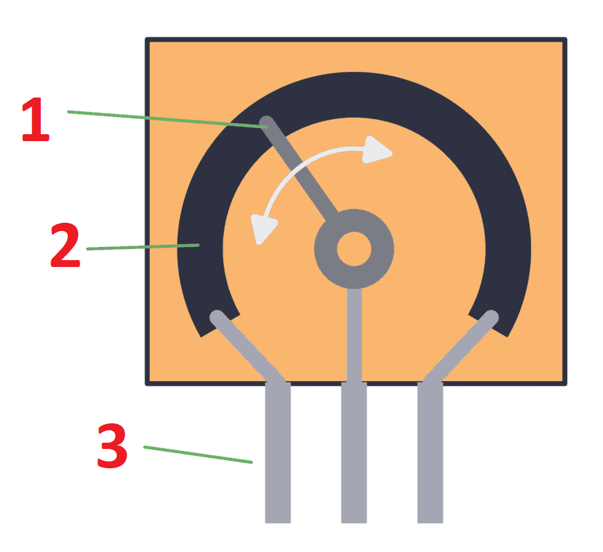
<ol><li><p>Which component is being represented here?</p></li><li><p><span style="color: #ff0000"><strong>(rare) </strong></span>Name the 3 labeled parts</p></li><li><p>Which pin is always connected when it use?</p></li></ol><p></p>
  1. Which component is being represented here?

  2. (rare) Name the 3 labeled parts

  3. Which pin is always connected when it use?

Potentiometer

  1. Wiper / Slider

  2. Resistive Strip

  3. Pins

The middle pin

<p>Potentiometer</p><ol><li><p>Wiper / Slider</p></li><li><p>Resistive Strip</p></li><li><p>Pins</p></li></ol><p>The middle pin</p><p></p>
New cards

Explore top notes

note Note
studied byStudied by 4 people
... ago
5.0(1)
note Note
studied byStudied by 16 people
... ago
5.0(1)
note Note
studied byStudied by 7 people
... ago
5.0(1)
note Note
studied byStudied by 13 people
... ago
5.0(1)
note Note
studied byStudied by 25 people
... ago
5.0(1)
note Note
studied byStudied by 153 people
... ago
4.7(7)
note Note
studied byStudied by 6 people
... ago
5.0(1)

Explore top flashcards

flashcards Flashcard (20)
studied byStudied by 2 people
... ago
5.0(1)
flashcards Flashcard (110)
studied byStudied by 17 people
... ago
5.0(1)
flashcards Flashcard (45)
studied byStudied by 5 people
... ago
5.0(1)
flashcards Flashcard (20)
studied byStudied by 1 person
... ago
5.0(1)
flashcards Flashcard (33)
studied byStudied by 53 people
... ago
5.0(1)
flashcards Flashcard (100)
studied byStudied by 8 people
... ago
5.0(1)
flashcards Flashcard (32)
studied byStudied by 39 people
... ago
5.0(3)
flashcards Flashcard (36)
studied byStudied by 206 people
... ago
5.0(1)
robot