Module 1: Networking Fundamentals
1/124
Earn XP
Description and Tags
Basahin nyo na lang yung chart ng special addresses sa pages 73 to 75
Name | Mastery | Learn | Test | Matching | Spaced |
|---|
No study sessions yet.
125 Terms
Open Systems Interconnect/ion
created in 1984 by ISO (International Organization for Standardization)
ISO
International Organization for Standardization
Reference Model
a theoretical foundation for understanding network communication
OSI REFERENCE MODEL
It is divided into seven layers that work together to carry out specialized network functions, allowing for a more systematic approach to networking
Physical Layer
Responsible for moving individual bits from one device to the next device.
Physical Layer
When receiving data, this layer will get the signal received and convert it into 0s and 1s and send them to the Data Link layer
Data Link Layer
Responsible for moving frame from one hop to next hop.
Data Link Layer
it is the responsibility of this layer to transmit it to the Host using its MAC address.
Network Layer
Responsible for delivery of individual packet from source to destination.
Network Layer
The sender and receiver's IP address are placed in the header by this layer
Transport Layer
Responsible for process to process delivery.
Transport Layer
This layer accepts the message from the (session) layer and breaks the message into smaller units.
Session Layer
It stablish, maintain, synchronize, and terminate the interaction between sender and receiver.
Presentation Layer
Take care of syntax and semantics of the information exchange between two communication system.
Application Layer
Responsible for providing services to the user.
Bit, Symbol
PDU (Protocol Data Unit) of the Physical Layer
Frame
PDU (Protocol Data Unit) of the Data Link Layer
Packet
PDU (Protocol Data Unit) of the Network Layer
Segment, Datagram
PDU (Protocol Data Unit) of the Transport Layer
Data/ Message
PDU (Protocol Data Unit) of the Session, Presentation, and Application Layer
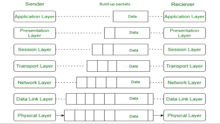
Data flows through the OSI model in a step-by-step process:
Application Layer: Applications create the data.
Presentation Layer: Data is formatted and encrypted.
Session Layer: Connections are established and managed.
Transport Layer: Data is broken into segments for reliable delivery.
Network Layer: Segments are packaged into packets and routed.
Data Link Layer: Packets are framed and sent to the next device.
Physical Layer: Frames are converted into bits and transmitted physically.
End Device
a network-enabled hardware device that serves as either the source or destination of data transferred through a network.
End Device
workstation, laptop, desktop computer, printer, scanner, tablet, or cell phone
Intermediary Device
the ones that connect end devices and allow data transmission on a network.
Intermediary Device
hubs, bridges, switches, routers, repeaters, gateways, firewalls, or access points
Client – Server Network
Computer networks that employ a dedicated computer to store data, manage/provide resources, and control user access (server).
Client – Server Network
follows request-response pattern
Server
connects all the other computers in the network by acting as a hub.
Server
a computer or system that provides resources, data, services, or programs to other computers, known as clients, over a network
Client
any computer hardware or software device that requests access to a service provided by a server.
Client
typically seen as the requesting program or user in a client-server architecture
Peer-to-Peer Network
Defined as a network where all nodes, known as peers, interact cooperatively without a distinction between clients and servers, sharing resources and self-organizing into network topologies without the need for a centralized server
Peer
a node that provides the same functionality as another
Peer
a device that can function as a client or a server
IEEE
Institute of Electrical and Electronics Engineers
IEEE (Institute of Electrical and Electronics Engineers) 802
A collection of networking standards that cover the physical and data link layer specifications for technologies such as Ethernet and wireless
IEEE 802.1
Higher Layer LAN Protocols Working Group
IEEE 802.3
Ethernet (copper/ fiber optic)
IEEE 802.11
Wireless LAN (WLAN) & Mesh (Wi-Fi certification)
IEEE 802.15
Wireless PAN (Bluetooth/ infrared)
Personal Area Network
PAN
connects electronic devices within a user's immediate area
Bluetooth and Infrared
IEEE 802.5 – Token Ring
a data link for a local area network in which all devices are connected in a ring or star topology and pass one or more tokens from host to host.
token
is passed between nodes to authorize that node to communicate
is the symbol of authority for control of the transmission line.
Multistation access unit (MSAU)
Intermediary device for token ring.
IEEE 802.3
Discovered in 1980 by Robert Metcalfe
Standardized in 1983
LAN
Local Area Network
collection of devices connected together in one physical location, such as a building, office, or home
Ethernet and WiFi
MAN
Metropolitan Area Network
a computer network that interconnects users with computer resources in a geographic region of the size of a metropolitan area
Backbone network/ Access Network
WAN
Wide Area Network
a network that extends over a large geographic area, connecting multiple LANs
Internet
Switch
only used for interconnecting devices
Router
necessary for an Internet connection
Router
refers to networking equipment moving data packets from one computer network to another.
Router
It operates at layer 3 of the Open Systems Interconnection stack and allows several devices to use the same internet connection.
Router
It also manages traffic between the computer networks by forwarding data packets to their specified Internet Protocol addresses
Router
use dynamic routing algorithms to determine the best path across the internetwork, thus minimizing traffic load
Router
they are interoperable with other networking devices, such as modems, one may use routers in together with those other devices.
Router
They are relatively slow as they process data packets at three layers.
Switch
It works at layer 2 of the Open Systems Interconnection model, which is the data link layer.
It receives data packets and sends them to the correct device.
Switch
When a data packet enters this, it reads the header to find its Media Access Control address and determine its destination
Switch
Provide faster data transfer rates, resulting in better network performance.
They can establish a direct connection with workstations.
Switch
They are expensive.
Broadcast/ multicast traffic can be problematic.
Switch
direct path
improved speed
scalability
Router
connect to different networks (interoperable)
firewall and routing
IP Addressing
Routing
Logical Addressing
Main Functions of Network layer
Hostname
a unique label assigned to a device connected to a computer network
A unique name given to a device on the network
Physical address
A MAC (Media Access Control) address identifies network devices locally
Logical address
IP addresses are primarily used to identify a node's connectivity to a network.
IP Address
A unique number assigned to a device on a network
MAC Address
A unique hardware address of the network interface
IPV4
32 bits in length and gives us a maximum of 232 addresses
IP Address
two parts: a network identifier and a host identifier.
Subnet masks
clarify which part of the address is the network ID and which is the host ID.
default gateway
is the path used to pass information when the device doesn't know where the destination is
Domain Name System (DNS)
is the phonebook of the Internet, it is managing the mapping between names (website) and numbers (IP address)
Domain Name System (DNS)
servers translate requests for names into IP addresses, controlling which server an end user will reach when they type a domain name into their web browser
Binary notation
01110101.10010101.00011101.00000010
Dotted-decimal notation
117.149.29.2
Octet
a unit of digital information in computing and telecommunications that consists of eight bits
Classful Addressing
An IPv4 addressing architecture that divides addresses into five groups (class)
Each class had a fixed range of addresses and a default subnet mask.
Class A
the first bit of the first octet is always '0'.
The first 8 bits or the first octet denote the network portion and the rest 24 bits or the 3 octets belong to the host portion.
1.0.0.0 to 126.255.255.255
the actual range of class A addresses
Class B
the first octet would always start with '10'.
The first 16 bits or the first two octets denote the network portion and the remaining 16 bits or two octets belong to the host portion.
128.0.0.0 to 191.255.255.255
class B addresses range
Class C
the first octet would always start with '110'.
The first 24 bits or the first three octets denote the network portion and the rest 8 bits or the remaining one octet belong to the host portion.
192.0.0.0 to 223.255.255.255
class C addresses range
Class D
a specific type of IP address labeling a network location that is used to multicast data packets within a network
multicast
is a type of group communication where data transmission is addressed to a group of destination computers simultaneously
224.0.0.0 to 239.255.255.255
Class D range
Class E
addresses are reserved for research purposes and future use.
The first octet in a class E address starts with '1111'.
240.0.0.0 to 255.255.255.255
class E addresses range
Internet Engineering Task Force (IETF)
is a standards organization for the Internet and is responsible for the technical standards that make up the Internet protocol suite.
CIDR
Unicast
a one-to-one transmission from one point in the network to another point
Multicast
a type of group communication where data transmission is addressed to a group of destination computers simultaneously
Multicast
can be one-to-many or many-to-many distribution
Network address
used to distinguish a network that has its own hosts and addresses (first address)
Broadcast addresses
used to transmit to all devices connected to a multiple-access communications network (last address)
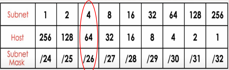
Classless Addressing
CIDR was introduced to address the shortcomings of classful addressing and to allow more efficient allocation of IP addresses.
CIDR
Classless Inter-Domain Routing
how IP addresses are allocated
prefix length
specifies the number of bits in the network portion of the address, offering more flexibility.
Variable-Length Subnet Mask (VLSM)
technique, which changes the ratio between network and host address bits in an IP address
allows networks to use subnet masks of varying lengths, accommodating networks of different sizes within the same address space.