CHAPTER 7: TOOTH MORPHOLOGY AND ACCESS CAVITY PREPARATION (part I)
1/82
Earn XP
Description and Tags
from book
Name | Mastery | Learn | Test | Matching | Spaced | Call with Kai |
|---|
No study sessions yet.
83 Terms
main objectives of root canal therapy
thorough shaping and cleaning of all pulp spaces
complete obtura- tion of these spaces with an inert filling material
Diagnostic measures in locating root canal orifices
multiple pretreatment radiographs or cone beam CT
examining the pulp chamber floor with a sharp explorer
troughing grooves with ultrasonic tips
staining the chamber floor with 1% methylene blue dye
sodium hypochlorite “champagne bubble” test
visualizing pulp chamber anatomy & root canal bleeding points
recommended for effective cleaning and drying of the pulp chamber floor before visual inspection of the canal system
17% aqueous ethylenediami-netetraacetic acid (EDTA)
95% ethanol (using the Stropko irrigator fitted with a 27-gauge notched irrigating needle)
dental operating microscope (DOM)
an important aid for locating root canals
introduced into end- odontics to provide enhanced lighting and visibility
enhances the clinician’s ability to remove dentin with great precision, thereby minimizing procedural errors
improves the clinician’s ability to locate and negotiate canals
by magnifying and illuminating the grooves in the pulpal floor and by distinguishing the color differences of the dentin of the floor and walls
sodium hypochlorite (NaOCl)
allowing this to remain in the pulp chamber may help locate a calcified root canal orifice
tiny bubbles may appear in the solution, indicating the position of the orifice
root canal system
The entire space in the dentin where the pulp is housed
The outline of this system corresponds to the external contour of the tooth
factors potentially modify its dimensions such as:
physiologic aging
pathosis
occlusion
production of secondary/tertiary dentin & cementum
two portions of root canal system
pulp chamber — in the anatomic crown of the tooth
pulp or root canals — found in the anatomic root
Other features of root canal system
pulp horns
accessory canals
lateral canals
furcation canals
canal orifices
apical deltas
apical foramina
root canal
begins as a funnel-shaped canal orifice
generally at or just apical to the cervical line and ends at the apical foramen, which opens onto the root surface at or within 3 mm from the center of the root apex
Nearly all root canals are curved, particularly in a faciolingual direction
These curva- tures may pose problems during shaping and cleaning proce- dures because they are not evident on a standard facial radiograph.
Angled views are necessary to determine their presence, direction, and severity
A curvature may be a gradual curve of the entire canal or a sharp curvature near the apex
Double S-shaped canal curvatures also can occur.
In most cases the number of root canals corresponds to the number of roots; however, an oval root may have more than one canal
Accessory canals
are minute canals that extend in a horizontal, vertical, or lateral direction from the pulp to the periodontium
In 74% of cases they are found in the apical third of the root, in 11% in the middle third, and in 15% in the center of the root apex.
contain connective tissue and vessels but do not supply the pulp with sufficient circulation to form a collateral source of blood flow
formed by the entrapment of periodontal vessels in Hertwig’s epithelial root sheath during calcification
they are sig- nificant because they serve as avenues for the passage of irri- tants, primarily from the pulp to the periodontium
furcation canals
Accessory canals may also occur in the bifurcation or trifurcation of multi-rooted teeth
form as a result of the entrapment of periodontal vessels during the fusion of the diaphragm, which becomes the pulp chamber floor
occur in three distinct pattern for mandibular molars
4 to 720 μm
the diameter of furcation openings in mandibular molars according to scanning electron microscopy (SEM)
none to more than 20 per specimen
range of number of furcation canals
Mandibular teeth
have a higher incidence of foramina involving both the pulp chamber floor and the furcation surface
3 distinct patterns accessory canals occur in MN first molars
single furcation canal extends from the pulp chamber to the intraradicular region
lateral canal extends from the coronal third of a major root canal to the furca- tion region (80% extend from the distal root canal)
have both lateral and furcation canals.
basic requirement for endodontic success.
diagnosis and treatment planning
knowledge of common root canal morphology & its frequent variations
the exception rather than the rule
a root with a tapering canal & a single foramen
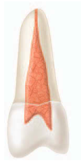
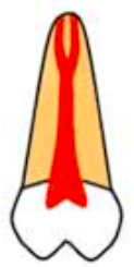
Vertucci’s classification type I
A single canal extends from the pulp chamber to the apex (1)
Vertucci’s classification type II
Two separate canals leave the pulp chamber and join short of the apex to form one canal (2-1)

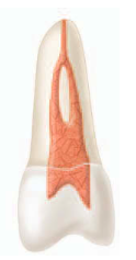
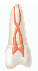
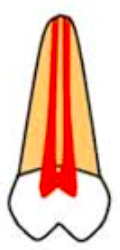
Vertucci’s classification type III
One canal leaves the pulp chamber and divides into two in the root; the two then merge to exit as one canal (1-2-1)
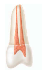
Vertucci’s classification type IV
Two separate, distinct canals extend from the pulp chamber to the apex (2)
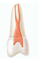
Vertucci’s classification type V
One canal leaves the pulp chamber and divides short of the apex into two separate, distinct canals with separate apical foramina (1-2)
Vertucci’s classification type VI
Two separate canals leave the pulp chamber, merge in the body of the root, and redivide short of the apex to exit as two distinct canals (2-1-2)
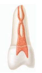
Vertucci’s classification type VII
One canal leaves the pulp chamber, divides and then rejoins in the body of the root, and finally redivides into two distinct canals short of the apex (1-2-1-2).
Vertucci’s classification type VIII
Three separate, distinct canals extend from the pulp chamber to the apex (3).

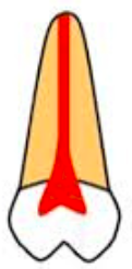
Weine’s Classification type I
(Single canal, single exit) 1
Weine’s Classification type II
(Two separate canals, merging to one exit) 2-1
Weine’s Classification type III
(Two canals throughout, twO separate exits) 2-2
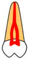
Weine’s Classification type IV
(One single canal, splitting into two exits) 1-2
orifice
If only one of this is found and it is not in the center of the root, another one probably exists
The closer they are, the greater the chance the two canals join at some point in the body of the root
as the distance between of this in a root increases, the greater the chance is that the canals will remain separate.
The more separation between orifices the less the degree of canal curvature
3 anatomic & histologic landmarks where classic concept of apical root anatomy is based
minor foramen / apical constriction (AC)
cementodentinal junction (CDJ)
major foramen / apical foramen (AF)
apical constriction (AC)
narrowest part of the canal
tapering 0.5-1.5mm coronal to the apical foramen
generally is considered the part of the root canal with the smallest diam- eter
also is the reference point clinicians use most often as the apical termination for shaping, cleaning, and obturation
Pulp blood vessels are narrow at the AC, which makes success- ful treatment of inflammation in the canal difficult
Posttreat- ment discomfort generally is greater when this area is violated by instruments or filling materials, and the healing process may be compromised.
cementodentinal junction (CDJ)
approximately 1 mm from the apical foramen
the point in the canal where cementum meets dentin
it is the point where pulp tissue ends and periodontal tissues begin
The location in the root canal varies considerably
It generally is not in the same area as the apical constriction
considered just a variable junction at which two histologic tissues meet in the root canal
apical foramen (AF)
circumference or rounded edge like a funnel or crater, that differentiates the termination of the cemental canal from the exterior surface of the root
From apical constriction, the canal widens as it exits the root at this point
does not normally exit at the anatomic apex but rather is offset 0.5 to 3 mm
funnel shaped / hyperbolic / shape of a morning glory
The space between the major and minor diameters has been described as ___
mean distance between the major and minor apical foramen
0.5 mm in a young person
0.67 mm in an older individual
—distance is greater in older individuals because of the buildup of cementum
diameter of the foramen
502 μm in individuals 18-25 years of age
681 μm in those over age 55
—which demonstrates the growth of apical foramen with age
diameter of the canal at the CDJ
353 μm for the central incisors
292 μm for the lateral incisors
298 μm for the canines
maxillary premolars
had the most and the largest accessory foramina (mean value, 53 μm) and the most complicated apical morphologic makeup.
—mandibular premolars had strik- ingly similar characteristics, a possible reason why root canal therapy may fail in premolar teeth
termination points
1 mm from the apex — no bone or root resorption has occurred
1.5 mm from the apex — only bone resorption has occurred
2 mm from the apex — both bone and root resorption have occurred
may cause a severe inflammatory reaction
Sealer or gutta-percha (or both) in the periradicular tissues, lateral canals, and
apical ramifications
Successful treatment depends on:
the anatomy of the root canal system, the dimensions of the canal walls, and the final size of enlarging instruments.
maxillary first molar
has a very complicated canal shape at the apical limit and that this anatomy makes shaping, cleaning, and obturation difficult, particularly in the MB-1 and distobuc- cal canals.
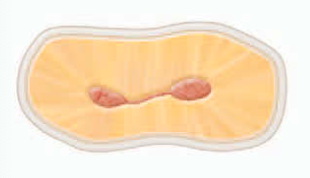
isthmus
a narrow, ribbon-shaped communication between two root canals that contains pulp or pulpally derived tissue
must be found, prepared, and filled during surgery, because they can function as bacterial reservoirs
Any root with two or more canals may have this so this should be suspected whenever multiple canals are seen on a resected root surface
methylene blue dye
used to aid visualization of the outline of the resected root surface and thus detection of an isthmus
objectives of access cavity preparation
(1) to remove all caries,
(2) to conserve sound tooth structure,
(3) to completely unroof the pulp chamber,
(4) to remove all coronal pulp tissue (vital or necrotic),
(5) to locate all root canal orifices,
(6) to achieve straight- or direct-line access to the apical foramen or to the initial curvature of the canal
(7) to establish restorative margins to minimize marginal leakage of the restored tooth
properly prepared access cavity creates:
a smooth, straight-line path to the canal system and ultimately to the apex, or position of the first curvature
allows complete irrigation, shaping and cleaning, and quality obturation
Ideal access results in straight entry into the canal orifice, with the line angles forming a funnel that drops smoothly into the canal(s)
Straight line access
provides the best chance of debridement of the entire canal space and reduces the risk of file breakage
isthmus classifications type I
an incomplete isthmus
it is a faint communication between two canals.
isthmus classifications type II
characterized by two canals with a definite connection between them (complete isthmus).
isthmus classifications type III
a very short, complete isthmus between two canals.

isthmus classifications type IV
complete or incomplete isthmus between three or more canals

isthmus classifications type V
marked by two or three canal openings without visible connections.
indicates the location of the line angles
Projection of the canal center line to the occlusal surface of the tooth
step in preparing an access cavity
visualization of the position of the pulp space in the tooth
Evaluation of the Cementoenamel Junction and Occlusal Anatomies
Preparation of the Access Cavity Through the Lingual and Occlusal Surfaces
Removal of All Defective Restorations and Caries Before Entry Into the Pulp Chamber
Removal of Unsupported Tooth Structure to prevent tooth fracture.
Delay of Dental Dam Placement Until Difficult Canals Have Been Located and Confirmed
Location, Flaring, and Exploration of All Root Canal Orifices
Inspection of the Pulp Chamber, Using Magnification and Adequate Illumination
Tapering of Cavity Walls and Evaluation of Space Adequacy for a Coronal Seal
cementoenamel junc- tion (CEJ)
the most important anatomic landmark for determining the location of pulp chambers and root canal orifices.
importance of Diag- nostic radiographs
help the clinician estimate the position of the pulp chamber,
the degree of chamber calcification,
the number of roots and canals
the approximate canal length
—Palpation along the attached gingiva aids the determination of root location and direction.
results when passage of instru- ments down the canal is not guided by the walls of the root canal
treatment errors
root perforation
misdirection of an instrument from the main canal (ledge formation)
instru- ment separation
creation of an incorrect canal shape (apical transportation)
Micro-Openers
excellent instruments for locating canal orifices when a dental dam has not been placed.
flexible, stainless steel hand instru- ments have #.04 and #.06 tapered tips
have offset handles that provide enhanced visualization of the pulp chamber.
—dental dam must be placed once the roof of the pulp chamber has been penetrated and the canals identified.
endodontic explorer
a sharp instrument used to locate canal orifices and to determine their angle of departure from the pulp chamber
Congealed pulp tissue
may form a collagen plug that blocks the apex, preventing complete shaping and cleaning.
reducing the risk of bacterial contamination of the canal system
composite, glass ionomer, and mineral trioxide aggregate
Round carbide burs #2, #4, and #6
used extensively in the preparation of access cavities.
They are used to remove caries and to create the initial external outline shape.
They also are useful for penetrating through the roof of the pulp chamber and for removing the roof
fissure carbide and diamond round-end burs
can be used for some of the axial wall extensions of the access cavity preparation.
can be used to level off cusp tips and incisal edges, which are used as reference points for the working length determination.
However, when these burs are used for this purpose by inexperienced clinicians, their cutting ends can gouge the pulp floor and axial walls
—Fissure carbide and diamond burs with safety tips (i.e., noncutting ends) safer choices for axial wall extensions. They can be used to extend and favorably orient the axial walls of the pulp chamber. Because they have no cutting end, the burs can be allowed to extend to the pulp floor
Round diamond burs (#2 and #4)
needed when endodontic access must be made through porce- lain or ceramometal restorations
—Diamond burs are less trau- matic to porcelain than carbide burs and are more likely to penetrate the porcelain without cracking or fracturing it
Gates-Glidden burs
used during shaping and cleaning to enter the canal(s) easily
used to flare or enlarged and blend the orifices into the axial walls of the access cavity
This process permits the intracanal instruments
starting with smaller sizes and progressing to the larger sizes
DG-16 endodontic explorer
used to identify canal orifices and to determine canal angulation.
JW-17 endodontic explorer
serves the same purpose as DG-16 endodontic explorer
its thinner, stiffer tip can be useful for identifying calcified canals.
useful for detecting any remaining pulp chamber roof, particularly in the area of a pulp horn
endodon- tic spoon
used to remove coronal pulp and carious dentin
fine Ultrasonic tips
used to trough and deepen developmental grooves to remove tissue and explore for canals
are smaller than conventional round burs
their abrasive coatings allow clinicians to sand away dentin and calcifications conservatively when exploring for canal orifices.
Evaluation of straight-line access
Insert the largest file that fits passively to the apical foramen or first canal curvature.
Measure internal canal length from a pretreatment periapical radiograph.
Gently insert and withdraw the file to feel for binding or deflection.
If deflection occurs:
Reassess lingual shoulder removal.
Avoid prematurely extending the incisal edge.
If lingual shoulder is adequate but the file still binds, extend the incisal wall until straight-line access is achieved.
Final incisal wall position is determined by:
Complete removal of pulp horns
Achievement of straight-line access
Access preparation
#2 round bur for premolars
#4 round bur for molars
—Penetrate 1 mm into dentin
Shape considerations
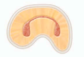
Premolars: oval, widest buccolingually
Molars: initially oval, widest:
Maxillary molars: buccolingual
Mandibular molars: mesiodistal
Final molar outline
triangular (three canals) or rhomboid (four canals), with corners determined by canal orifice positions.
Penetration angles of premolars
parallel to the long axis of the root in both mesiodistal and buccolingual directions to avoid gouging or perforation, as roots are often tilted relative to the occlusal plane.
Penetration angles of molars
toward the largest canal, since the pulp chamber is usually widest just above that orifice:
Maxillary molars → palatal canal
Mandibular molars → distal canal
“mouse hole” effect
an orifice extends onto an axial wall indicating internal underextension and impeding straight-line access.
internal impediments to straight-line access in posterior teeth
cervical dentin bulges and the natural coronal canal constriction.
Cervical dentin bulges
are dentin shelves that may overhang canal orifices, restricting access and accentuating canal curvatures.
Removal methods for Cervical dentin bulges
Safety-tip diamond or carbide burs
Gates-Glidden burs
Instruments are placed at the orifice level and leaned toward the bulge to remove overhanging dentin.
Removal methods for Coronal flaring:
Use Gates-Glidden burs in a sweeping upward motion with lateral pressure away from the furcation.
Alternatively, #10 or #12 tapered NiTi rotary files can shape the upper canal.