module 3 - assembly language
 Call Kai
 Learn
Learn Practice Test
 Spaced Repetition
 Match
Match Flashcards
 Knowt Play
1/87

There's no tags or description
Looks like no tags are added yet.
Name | Mastery | Learn | Test | Matching | Spaced | Call with Kai | Chat |
|---|
No analytics yet
Send a link to your students to track their progress
88 Terms
Programming Languages:
A programming language is a set of instructions used by humans to communicate with computers.
they enable the performance of specific tasks
they solve problems through code and algorithms.
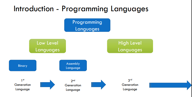
Programming Languages — Natural Languages:
Natural languages refer to the human languages, i.e., the languages that people speak such as English, Italian, French and Chinese.
The problem with natural languages is that they are ambiguous.
Programming Languages — Formal Languages:
Formal languages are languages that are designed by people for specific applications.
E.g. the Backus Naur Form (BNF) notation.
The advantage of formal languages when compared to natural languages is that they are less ambiguous.
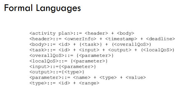
Programming Languages — Formal Languages; High Level Languages:
Use English-like statements, therefore easier for a programmer to understand and use.
COMPILER or INTERPRETER
Needed to translate instructions from a high-level language to machine code
E.g.:
Python: print("Hello World")
Java: System. out. println("arbitrary text");
C#: Console. WriteLine("Hello World!");
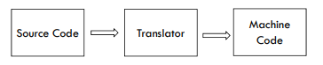
Programming Languages — Translators:
A translator takes a program written in source code as input and converts it into a program in target language as output.
Three types of translators:
1. Compiler
2. Interpreter
3. Assembler
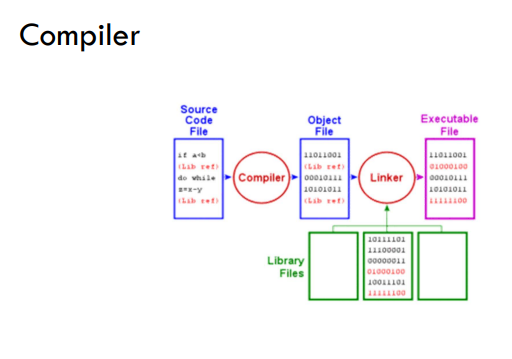
Programming Languages — Translators; Compiler:
Compilers are used to translate a program written in a high-level language into machine code (object code).
1. Compilers translate the source code all in one go.
2. Once compiled, the translated program file can then be directly used by the computer and is independently executable file of machine code (.exe).
3. Compiling may take some time, but the translated program can be used again and again without the need for recompilation.
4. Error reports are produced once the entire program is compiled.
Programming Languages — Translators; Interpreter:
Interpreter programs read, translate and execute one statement at a time from a high-level language program.
1. Stops when a line of code is reached that contains an error.
2. Used during the development of a program as they make debugging easier as each line of code is analysed and checked before execution.
3. Interpreted programs will launch immediately, but your program may run slower than a complied file as it is interpreted every time it is launched.
4. No executable file is produced.
Programming Languages — High Level Languages:
Things to consider…
1. Machine independent
NOT machine oriented
a program written for one machine will run on any other machine for which the appropriate compiler or interpreter is available.
A high-level statement may result in many low-level instructions.
Programming Languages — Low-Level Languages:
Very difficult for a programmer to use.
Machine oriented/dependent
A program written for one machine will probably not work on any other type of machine
E.g.: Assembly Language
Programming Languages — Machine Code:
The language which the computer understands
Only consists of 0s and 1s – Binary Number System.
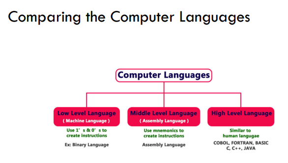
Compare the Computer Languages:
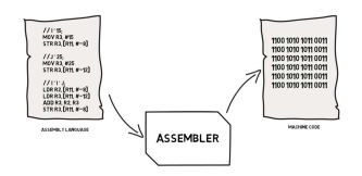
Programming Languages — Assembly Language:
Assembly Language is an example of low-level language
uses mnemonics instead of 0s and 1s
somewhat easier to use by programmers.
requires an ASSEMBLER
Needed to translate instructions from Assembly Language to machine code.
Programming Languages — Mnemonics:
A mnemonic is a symbolic code or abbreviation (short words) used to represent complex or low-level instructions. They are more human-readable and easier to remember than 1s & 0s.
E.g.: MOV AL, 54H
Programming Languages — Assembler:
An assembler is a software tool in computer programming that translates assembly language code into machine code.
1. Assembly Language is human-readable
2. Machine code is only understandable and executable by a computer's central processing unit (CPU).
3. Once assembled, the program file can be used again and again without re-assembly (executable).
Programming Languages — Machine Dependent:
Assembly language, unlike high-level languages, is machine-dependent i.e. depends on the architecture of the system.
1. Each microprocessor has its own set of instructions, that it can support.
2. During these lessons the IBM-PC assembly language for the Intel 8086 instruction set.
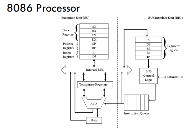
Programming Languages — 8086 Processor:
The 8086 microprocessor (designed by Intel in 1976) has a total of eight 16-bits general purpose registers. General purpose registers are used to store temporary data, depending on the current operation being executed by the microprocessor. These registers can be classified into three main categories depending on their functionality: Data Registers, Pointer Registers, and Index Registers.
Programming Languages — x86 V.S. x64:
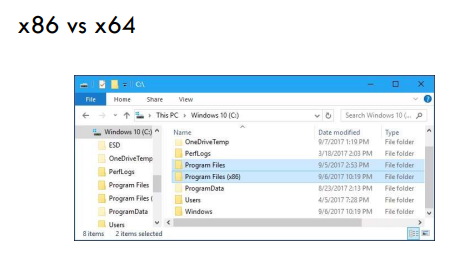
The term “x86” is generally used to denote any 16-bit or 32-bitarchitecture predating the 64-bit standard.
On the other hand “x64” is the standard notation for 64-bit releases.
The “Program Files (x86)” directory is thus reserved for applications using a 16-bit or 32-bit CPU.
Intel Pentium 4 (Released Year 2000) – 32bit
Intel Pentium D (Released Year 2005) – 64bit
AMD Ryzen 9 7950X AM5 (Released Year 2022) – 64bit
The bit rating of a CPU dictates the maximum size of internal registers that can be addressed by that same CPU.
Therefore a 64-bit CPU has registers that can store 64 bits of data, i.e. 2 64 = 18,446,744,073,709,551,616 addresses
Programming Languages — Advantages of Assembly Language:
It requires less memory and execution time
It is suitable for hardware-specific complex jobs
It is suitable for time-critical jobs
It is most suitable for writing interrupt service routines (ISR).
Instruction Format:
An instruction: a sequence of binary bits (0 Or 1) contained in a machine instruction that defines the layout of the instruction.
An instruction set: the set of instructions that a particular CPU can execute.
instruction set varies from one processor to another (8086 processor)
Instruction Format — Opcode and Operand:
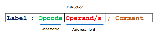
An instruction in an instruction set can be defined by:
Opcode (short for operation code):
compulsory
contains the mnemonic that we are using for a particular operation. (e.g.: SUB, MOV & ADD)
Operand/s:
are (addresses of) the data the opcode will manipulate.
E.g.: init : MOV AX, 23; move value 23 decimal into register AX
Label:
optional
used to identify a point within a program to which execution may jump.
used in symbolic addressing
Comments:
optional • ignored when the code is assembled (translated to machine code)
Some examples of 8086 instructions:
MOV AX,5 ; move decimal number to register AX
MOV AX,00011010 ; move binary number to register AX
MOV AX,1AH ; move hexadecimal number to register AX
Number Systems used in Assembly Languages:
Binary (Base-2):
Binary is the fundamental number system used in computers.
It consists of only two digits, 0 and 1.
In assembly language, you often work with binary numbers when dealing with individual bits and performing bitwise operations.
E.g.:
MOV AX, 00011010 ; Binary number (suffix 'b' or 'B' often used to denote binary)
MOV AX, 00011010b;
Decimal (Denary) (Base-10):
Decimal is the number system most familiar to humans, with digits ranging from 0 to 9.
In assembly language, you can represent decimal numbers directly without any special notation.
E.g. MOV AX, 26 ; Decimal number
Hexadecimal (Base-16):
Hexadecimal is commonly used in assembly language programming because it provides a compact representation of binary data.
It uses digits 0-9 and letters A-F to represent values from 0 to 15.
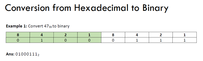
Hexadecimal numbers are represented as a 4-bit binary number.
MOV AX, 1AH ; Hexadecimal number (suffix 'H' often used to denote hexadecimal)
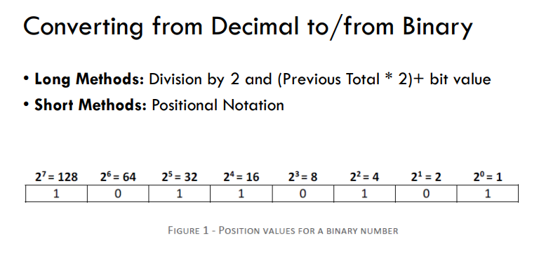
Converting from Decimal to/from Binary:
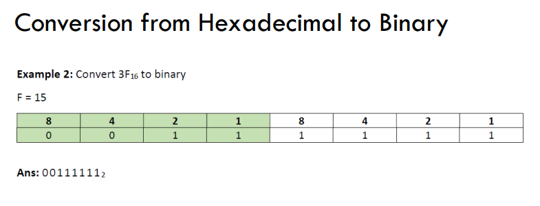
Conversion from Hexadecimal to Binary:
Conversion from Hexadecimal to Binary:
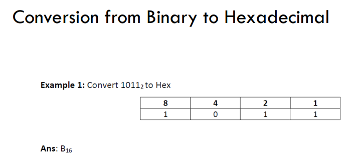
Conversion from Binary to Hexadecimal:
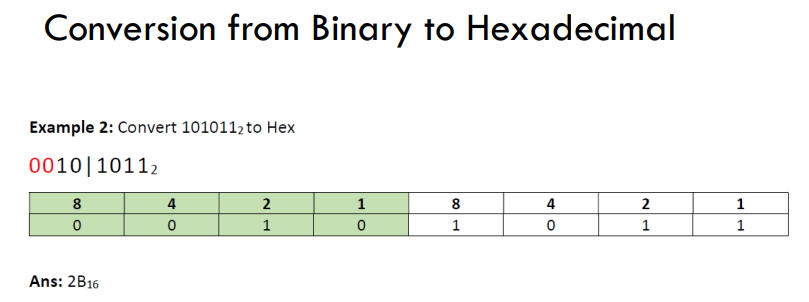
Conversion from Binary to Hexadecimal:
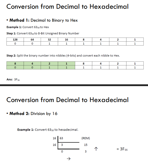
Conversion from Decimal to Hexadecimal:
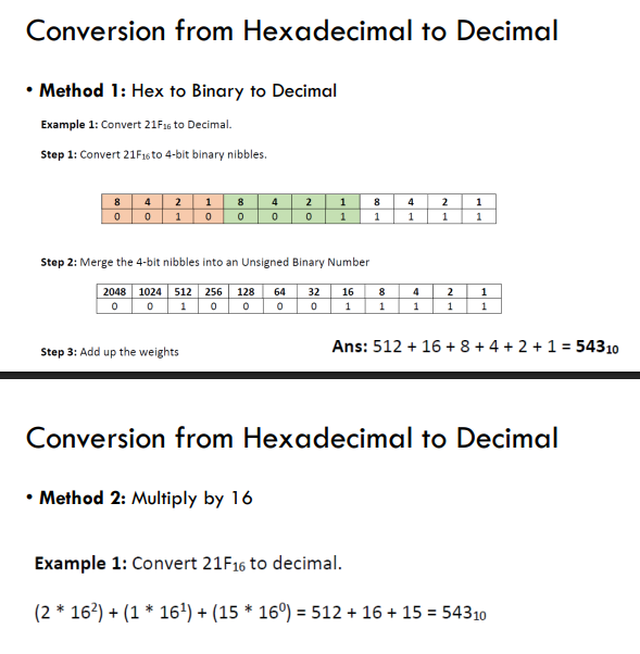
Conversion from Hexadecimal to Decimal:
Registers:
Temporary storage locations within the CPU for the data that is currently being processed.
1. Special Purpose Registers
General Purpose Registers
E.g. of Assembly Code using Registers:
MOV DX, AX
MOV AL, [03H]
MOV DX, [BX+DI]
MOV DX, 8000
ADD AX, [SP-2]
Registers — Special Purpose Registers:
Special Purpose Registers are used by computer systems for a very specific function at the time of program execution.
Memory Address Register (MAR): Stores address of data or instructions to be fetched from memory.
Memory Buffer Register (MBR) or Memory Data Buffer (MDR): Stores instruction and data received from the memory and sent from the memory.
Instruction Register (IR): Instructions are stored in the instruction register.
Program Counter (PC): Contains the address of the instruction being executed at the current time.
Registers — General Purpose Registers:
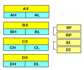
4 Data Registers
2 Pointer Registers
2 Index Registers
Data Register — Accumulator (AX):
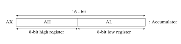
used in input/output and most arithmetic instructions.
Note:
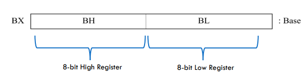
16 bits : AX BX CX DX
8 bits : AH AL BH BL CH CL DH DL
The "H" and "L" suffix on the 8-bit registers stand for high byte and low byte
Data Register — Data (DX):
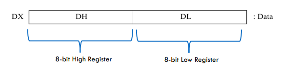
Used in input/output operations.
holds the port number for the IN and OUT instructions
Can be used with AX for multiply and divide operations involving large values.
Data Register — Counter (CX):
The counter register is used as a control register, mainly to store counter for loops.
E.g.: store counter i of a loop
Data Register — Base (BX):
The base register is used to store the offset values for indexing addressing.
The offset value is used to map the virtual address to the physical address.
Registers — Pointer Registers:
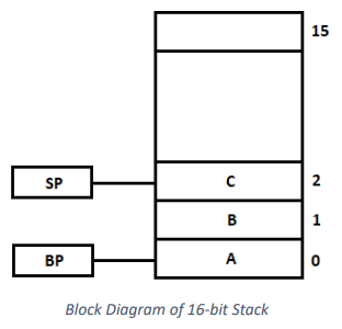
Pointer registers are used in conjunction with the stack.
The stack is an area of memory for keeping temporary data.
Registers — Memory Stack:
Memory stacks are data-structures vital for managing program execution:
Function Call Management: Tracks and manages the order of function calls during program execution.
Local Variable Storage: Stores local variables within each function's scope.
Control Flow Management: Ensures the orderly execution and return of function calls in a Last-In-First-Out (LIFO) manner.
Registers — Pointer Registers:
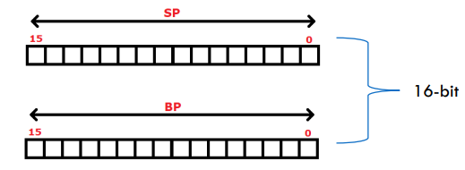
Stack Pointer (SP): The stack pointer is a memory pointer that points to the topmost element of the stack.
Base Pointer (BP): The base pointer is a memory pointer that stores the base address of the stack. This pointer allows code to independently reference data that have been pushed previously on the stack.
Registers — Index Registers:
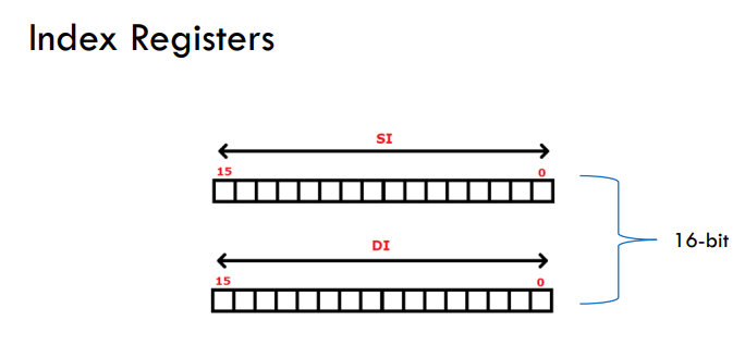
An index register is a processor register used for pointing to operand addresses during the run of a program.
Source Index (SI): used in the pointer addressing of data and as a source in some string-related operations.
Destination Index (DI): used in the pointer addressing of data and as a destination in some string-related operations.
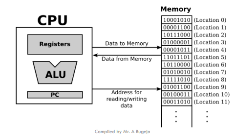
Addressing Modes — Memory Addressing:
Memory addressing in the 8086 processor is the process of specifying the location of data or instructions in memory.
Addressing Modes — Addressing Data in Memory:
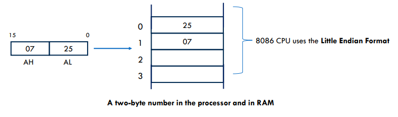
A processor may access one or more bytes of memory at a time.
Consider a hexadecimal number 0725H. (Requires 16-bits (2 bytes) of memory.)
The high-order (most significant) byte is 07
The low-order (least significant) byte is 25
Processor stores data in reverse-byte sequence
The low-order byte is stored in low memory address
The high-order byte in high memory address.
So, if processor brings the value 0725H from register to memory, it will transfer 25 first to the lower memory address and 07 to the next memory address.
Addressing Mode — Addressing Main Memory:
In assembly language programming, there are TWO different ways of specifying memory locations or addresses within a computer's memory.
Absolute Address
Relative Address

Addressing Modes — Absolute Address:
Absolute addressing is when you specify the actual memory location to which you are referring to.
It is typically a numeric value that directly points to a specific memory location.
These addresses do not change during program execution and are often used for variables, constants, and specific data structures.
E.g. MOV AX,0810H; loads into AX from the absolute memory location 0810H
Addressing Modes — Relative Address:
In relative addressing also known as symbolic addressing, the programmer can refer to a label or a reference point as the memory address.
A relative address specifies an offset or displacement from the reference point rather than an absolute location.
The assembler is left to map to which memory location the offset or label is pointing.
E.g. 1: MOV AL, DATA ; loads AL from the symbolic memory location DATA
E.g. 2: MOV AL, [SI+2] ; loads AL from the symbolic memory location Source Index + Offset 2
Advantages of Relative (Symbolic) Addressing:
The program is re-locatable in memory and may be loaded on different machines with the same architecture without any issues.
Addressing Modes:
Refer to the different ways in which the source and/or destination for the data may be represented.
Register Addressing
Immediate Addressing
Direct Addressing
Indirect Addressing
Indexed Addressing
Addressing Modes — Register Addressing:
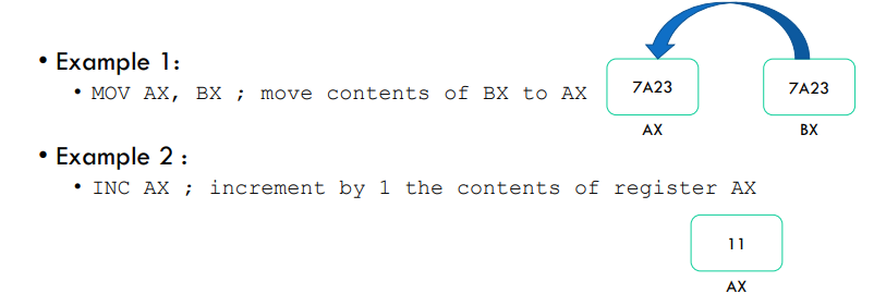
Register addressing happens when the register is the operand/s for an instruction.
Addressing Modes — Immediate Addressing:
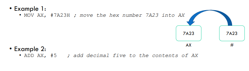
In immediate addressing the value/data of the operand is specified in the instruction itself.
The symbol # hash is used to specify an immediate value/data.
Addressing Modes — Direct Addressing:
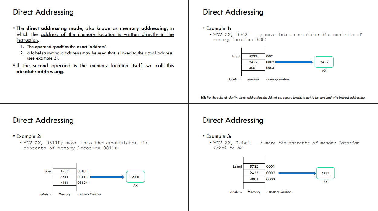
The direct addressing mode, also known as memory addressing, in which the address of the memory location is written directly in the instruction.
The operand specifies the exact ‘address’.
a label (a symbolic address) may be used that is linked to the actual address (see example 3).
If the second operand is the memory location itself, we call this absolute addressing.
Addressing Modes — Indirect Addressing:
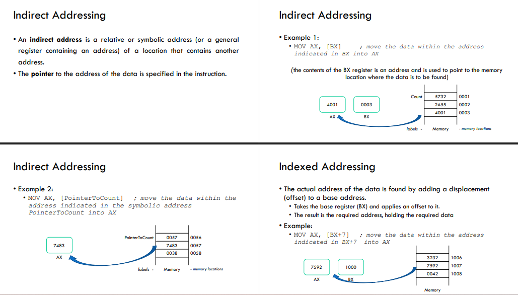
An indirect address is a relative or symbolic address (or a general register containing an address) of a location that contains another address.
The pointer to the address of the data is specified in the instruction.
Instruction Groups:
The instruction groups (categories) for the 8086 processor include:
Data Transfer Instructions
Stack Instructions
Logical Instructions
Arithmetic Instruction
Flag Manipulation Instructions
Shift and Rotate Instructions
Instruction Groups — Data Transfer:
Data transfer instructions are the operations that transfer data in the microprocessor:
from register to register
to the processor
to the main memory (RAM).
They are also called copy instructions
Instruction Groups; Data Transfer — MOV Instruction:
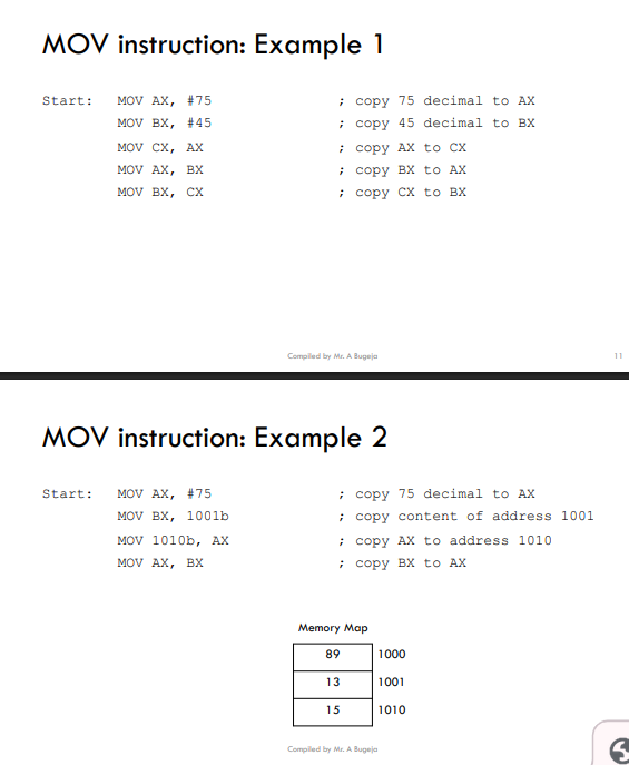
The MOV (move) instruction copies the data item referred to by its second operand (i.e., register contents, memory contents, or a constant value) into the location referred to by its first operand (i.e. a register or a memory location).
i.e. it is used to transfer data from:
CPU to memory and vice-versa
CPU register to another register
In the MOV instruction:
Both operands must be the same size (i.e., both 8 bits or 16 bits)
Source operand
Destination operand
Examples:
Example 1: MOV AX, BX ; move the content of BX into AX register
Example 2: MOV BX, 8110H ; move the data at memory location 8110 hex into BX
Example 3: MOV BX, 1100 ; move the data at memory location binary 11002 into BX MOV Instruction
Example 4: MOV BX, #1000; move the immediate binary value 10002 into BX
Example 5: MOV CX, ‘A’; move ASCII character ‘A’ into CX register
Example 6: MOV AX, Count ; move the contents of memory address count in register AX :Both operands cannot be memory locations. (You need an intermediary register to do so)
Examples of illegal MOV instructions:
Example 1: MOV 1000b, 1001b; illegal move from one memory location to another. You need an intermediary register
Example 2: MOV AL, #A12FH; illegal move as value A12F hex cannot be stored in register AL which is 8 bits.
Instruction Groups; Data Transfer — Tracing Table:
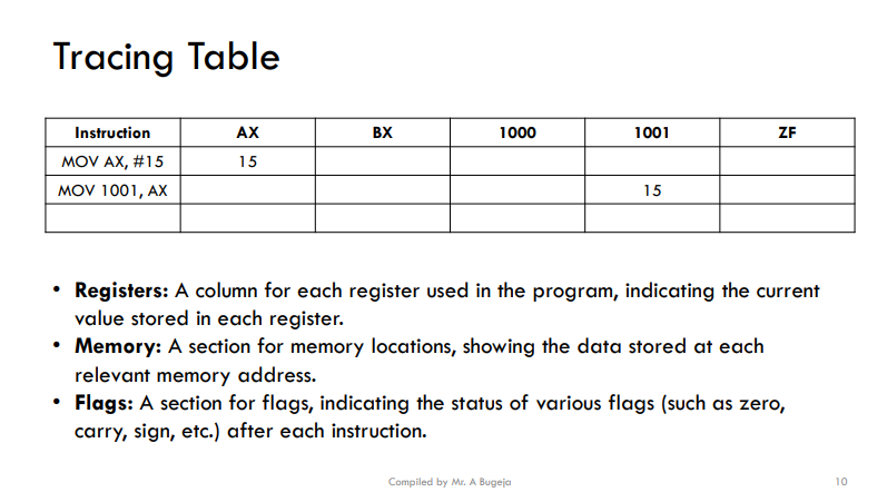
A tracing table refers to a method for manually tracking the state of registers, memory, and other relevant information during the execution of a program.
It helps programmers understand the flow of data and the state of the system at various points in the program's execution (debugging).
Instruction Groups; Data Transfer — MOV Instruction:
Instruction Groups — Arithmetic Instructions:
The Intel 8086 processor supports a variety of arithmetic instructions in its assembly language.
Here are some common arithmetic instructions:
ADD
ADC Add with carry
SUB
SBB Subtract with borrow
INC Increment
DEC Decrement
NEG Negation
CMP Compare
Instruction Groups; Arithmetic Instructions — ADD: Addition Instruction:
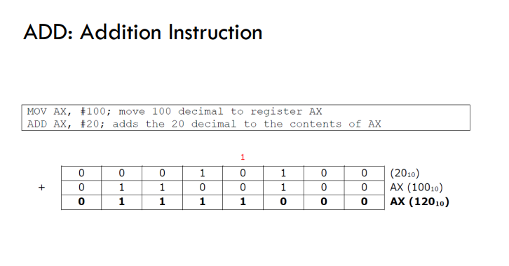
In the 8086-assembly language, the ADD is used for addition operations.
ADD destination, source; adds the source operand to the destination operand and stores the result in the destination operand.
DEST := DEST + SRC;
Example of ADD: Addition Instruction:
Example 1:Add 3 to the contents of register
AX ADD AX, #3
Example 2: Add 3 and 5
MOV AX, #3
ADD AX, #5
Example 3: Add 30 and 45 and save the result in memory location total
MOV AX, #30
ADD AX, #45
MOV total, AX
Example 4: Add contents of BX to the contents of AX
MOV AX, #7
MOV BX, #7
ADD AX, BX
Example 5: Add 10001000 to 00010001
MOV AX, #10001000b
MOV BX, #00010001b
ADD AX, BX
Instruction Groups; Arithmetic Instructions — SUB: Subtraction Instruction:
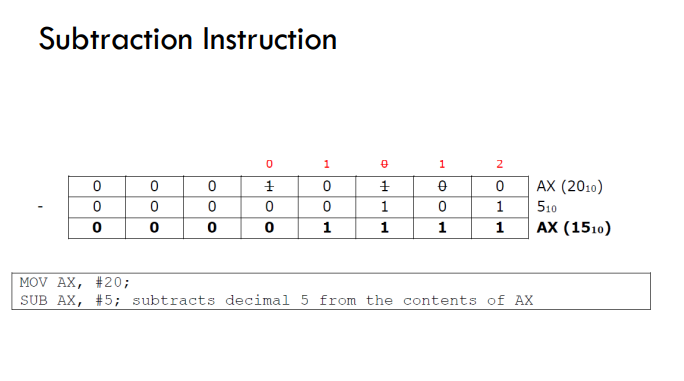
In the 8086-assembly language, the SUB is used for subtraction operations.
SUB destination, source ; subtracts the source operand from the destination operand and stores the result in the destination operand.
DEST := DEST – SRC;
Example 1: Subtract 3 from the contents of register
AX SUB AX, #3
Example 2: Subtract 3 from 5
MOV AX, #5
SUB AX, #3
Example 3: Subtract 30 from 45 and save the result in memory location difference
MOV AX, #45
SUB AX, #30
MOV difference, AX
Example 4: Subtract contents of BX from the contents of AX
MOV AX, #7
MOV BX, #7
SUB AX, BX
Example 5: Subtract BX from AX
MOV AX, #10001000b
MOV BX, #00010001b
SUB AX, BX
Instruction Groups; Arithmetic Instructions — Addition & Subtraction Instruction Limitations:
The ADD & SUB instruction cannot directly add/subtract two values from main memory locations.
The ADD instruction requires at least one of its operands to be a register or an immediate value, but not both operands can be memory locations.
Example 1 (not allowed):
ADD 1000, 1001
Example 2 (allowed):
MOV AX, 1001
ADD AX, 1000
Instruction Groups; Arithmetic Instructions — ADC: Addition with Carry:
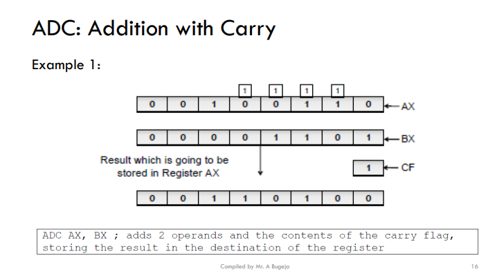
ADC is the same as ADD but it adds the destination operand, the source operand, and the carry (CF) flag and stores the result in the destination operand.
ADC destination, source
dest = dest + src + CF
Instruction Group; Arithmetic Instructions — Carry Flag:
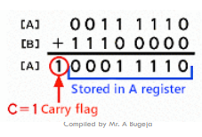
The carry flag (CF) indicates if an arithmetic operation caused a carryout or borrow.
Set when an addition generates a carry, or a subtraction requires borrowing.
The carry flag is a single-bit value that can be either 0 or 1.
Example 2: Given that CF=1
MOV AL, #01
MOV BL, #02
ADC AL, BL
ANS: AL = 1(AL)+ 2(BL) + 1(CF) = 4
Instruction Groups; Arithmetic Instructions — SBB: Subtraction with Borrow:
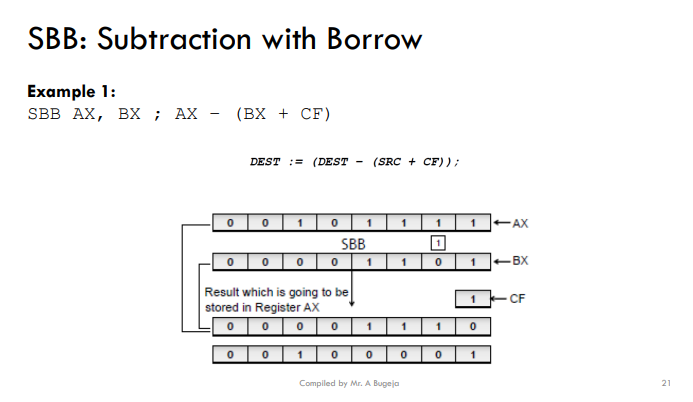
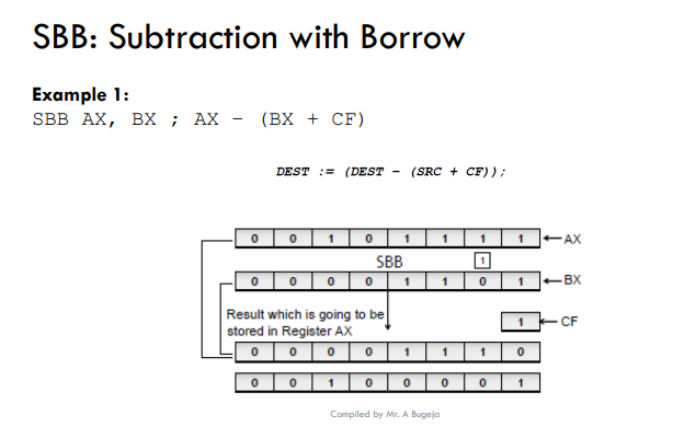
Subtracts ‘source’ + ‘carry flag’ from ‘destination’, storing result in destination.
SBB destination, source
dest = dest – (src + CF)
Example 2:
MOV AX, #4 ; AX = 4
MOV BX, #3 ; BX = 3
SBB AX, BX ; SUB with carry borrow flag set to 1
Example 3:
MOV AX, #5 ; AX = 5
MOV BX, #2 ; BX = 2
SBB AX, BX ; SUB with carry borrow flag set to 0
Instruction Groups; Arithmetic Instructions — Borrow Flag V.S. Carry Flag:
The terms "carry flag" and "borrow flag" often refer to the same flag, which is the Carry Flag (CF).
The terms "carry" and "borrow" refer to the direction of the operation.
If you're adding, you're concerned with carrying bits beyond the most significant bit (carry).
If you're subtracting, you're concerned with borrowing from the most significant bit (borrow).
Example 2:
MOV AX, #4 ; AX = 4
MOV BX, #3 ; BX = 3
SBB AX, BX ; SUB with carry borrow flag set to 1
Example 3:
MOV AX, #5 ; AX = 5
MOV BX, #2 ; BX = 2
SBB AX, BX ; SUB with carry borrow flag set to 0
Instruction Groups; Arithmetic Instructions — Increment & Decrement:
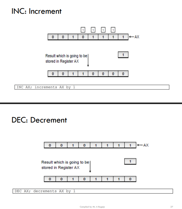
INC, DEC instructions
INC: increments the contents of the register by 1.
DEC: decrements the contents of the register by 1.
Example 1: Add 5 to 6 and then increment the result by 1
MOV AX, #5
ADD AX, #6
INC AX
Instruction Groups; Arithmetic Instructions — MUL: Multiplication:
In 8086 assembly language, the MUL (multiplication) instruction is used to perform unsigned multiplication.
MUL is used to multiply the content of the specified register or memory operand by the value in the accumulator (AX register).
Result is stored in register AX.
MUL BX ; Multiply BX by AX and store the result in AX
Note regarding MUL instruction: AX is part of the MUL instruction even though it is not mentioned.
Example 1: Work the following : (5 - 2) x 4 and put answer in AX
MOV AX, #5 ; put 5 into register AX
MOV BX, #4 ; put 4 into register BX
SUB AX, #2 ; subtract 2 from AX
MUL BX ; multiply the number in BX register by the AX register and leave answer in AX
Instruction Groups; Arithmetic Instructions — DIV: Division:
In 8086 assembly language, the DIV (divide) instruction is used to perform unsigned division.
DIV is used to divide the value in the accumulator register AX by the specified register or memory operand.
1. The quotient is stored in the accumulator (AX register).
2. The remainder is stored in the data register (DX register)
DIV BX ; divide AX by BX, quotient in AX, remainder in DX
Note regarding DIV instruction: the quotient is stored in AX while the remainder in DX
Example 1:
MOV AX, #40
MOV BX, #4
DIV BX ; AX = 10 , DX = 0
Example 2:
MOV AX, #5
MOV BX, #2
DIV BX ; AX = 2 , DX = 1
Instruction Groups; Arithmetic Instructions — NEG: Negation:
The NEG instruction negates a value by finding 2's complement of its single operand.
This simply means multiply operand by -1.
1. When a positive value is negated the result is negative.
2. A negative value will become positive.
3. Zero remains zero.
Example 1:
MOV AL, -1 ; Load register
NEG AL ; AL now has 1
Example 2:
MOV AL, +5 ; Load register
NEG AL ; AL now has -5
Example 3:
MOV AL, 0 ; Load register
NEG AL ; AL remains 0
Instruction Groups; Arithmetic Instructions — CMP: Compare:
The CMP or Compare instruction will be covered at a later stage once we introduce branching/jumping in Assembly.
Instruction Groups — Logical Instructions:
Logical instructions in assembly language are commands that perform basic logical operations on binary data.
Logical instructions are essential in computer programming and digital systems because they allow for:
decision-making
control flow based on specific conditions.
The Intel 8086 processor supports a variety of logical instructions in its assembly language.
Here are some common logical operations:
AND
OR
NOT
XOR
TEST (Logical Compare)
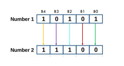
These instructions operate in bitwise mode.
Each bit is matched against the equivalent bit in another register
Instruction Groups; Logical Instructions — AND: Logical AND:
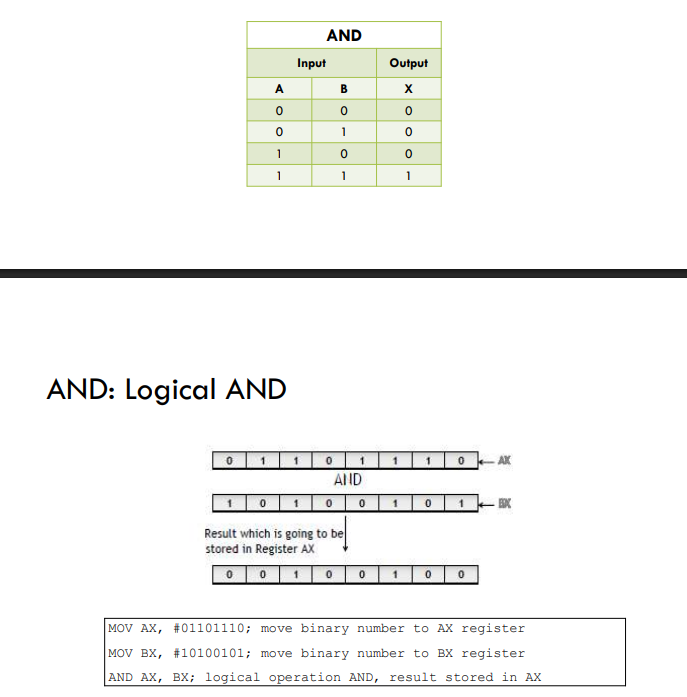
Performs bitwise AND operation between the destination and source operands.
AND destination, source
Example 1:
MOV AL, #0001 1111
MOV BL, #0001 1011
AND AL, BL
Example 2:
MOV AL, #22
MOV BL, #50
AND AL, BL
Instruction Groups; Logical Instructions — OR: Logical OR:
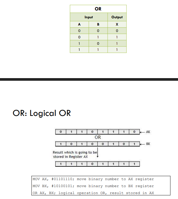
Performs bitwise OR operation between the destination and source operands.
OR destination, source
Example 1:
MOV AL, #0001 1111
MOV BL, #0001 1011
OR AL, BL
Example 2:
MOV AL, #54
MOV BL, #88
OR AL, BL
Instruction Groups; Logical Instructions — NOT: Logical NOT:
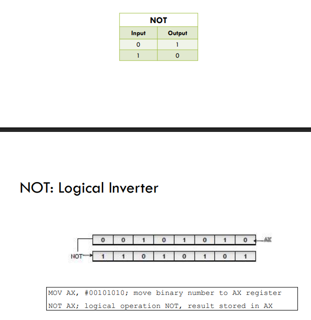
Performs bitwise NOT operation on the operand, inverting each bit.
NOT operand
Example 1:
MOV AL, #0011 1011
NOT AL
Example 2:
MOV AL, #37
NOT AL
Instruction Groups; Logical Instructions — XOR: Logical Exclusive OR:
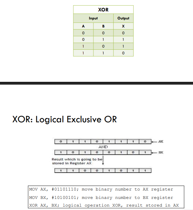
Performs bitwise exclusive OR (XOR) operation between the destination and source operands.
XOR destination, source
Example 1:
MOV AL, #0101 1101
MOV BL, #0001 1011
XOR AL, BL
Example 2:
MOV AL, #42
MOV BL, #51
XOR AL, BL
Instruction Groups; Logical Instructions — TEST (Not in Syllabus):
The TEST instruction performs a bitwise AND operation as well but does not store the result.
It is used primarily for setting flags based on the result.
Instruction Groups — Shift and Rotate Instructions:
In assembly language programming shift instructions are used to shift the bits of a binary value to the left or right.
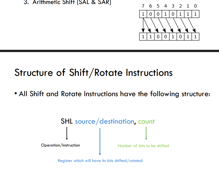
There are THREE different types of Shift Instructions:
Logical Shifts (SHL & SHR)
Rotate Instructions (ROL, ROR, RCL & RCR)
Arithmetic Shift (SAL & SAR)
All Shift and Rotate Instructions have the following structure:
SHL source/destination, count
SHL - Operation/Instruction
Source/Destination - Register which will have its bits shifted/rotated
Count - Number of bits to be shifted
Instruction Groups; Shift and Rotate Instruction — Logical Shifts (SHL, SHR):
A logical shift instruction shifts (moves) each binary digit left or right and fills up vacating spaces with zero (0) or zeros (0s).
The carry flag (CF) receives the value of the least significant bit (LSB) or most significant bit (MSB) that is shifted out.
The carry flag (CF) or (CY) indicates if an arithmetic operation caused a carry-out or borrow.
Set when an addition generates a carry, or a subtraction requires borrowing. • The carry flag is a single-bit value that can be either 0 or 1.
Instruction Groups; Shift and Rotate Instruction — Examples of Logical Shifts (SHL, SHR):
Instruction Groups; Shift and Rotate Instruction — Rotate Instructions (ROL & ROR):
When using shift instructions, we risk bits ‘falling off the end’, thus being lost forever.
Rotate instructions ROL (Rotate Left) and ROR (Rotate Right) are used on occasions when we do not wish to throw this information away.
Instruction Groups; Shift and Rotate Instruction — Rotate Left (ROL) Instruction:
The ROL instruction shifts the bits in the destination operand to the left by the specified count.
The carry flag (CF) receives the value of the MSB (most significant bit) before the rotation.
The MSB itself is shifted into the LSB (least significant bit).
Instruction Groups; Shift and Rotate Instruction — Rotate Right (ROR) Instruction:
The ROR instruction shifts the bits in the destination operand to the right by the specified count.
The carry flag (CF) receives the value of the LSB (least significant bit) before the rotation.
The LSB itself is shifted into the MSB (most significant bit).