Fundaments of Fluoroscopic Imaging
1/23
There's no tags or description
Looks like no tags are added yet.
Name | Mastery | Learn | Test | Matching | Spaced |
|---|
No study sessions yet.
24 Terms
Fluoroscopy
The production of dynamic (moving) radiographic images in real time (as they occur)
Invented by Thomas Edison in 1896
one year after Roentgen discovered x-ray
The original Fluoroscope
Consisted of a metal cone with a fluorescent screen in the bottom and a viewing window in the top
Open Fluoroscopy
a large intensifying screen was positioned behind patient in a completely darkened room - the radiologist had to dark-adapt his eyes to the very dim image
*exposure to both the patient and the radiologist (whose head was directly in the remnant x-ray beam) was high.
Where should x-ray tube be…
underneath patient is best
Where should image intensifier be…
Above patient, as close as possible
Mobile Image Intensification (C-Arm)
Less scatter radiation is delivered to personnel by placing the image intensifier above the patient, with the x-ray tube under the table.
Carbon Fiber tables allow significant reductions in patient exposure
Note
tube be 12 inches away from the patient… NEED to bring i.i. down during procedures.
Bringing the i.i. closer also improves spatial resolution (reduces magnification)
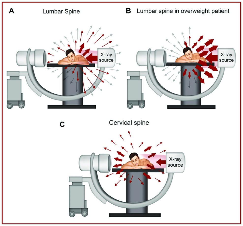
Reminder …
The patient is our source of dose - where is their scatter direction
RF System…
capable of both radiography and fluoro imaging
Fluoro detector may be under the patient (so tube on top)
Very common fluoro room of today
can do static and dynamic imaging
Development of Improving Dose
Image intensifier Tube:
invented by John Coltman in 1948
Converted the x-ray image into an electron bean that could be accelerated and focused for intensification
Dramatically reduced the mA required, saving patient dose
The image Intensifier tube
Purpose - convert the remnant radiation beam into an amplified light image
change one form of energy into another
A large evacuated glass envelope, or vacuum tube, containing 5 electronic components
the vacuum adds its efficiency
Available in diameters of 15, 23, 30, or 40 cm (6, 9, 12 or 16 inches) at the input phosphor
The output phosphor is always 2.5 cm in diameter (always 1 inch)
Concentration of the beam from the input to the output phosphor increases brightness by thousands of times
Increasing the physical diameter of the input phosphor results in increased image resolution, since a larger number of pixels are focused onto the same output size, forcing the output pixel size to be reduced.
Mag mode increases spatial resolution too = reduced FOV
The Input Phosphor
Primary Barrier
A layer of fluorescent crystals of cesium iodide (beneficial)
Absorbs x-rays and re-emit energy as yellow-green light
changes x-ray photons to light photons
Needle shaped crystals helps prevent lateral dispersion of light
The Photocathode
A thin photoemissive metal layer, made of a combination of antimony and cesium compounds
Upon absorbing light energy, emits electrons
utilizes the photoelectric effect to do so
Thus, a beam of millions of electrons is produced
(x-rays go into photocathode, electrons come out of photocathodes)
The Electrostatic Focusing Lens
A series of positively - charged metal rings that become narrower toward the anode end of the tube.
Stronger positive charge on each narrower ring focuses the electron beam onto the output phosphor.
Concentrating the electrons increases output intensity
This process is call minification
Minification Gain =
Input phosphor diameter ² / Output phosphor diameter ²
The Accelerating Anode
A small ring of metal in the “Neck” of the tube with 25,000-30,000 volts of positive charge applied to it.
Resulting acceleration of electrons imparts 50-75 times the kinetic energy they start with
This gain in “flow” or flux gain also increases output intensity
Flux - Flow of light
The number of light photons emitted by the output phosphor to the number of x-rays that struck the input phosphor
Flux Gain =
# of output light photons / # of input x-ray photons
The Output Phosphor
ALWAYS 2.5 cm; about 1 inch in diameter
Made of cesium iodide or zinc cadmium sulfide
Converts the kinetic energy of the electrons striking it into light
This light image is then picked up by a CCD or CMOS camera