L03 - Start-up of Liquid rocket engines
1/39
There's no tags or description
Looks like no tags are added yet.
Name | Mastery | Learn | Test | Matching | Spaced |
|---|
No study sessions yet.
40 Terms
Why is the start-up of liquid rocket engines important?
Ensuring the engine reaches its steady-state operating point without exceeding component limits.
Failures during start-up can lead to mission loss.
Understanding the start-up sequence helps in designing reliable engines and avoiding issues like ignition overpressure, water hammer, and combustion instabilities.
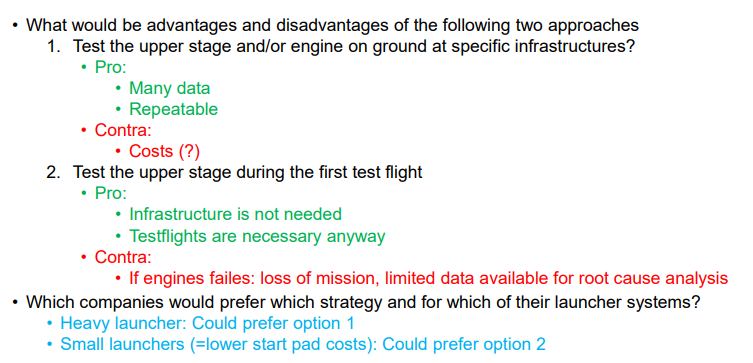
• What would be advantages and disadvantages of the following two approaches
1. Test the upper stage and/or engine on ground at specific infrastructures?
2. Test the upper stage during the first test flight
• Which companies would prefer which strategy and for which of their launcher systems?
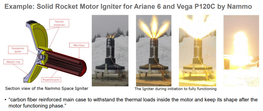
Startup of Solid Rocket Motors
How?
Advantages and disadvantages
Example
Solid rocket motors are simpler to start compared to liquid engines because they involve no fluids.
Initiation is typically done through a small energy input (e.g., wire shorting or igniting black powder).
Advantages: Simple and reliable.
Disadvantages: Cannot be shut down or restarted once ignited.
Example: NASA's Space Launch System (SLS) and Space Shuttle used solid rocket boosters.
Short Recapitulation on Engine Cycles
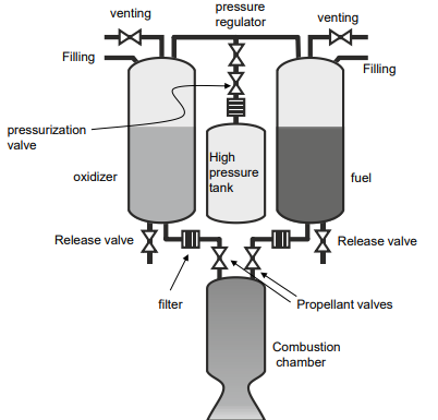
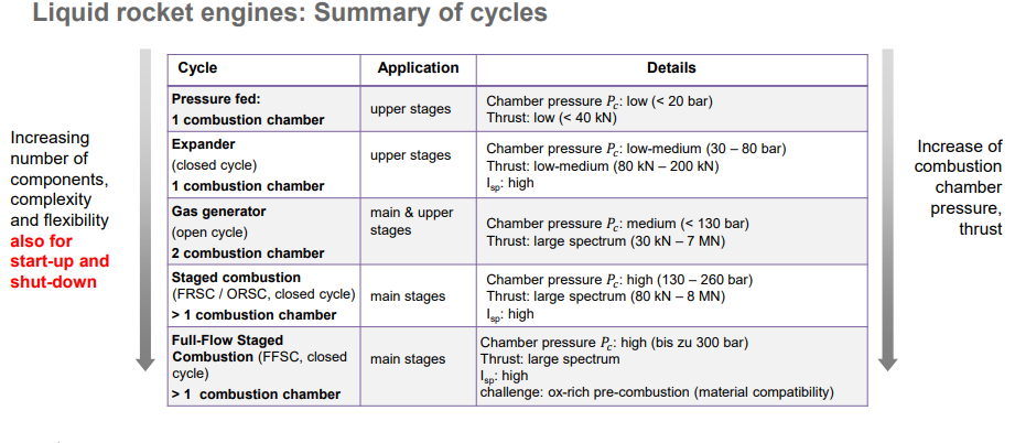
Pressure-Fed Engines:
How it works, Applications, Advantages, Disadvantages, Start-up sequence
Pressure-Fed Engines:
How it works: Propellants are fed into the combustion chamber using high-pressure tanks.
Applications: Upper stages, reaction control systems.
Advantages: Simple and reliable.
Disadvantages: Limited thrust and chamber pressure.
Start-up sequence: Fill propellant lines, open valves, and ignite.
Short Recapitulation on Engine Cycles
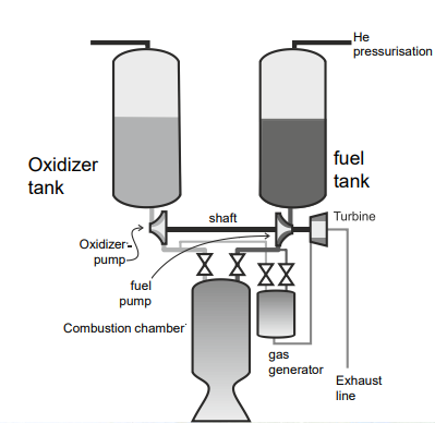
Pump-Fed Engines:
How it works, Applications, Advantages, Disadvantages, Start-up sequence
Pump-Fed Engines:
How it works: Propellants are fed by pumps driven by turbines.
Applications: High-thrust engines, booster and main stage engines.
Advantages: Higher thrust and efficiency.
Disadvantages: More complex start-up sequence.
Start-up sequence: Chill-down, priming, ignition of gas generator or pre-burner, and main combustion chamber.
Short Recapitulation on Engine Cycles
Engine Cycles Summary:
TABLE: Cycle, Application, Details
Short recapitulation on engine cycles & ignition
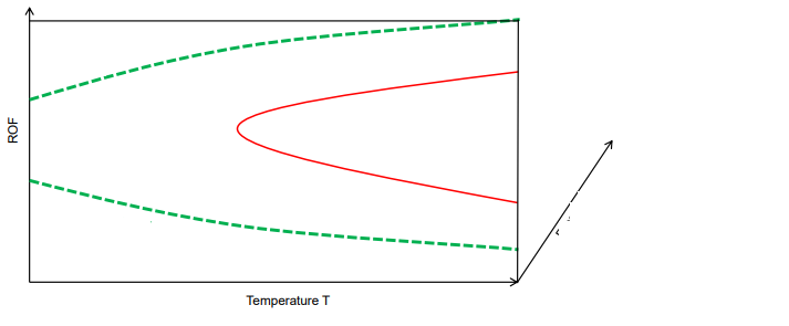
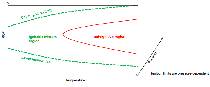
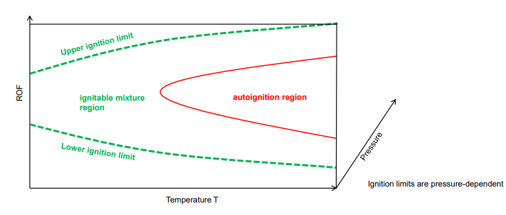
Ignition limits in the (ROF, T) diagram
A (ROF, T) diagram presents ignition limits based on mixture ratio (ROF) and temperature.
The "ignitable mixture region" is between upper and lower ignition limits.
An "autoignition region" indicates conditions where ignition occurs spontaneously.
Ignition limits are pressure-dependent.
Short recapitulation on engine cycles & ignition
ROF (Ratio of Oxidizer to Fuel)
ROF (Ratio of Oxidizer to Fuel) is the mass or molar ratio of oxidizer to fuel in a combustion process. It influences flame stability, ignition characteristics, and overall engine performance. Different ROF values affect combustion efficiency and pressure dynamics.
Short recapitulation on engine cycles & ignition
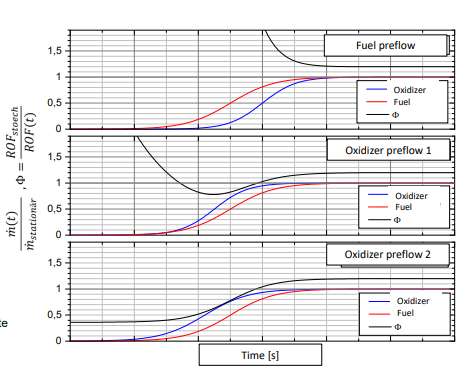
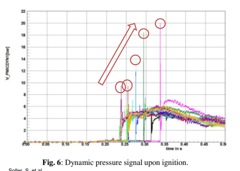
Ignition sequences
Startup sequence has great influence on
Graphs show different preflow conditions?
ROF(t)
Ignition and flame propagation
Pressure peak
Flame stabilization
Combustion stability
Graphs show different preflow conditions:
Fuel excess
Temporary oxidizer excess
Steady-state oxidizer excess
Short recapitulation on engine cycles & ignition
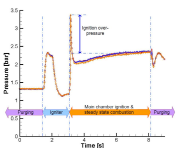
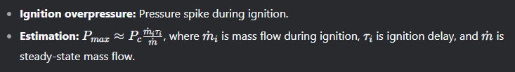
Ignition overpressure
Key factors
How can be avoided
Ignition delay affects overpressure.
Pressure can exceed steady-state levels if ignition timing is not optimized.
A formula estimates maximum ignition pressure based on combustion parameters.
Ignition overpressures must be avoided by accumulation of propellants
General comments on start-up and shut down of engines
Complexity
Close-loop vs open-loop control comperision wrt complexity
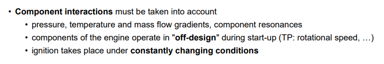
Component interaction
Complexity increases with the number of propellants and components.
Closed-loop control (valves depend on real-time measurements) is more complex than open-loop control (fixed sequence).
Components operate in off-design conditions during start-up, requiring careful management of pressure, temperature, and mass flow.
General comments on start-up and shut down of engines
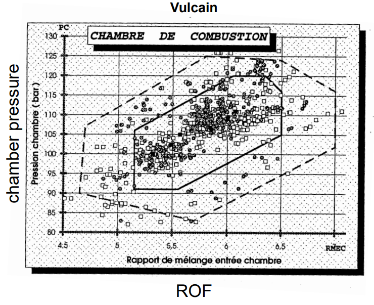
Operating Points and Engine Envelope
Engines have design and off-design operating points.
The operational envelope is limited by individual component limits.
Components with larger operational ranges are more complicated, heavier and have increased risks of failure.
Trade-off necessary for both engine and individual components
Throttable engines require verification of multiple target operating points.
General comments on start-up and shut down of engines
Global Goals for Start-Up
Reach steady-state operation without exceeding component limits (e.g., turbopump speed, thermal limits).
Avoid issues like ignition failure, pressure peaks (water hammer, ignition overpressure), and instabilities (e.g., pogo effects).
General comments on start-up and shut down of engines
Transient phases
Fast start-up concept? Pros and Cons
Start-up: Includes preconditioning (chill-down), priming, power increase, ignition, and reaching the target load point.
Shut-down: Involves power drop, end of combustion, and conditioning.
Fast start-up reduces off-design operation but requires precise timing and control.
General comments on start-up and shut down of engines
Component Dependency: Open vs. Closed Cycles
Turbopump efficiency: Open vs. Closed Cycles
Open Cycle (e.g., Gas Generator): Less dependency between components, less sensitive to turbopump efficiency.
Closed Cycle (e.g., Staged Combustion): Strong dependency between components, sensitive to turbopump efficiency, and combustion chamber ROF matches global ROF.
Effects and challenges of (cryogenic) two phase flows
Solution
Cryogenic propellants (e.g., LOX, LH2) can lead to two-phase flows, causing issues like cavitation, chugging, and thermoacoustic instabilities.
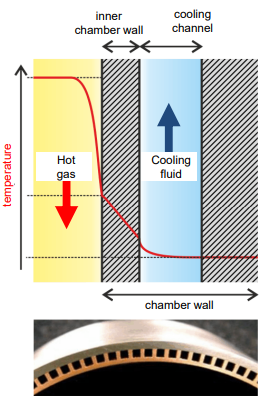
Combustion chamber(s) wall cooling: Nukiyama curve (see next slides)
Chill-down is essential to avoid two-phase flows by cooling tanks, pipes, turbopumps, and combustion chamber walls.
Important effects to consider: Two phase flows
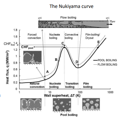
The Nukiyama curve
Describes heat transfer regimes in boiling liquids:
A-B: Forced convection (liquid below boiling point).
B-C: Nucleate boiling (bubbles form, increasing heat transfer).
C-D: Transition boiling (bubbles grow rapidly, heat transfer decreases).
D: Film boiling (Leidenfrost effect, gas film insulates, leading to burnout).
causing a decrease in heat flux • a rapid increase in wall temperature • -> often resulting in a burnout or melting of the wall material
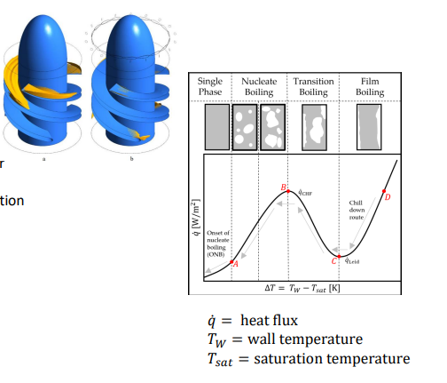
Cryogenic Chill-Down:
Why engines need that and what happens during chill-down
Prevents cavitation at pump inlets by maintaining low temperatures.
Ensures controlled fluid properties and mass flow during ignition.
Example: RL-10 engine uses chill-down to flow LOX through the system after liftoff.
Temperature controlled process • D → C → B → A
During chill down: • Decrease of 𝑇w
Ariane 5 Chill-Down:
Vulcain 2 (Main Stage): Chill-down with ground supply fluids, followed by tank chill-down.
HM7B (Upper Stage): Chill-down occurs in flight.
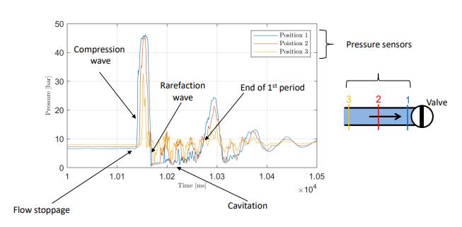
Water Hammer Effect:
Caused by sudden flow stoppage, leading to pressure waves that can damage the system.
Example: Closing the bypass valve during chill-down can create pressure peaks.
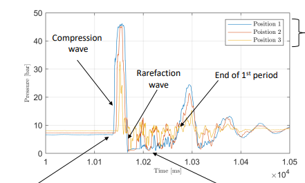
Fluid Hammer Experiments:
Tests on flow stoppage, pressure oscillations, and cavitation using LN2 (liquid nitrogen).
Pressure sensors measure compression and rarefaction waves during flow stoppage.
Ignition in Space: Challenges and Solutions
Challenges:
Absence of ground support equipment.
Propellant settling in tanks due to microgravity.
Solutions:
Use ullage thrusters or cold gas thrusters to settle propellants.
Hypergolic engines (self-igniting propellants) eliminate the need for ullage thrusters.
Concept: "Test as you fly – fly as you test" is challenging in low-gravity environments.
Example sequences of engine start ups
Start-Up Sequences:
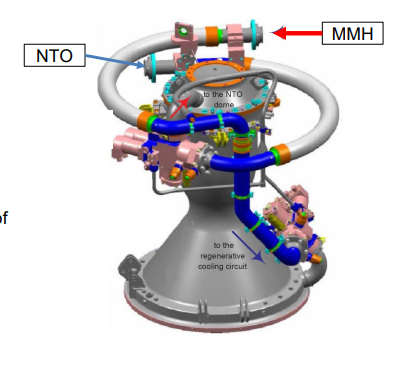
Pressure-Fed Cycle (Aestus)
Uses hypergolic propellants (MMH/NTO), so no igniter is needed.
Sequence: Fill fuel lines, open oxidizer valve, purge fuel lines, open fuel valve, hypergolic ignition.
Example sequences of engine start ups
Start-Up Sequences:
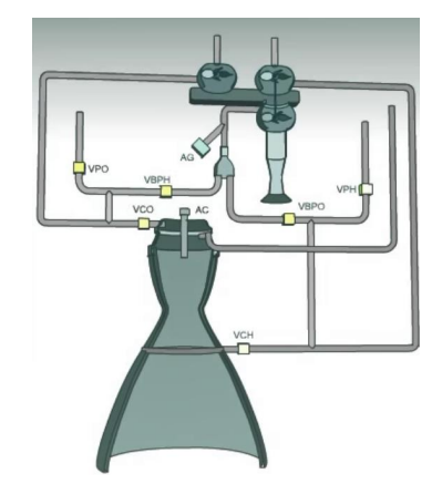
Gas Generator Cycle (Vulcain)
Chill-down of pumps (2.5 hours).
Open hydrogen valve (cool combustion chamber).
Open oxygen valve.
Ignite main combustion chamber (fuel-rich ignition).
Start gas generator (drives turbines).
Example sequences of engine start ups
Start-Up Sequences:
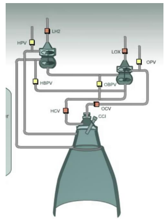
Expander Cycle (Vinci)
Chill-down of propellant lines, turbopumps, and combustor.
Activate main chamber igniter to heat the chamber.
Open fuel valve, fuel heats turbines.
Open oxygen valve, ignite main chamber.
Fuel heats further, increasing turbine power and chamber pressure.
Engine Models for Start & Cutoff Simulation
Purpose: To create digital twins of propulsion systems for optimizing:
Steady-state operation.
Start-up and cut-off sequences.
Generating data for machine learning approaches.
What effects have to be considered when starting-up of a liquid rocket engine?
Two-phase flows, chill-down, water hammer, ignition overpressure, combustion instabilities, and component interactions (pressure, temperature, mass flow gradients).
What has to be avoided when starting-up a liquid rocket engine?
Ignition overpressure, water hammer, combustion instabilities, exceeding component limits (e.g., turbopump speed, thermal limits), and failed ignition.
Can you describe the steps of the start-up of an expander cycle and gas-generator cycle?
Expander Cycle:
Chill-down of propellant lines, turbopumps, and combustor.
Activate main chamber igniter.
Open fuel valve, fuel heats turbines.
Open oxygen valve, ignite main chamber.
Fuel heats further, increasing turbine power and chamber pressure.
Gas Generator Cycle:
Chill-down of pumps.
Open hydrogen valve (cool combustion chamber).
Open oxygen valve.
Ignite main combustion chamber (fuel-rich ignition).
Start gas generator (drives turbines).
Why are electric pump-fed cycles easier to start-up compared to classic pump-fed cycles?
Electric pumps eliminate the need for gas generators or pre-burners, simplifying the start-up sequence.
Why do not all companies use electric pump-fed cycles?
Electric pumps may not provide the same thrust or efficiency as traditional turbopump systems, especially for large engines.
What would be advantages and disadvantages of the following development approaches?
1. Test on ground:
Advantages: More data, repeatable tests.
Disadvantages: High infrastructure costs.
2. Test during first flight:
Advantages: No need for ground infrastructure.
Disadvantages: Risk of mission failure, limited data for analysis.
Which companies would prefer which strategy and for which of their launcher systems?
Heavy launchers (e.g., SpaceX, ULA): Prefer ground testing due to higher costs of failure.
Small launchers (e.g., Rocket Lab): Prefer testing during first flight due to lower costs.
What are the challenges involved in igniting a liquid rocket engine?
Propellant settling in microgravity, precise timing of valve operations, avoiding ignition overpressure, and ensuring stable combustion.
Sketch the ignition limits in the (ROF, T) diagram and name the corresponding regions.
Regions: Ignitable mixture region, autoignition region, upper and lower ignition limits (pressure-dependent).
What is Fuel preflow and oxidizer preflow during a startup sequence?
Fuel preflow: Fuel flows into the combustion chamber before ignition.
Oxidizer preflow: Oxidizer flows into the combustion chamber before ignition.
What is ignition overpressure and how can it be estimated?
Name the goals of a startup sequence and effects to be avoided.
Goals: Reach steady-state operation without exceeding component limits.
Effects to avoid: Ignition overpressure, water hammer, combustion instabilities, and component damage.
What is the Nukiyama curve and why is the Leidenfrost effect so critical for rocket engines during start-up?
Nukiyama curve: Describes heat transfer regimes in boiling liquids.
Leidenfrost effect: Forms a gas film on hot surfaces, reducing heat transfer and risking burnout.
What is the purpose of engine models?
To simulate and optimize start-up, cut-off, and steady-state performance, and generate data for machine learning.