5.3 Circuits & The Potential Divider & 5.4 Electromotive Force & Internal Resistance
1/17
There's no tags or description
Looks like no tags are added yet.
Name | Mastery | Learn | Test | Matching | Spaced |
|---|
No study sessions yet.
18 Terms
How to find the resistance of two/more components connected in series?
To calculate the total resistance of resistors in series:
How to find the resistance of two/more components connected in parallel?
Calculate the total resistance of resistors in parallel:
What happens when more resistors added?
Example:
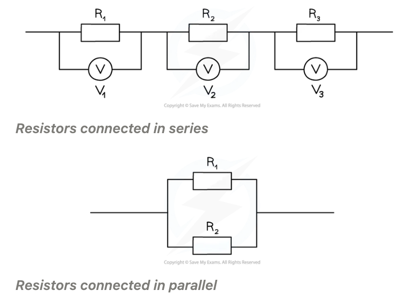
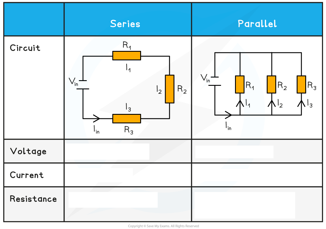
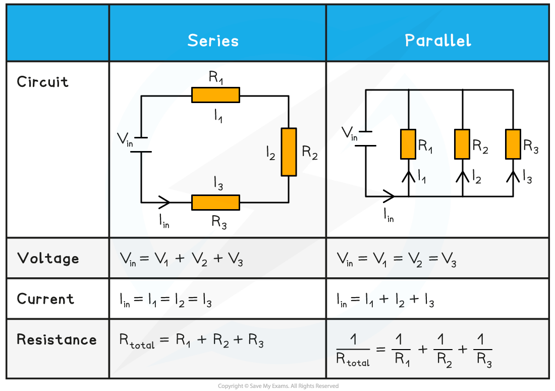
Two/more components connected in series: The combined resistance of the components is equal to the sum of individual resistances
Combined resistance in series = R = R1 + R2 + R3…
Two/more components connected in parallel: The reciprocal of the combined resistance is the sum of the reciprocals of the individual resistances
Combined resistance in parallel = 1/R = 1/R1 + 1/R2 + 1/R3…
More resistors added, combined resistance decreases so less than the resistance of the individual components
Example: two resistors of equal resistance connected in parallel, combined resistance will halve
What is the current in the series circuit?
What is the current in parallel circuit?
What does amount of current in each branch depend on?
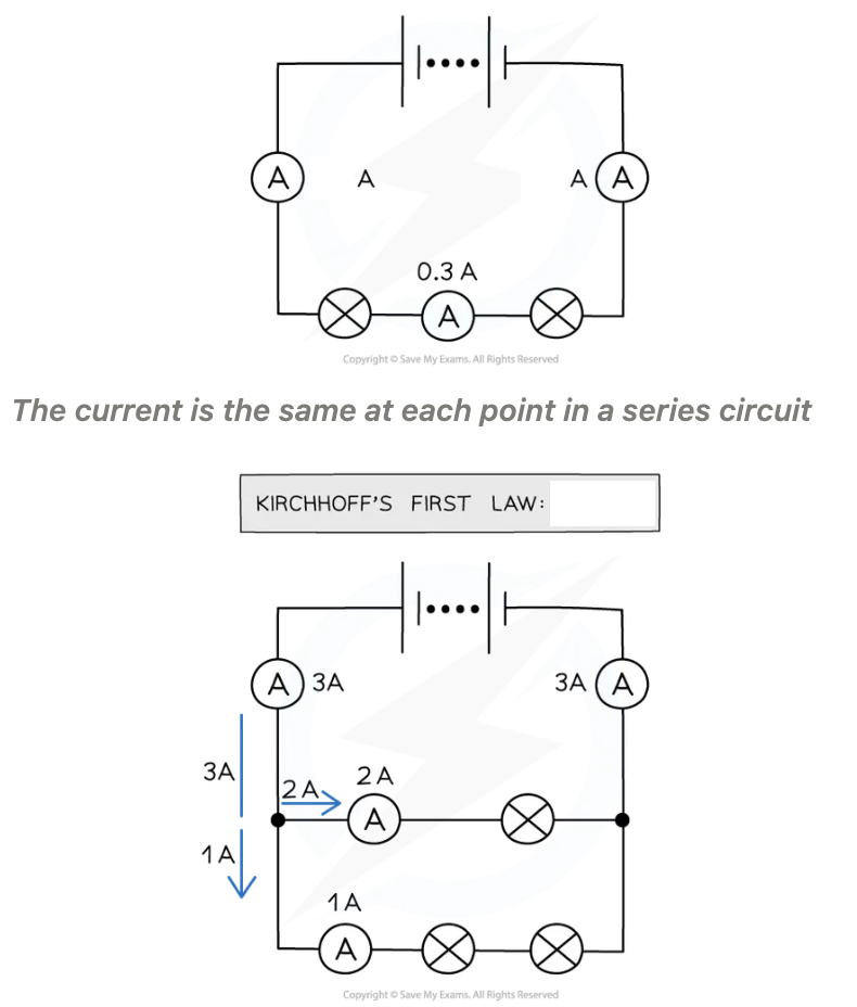
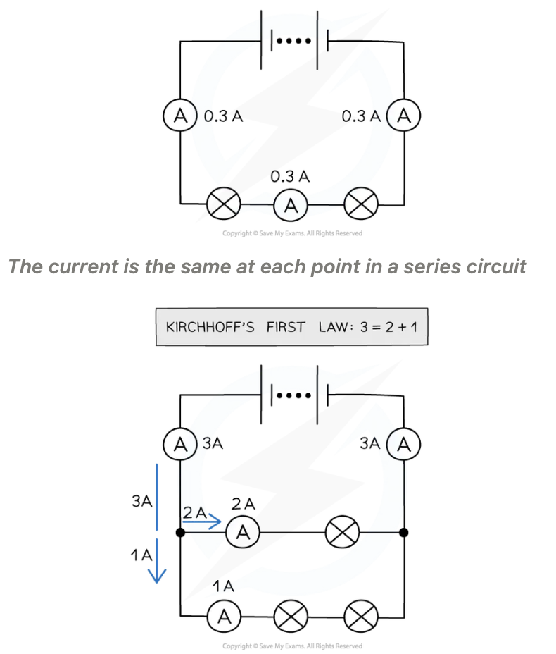
Series circuit, current is the same for all components
Parallel circuit, current split across different branches/ junction. Total current into junction must equal total current out of a junction
Amount current each branch depends on total resistance components within branch
Series circuit pd/emf:
Parallel circuit, voltage:
Cells connected in ____/_____
How is total voltage of combined cells calculated?ll
Series circuit, e.m.f of power supply shared amongst components different amounts, depending on resistance
Parallel circuit, voltage all components in each branch is equal to the e.m.f of the power supply
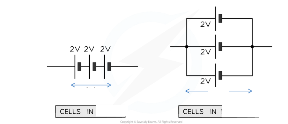
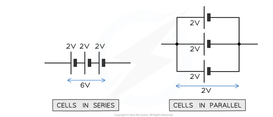
Cells connected in series/parallel
Total voltage of combined cells calculated in same way as voltage:
Cells connected in series, total voltage between ends of the chain of cells is sum of pd across each cell
Cells connected in parallel, total voltage across arrangement same as for one cell

conservation of charge:
Current in a parallel circuit:
What is a Junction and branch?
What happens when current is split into 2 branches?
Charge is ______ in both sides of the _______
Charge is never used up/lost in circuit - conservation of charge
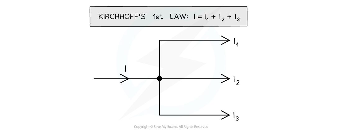
Current in a parallel circuit: The sum of the currents entering a junction always equal the sum of the currents out of the junction - Kirchhoff's First Law
In a circuit: junction is a point where at least three circuit paths meet, branch is a path connecting two junctions
Circuit splits into 2 branches the current before the circuit splits is equal to the current after it has split
Charge conserved on both sides of junction
What is current in a series circuit?
What is current in a parallel circuit?
In series circuit, current is the same through all components
Parallel circuit, current divides at junctions and each branch has a different value
conservation of energy:
Voltage in circuit:
Closed circuit can be treated like a _____ circuit
Energy never used up/lost in circuit - conservation of energy
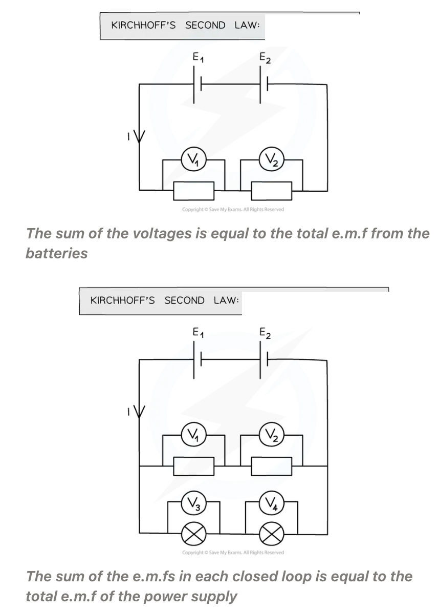
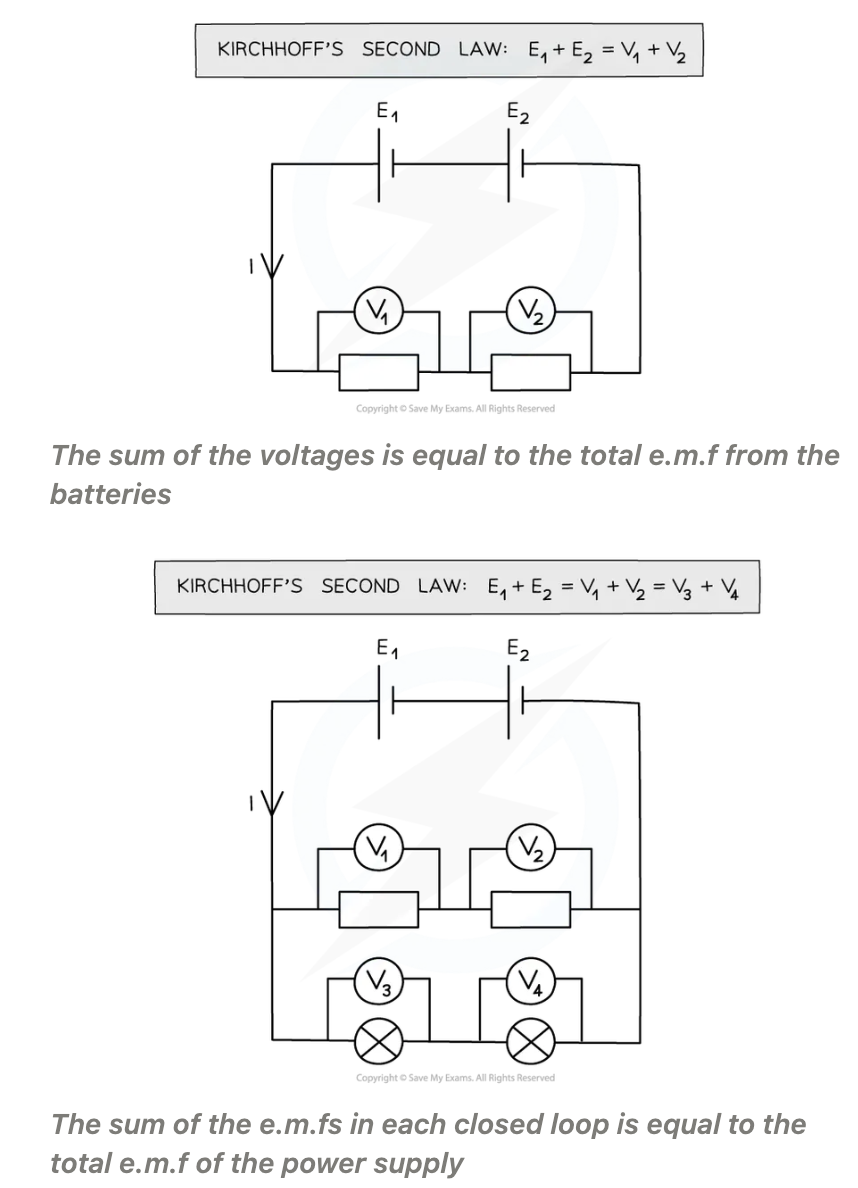
Voltage in circuit: The total e.m.f. in a closed circuit equals the sum of the potential differences across each component - Kirchhoff's Second Law
Closed circuit can be treated like a series circuit
Voltage in series circuit:
EMF of the power supply in series circuit is:
Voltage in parallel circuit:
EMF of the power supply in parallel circuit is:
Series circuit, voltage split across all components depending on their resistance
Sum of voltages equal to total e.m.f of the power supply
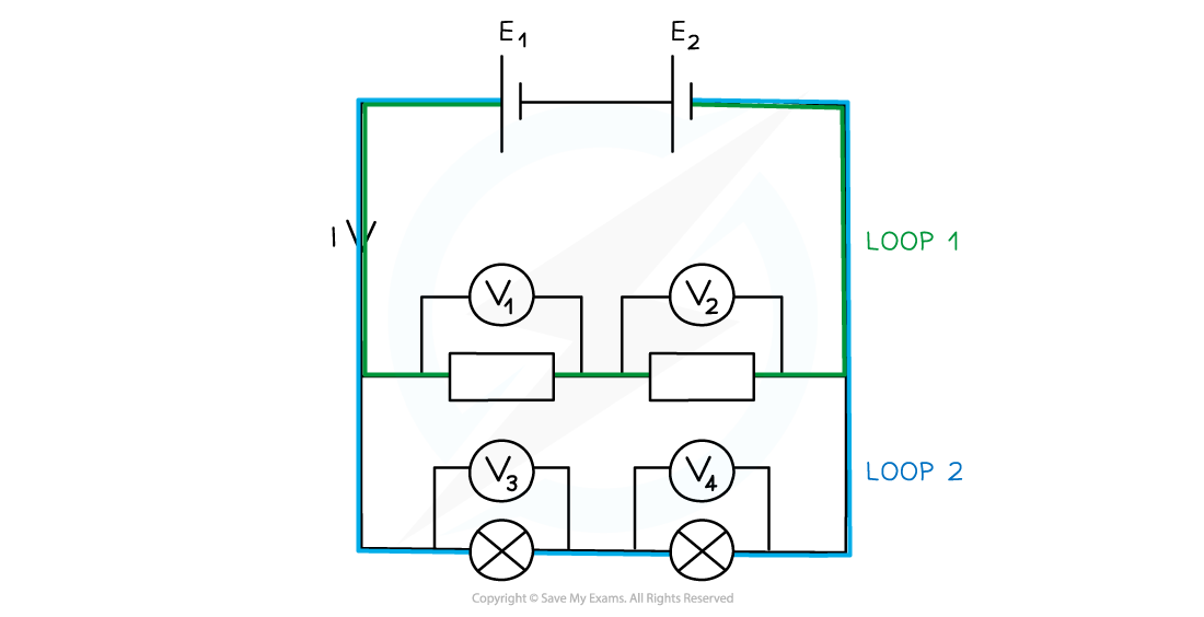
Parallel circuit, voltage same across each closed loop
Sum of voltages in each closed circuit loop equal to the total e.m.f of the power supply.
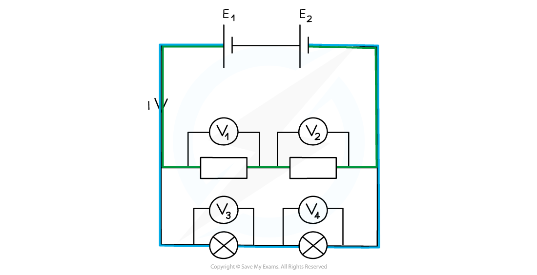
What does a closed-circuit loop act as and what is parallel circuit made up of?
Parallel circuits useful for home wiring systems:
Closed-circuit loop acts as its own independent series circuit and each one separates at a junction. A parallel circuit is made up of two or more of these loops
Single power source supplies all lights and appliances with the same voltage
One light breaks, voltage and current can still flow through for the rest of the lights and appliances
Power P :
PD:
Current:
Electrical power:
What is power in relation to work done?
If the resistors voltage/current doubles what happens to the power?
Rearranging energy and power equation, the energy:
Power P : rate of doing work
PD: work done per unit charge
Current: rate of flow of charge
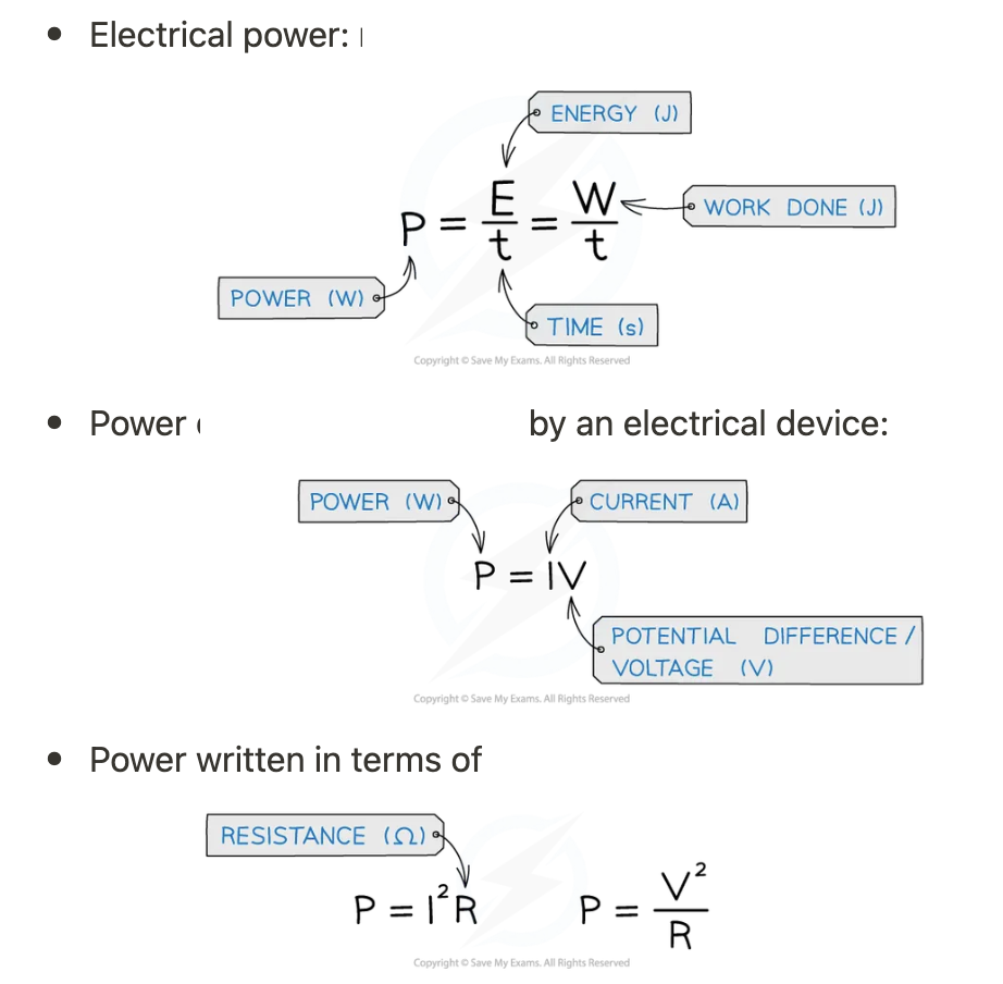
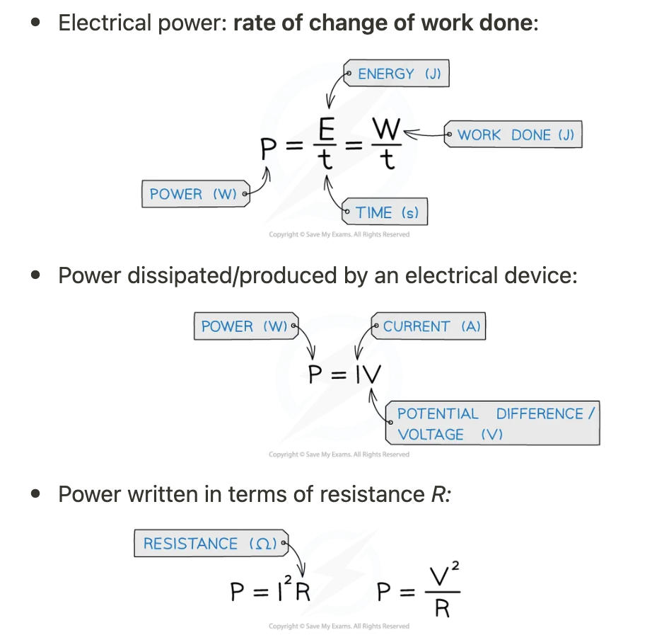
Electrical power: rate of change of work done:
Work done energy transferred so power is the energy transferred per second in an electrical component
Resistor if current/voltage doubles power will be four times as great.
E = VIt
What happens when 2 resistors are connected though series what will the pd be? (kirchhoff’s second law)
What do potential dividers output?
Purpose of potential dividers:
Examples of uses of potential dividers:
Potential divider circuits: ratio
Two resistors connected in series, through Kirchhoff’s Second Law, the pd across power source is divided between them
Potential dividers are circuits which produce output voltage as fraction of its input voltage
Purpose of potential dividers : provide a variable pd, enable a specific pd to be chosen, split the pd of a power source between 2/more components
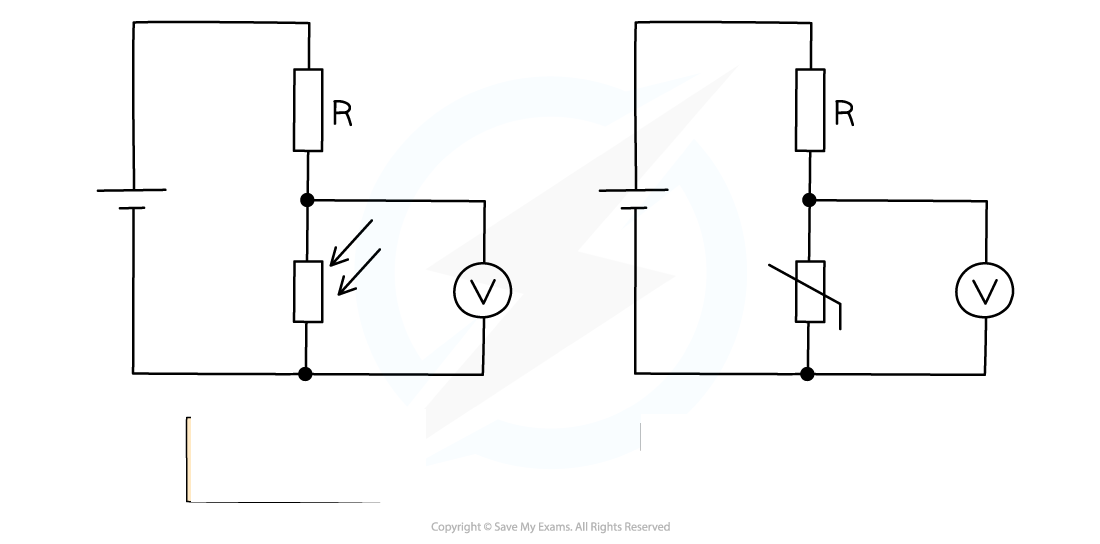
Potential dividers used widely in volume controls and sensory circuits using LDRs and thermistors
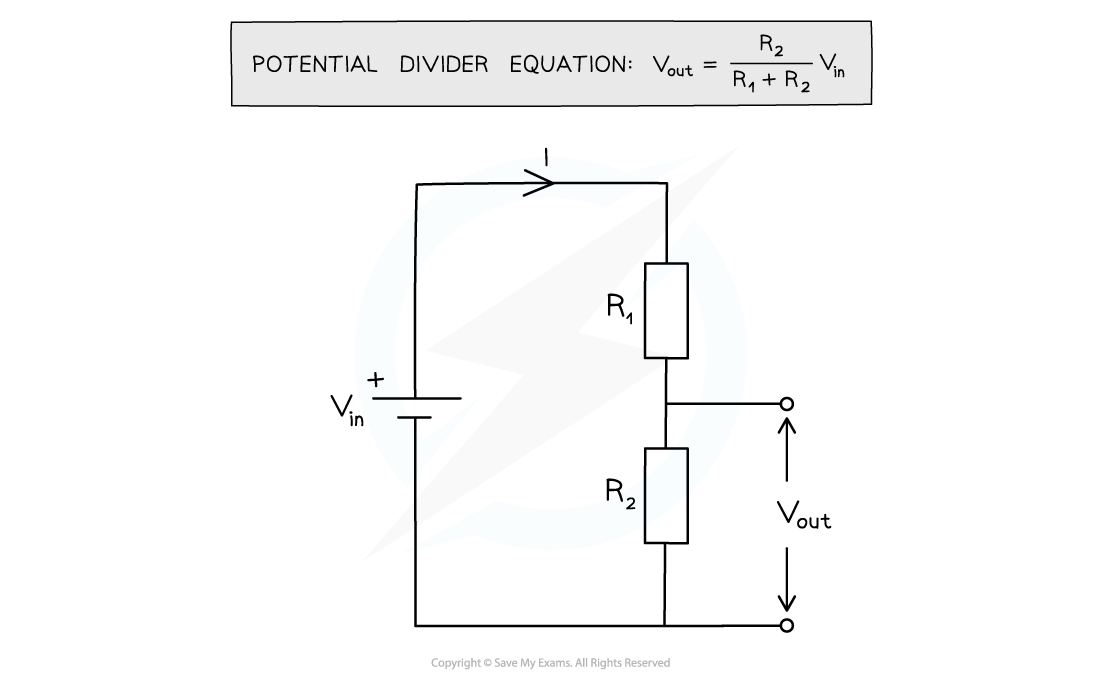
Potential divider circuits: ratio of voltage between components equal to the ratio of resistances of the resistors:

R2:
R1:
Vout:
Vin:
Numerator:
Input voltage applied to:
Output voltage Vout measured:
PD V across each resistor depends upon its resistance R:
What will be pd of the large resistor?
If 1 resistor increased what would happen to the pd?
What is pd proportional to?
R2 numerator and resistance of the resistor over Vout
R1 is the other resistance in series
Vout is the output potential difference
Vin is the input potential difference
The numerator has to be the resistance of the resistor over Vout
Input voltage Vin applied to the top and bottom of the series resistors
Output voltage Vout measured from centre to the bottom of resistor R2
PD V across each resistor depends upon its resistance R:
The resistor with the largest resistance will have a greater potential difference than the other one from V= IR
Resistance of 1 of the resistors increased, will greater the share of the pd, whilst other resistor will get a smaller share
In potential divider circuits, p.d across component is proportional to its resistance from V = IR
What is variable and sensory resistors used for?
What can it cause an external component d to do?
What are sensory resistors used in?
Variable and sensory resistors are used in potential dividers to vary the output voltage
Causes an external component to switch on or off e.g. a heater switching off automatically when its surroundings are at room temperature
Sensory resistors used are Light Dependent Resistors (LDRs) and thermistors
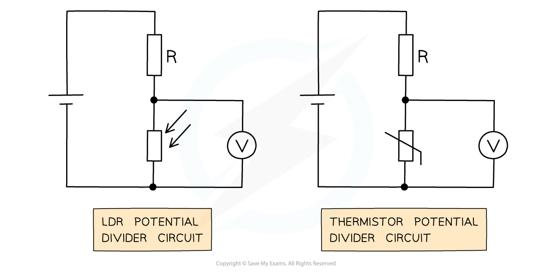
What measures Vout in both ciruits?
What does resistance of LDR vary with?
Higher the light intensity =
What is LDR often used for:
What does the resistance of thermistor vary with?
Hotter thermistor =
Thermistor uses:
Voltmeter in both circuits is measuring Vout
Resistance of an LDR varies with light intensity
Higher light intensity, lower the resistance vice versa
LDR circuit often used for street and security lights
Resistance of thermistor varies with temperature
Hotter thermistor, lower the resistance vice versa
Thermistor circuit used in fire alarms, ovens, digital thermometers
What is the pd Vout from resistor in potential divider circuit proportional to?
What happens to the pd when LDR or thermistor's resistance decreases?
What happens to the pd when LDR/thermistor's resistance increases?
What happens when the pd of the sensory resistor decreases?
Ohm’s law V = IR, the pd Vout from resistor in potential divider circuit proportional to its resistance
LDR or thermistor's resistance decreases, the pd through it also decreases
LDR/thermistor's resistance increases, the pd through it increases
Since the total p.d of the components must be equal to V, if the p.d of the sensory resistor decreases then the p.d of the other resistor in the circuit must increase
What happens when charge passes power supply?
Emf (_) (____):
What is emf equal to?
How is emf measured?
When charge passes through power supply e.g. battery, gains electrical energy
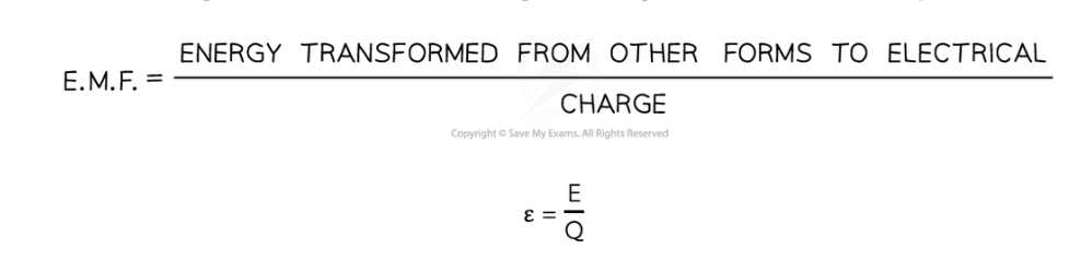
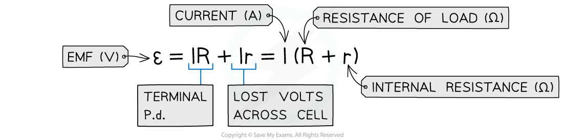
Electromotive force (e.m.f) (ε) (Volts): The amount of chemical energy converted to electrical energy per coulomb of charge (C) when passing through a power supply
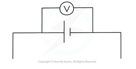
E.m.f equal to pd across cell when no current is flowing
E.m.f measured by connecting a high-resistance voltmeter around terminals of cell in an open circuit:
Terminal potential difference (p.d):
What happens when there is no internal resistance?
Equation:
When a cell has internal resistance, what happens to the terminal pd?
In closed circuit, current flows through cell and ___ develops across the _____ resistance
What does resistance reduce?
Lost volts(little v):
What does internal resistance cause?
conservation of energy:
v =_ - _ = Ir
Emf defined as:
Terminal potential difference (p.d) is the pd across terminals of cell
No internal resistance, terminal p.d is equal to the e.m.f
V = IR
Cell has internal resistance, the terminal p.d always lower than e.m.f
In closed circuit, current flows through cell and pd develops across the internal resistance
Since resistance opposes current, reduces energy per unit charge (voltage) available too rest of the external circuit
Lost volts(little v): The work done per unit charge / coulomb to overcome the internal resistance / resistance inside the battery (when current flows)
Voltage lost in cell due to internal resistance
conservation of energy: v = e.m.f − terminal p.d :
v = ε – V = Ir (Ohm’s law)
E.m.f can therefore be defined as the total, or maximum, voltage available to the circuit
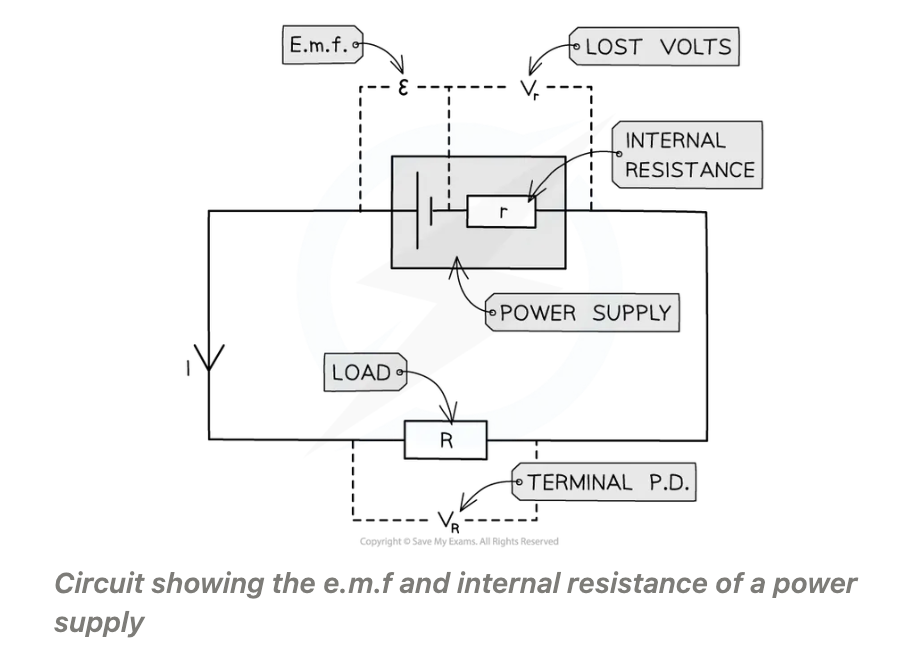
Internal resistance (r):
What does internal resistance cause and overtime?
Resistor R:
r :
ε :
Vr :
VR:
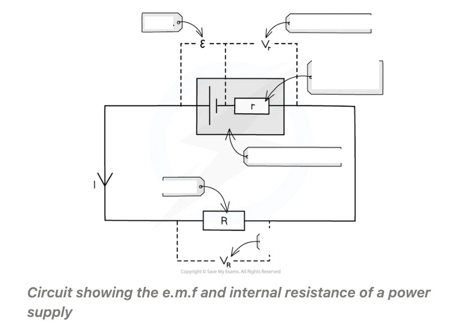
Internal resistance (r): The resistance of the materials within the battery
Internal resistance causes charge circulating to dissipate some electrical energy from power supply itself, cell becomes warm after a period of time
Over time the internal resistance causes loss of voltage/energy loss in a power supply
Resistor R: 'load resistor'
r : internal resistance
ε : e.m.f
Vr : lost volts
VR: p.d across load resistor, same as the terminal p.d