photos
 Call Kai
 Learn
Learn Practice Test
 Spaced Repetition
 Match
Match Flashcards
 Knowt Play
1/33

There's no tags or description
Looks like no tags are added yet.
Name | Mastery | Learn | Test | Matching | Spaced | Call with Kai | Chat |
|---|
No analytics yet
Send a link to your students to track their progress
34 Terms
Alignment of
the mires on a Bausch
and Lomb keratometer.
(a) The view when the
mires are off the principal
meridians. (b) The view
when the mires are on the
principal meridians.
(c) The view when the
plus and minus signs are
overlapping to measure
the ‘horizontal’ and
‘vertical’ radii of
curvatu

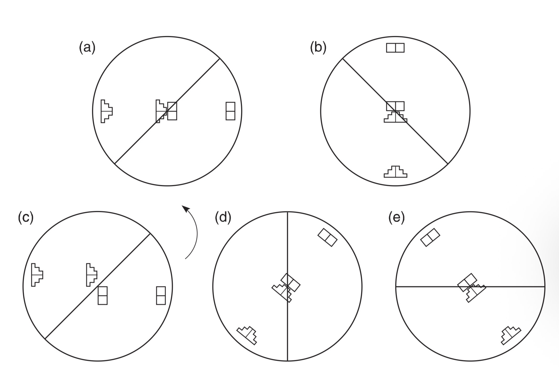
The mire
images as seen on the
Javal Schiotz keratometer.
(a) Aligned mire images
along the horizontal.
(b) Mires from (a) touching
with no overlap. (c) Non-
aligned mire images. (d)
Mire images from (c)
brought into alignment
along an oblique
meridian. (e) Mires from
(d) touching with no
overlap.
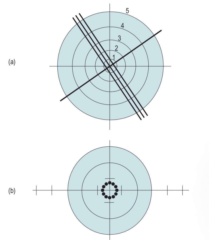
focimeter target
Full distance power
Fitting cross
Major reference point
Distortion area
Full near add power
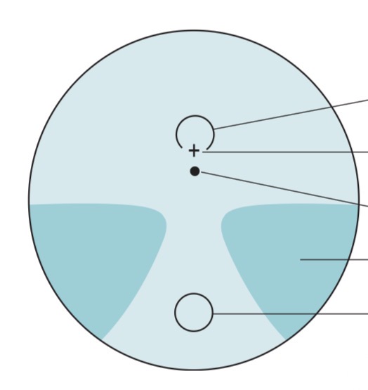
Limbar Zone
Peripheral Zone
Mid-peripheral Zone
+ ContralZone
Corneal Center

Figure 3. Helmholtz keratometer.

Figure 4. The Javal keratometer.

Figure 5. Autorefractometer.
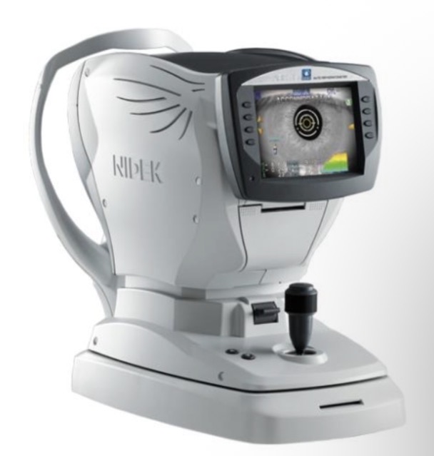
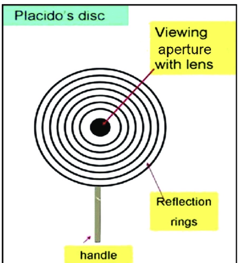
Figure 5. Placido disk keratoscope.
Corneal topographers (Pentacam).
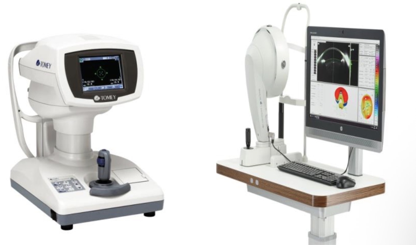
Figure 8. Scheimpflug camera principle.

Color coded topographic maps.
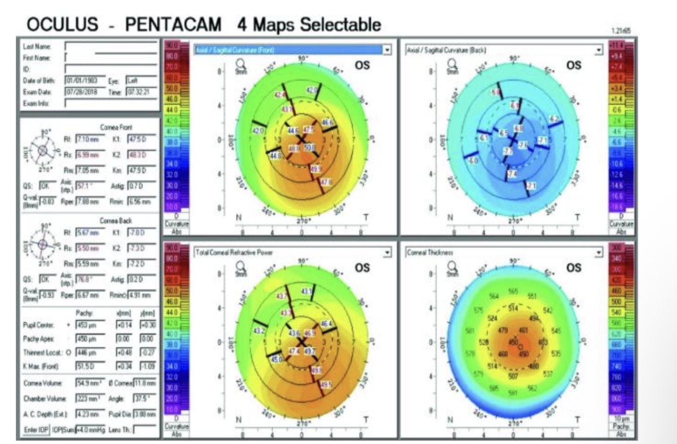
Anterior Sagittal maps.
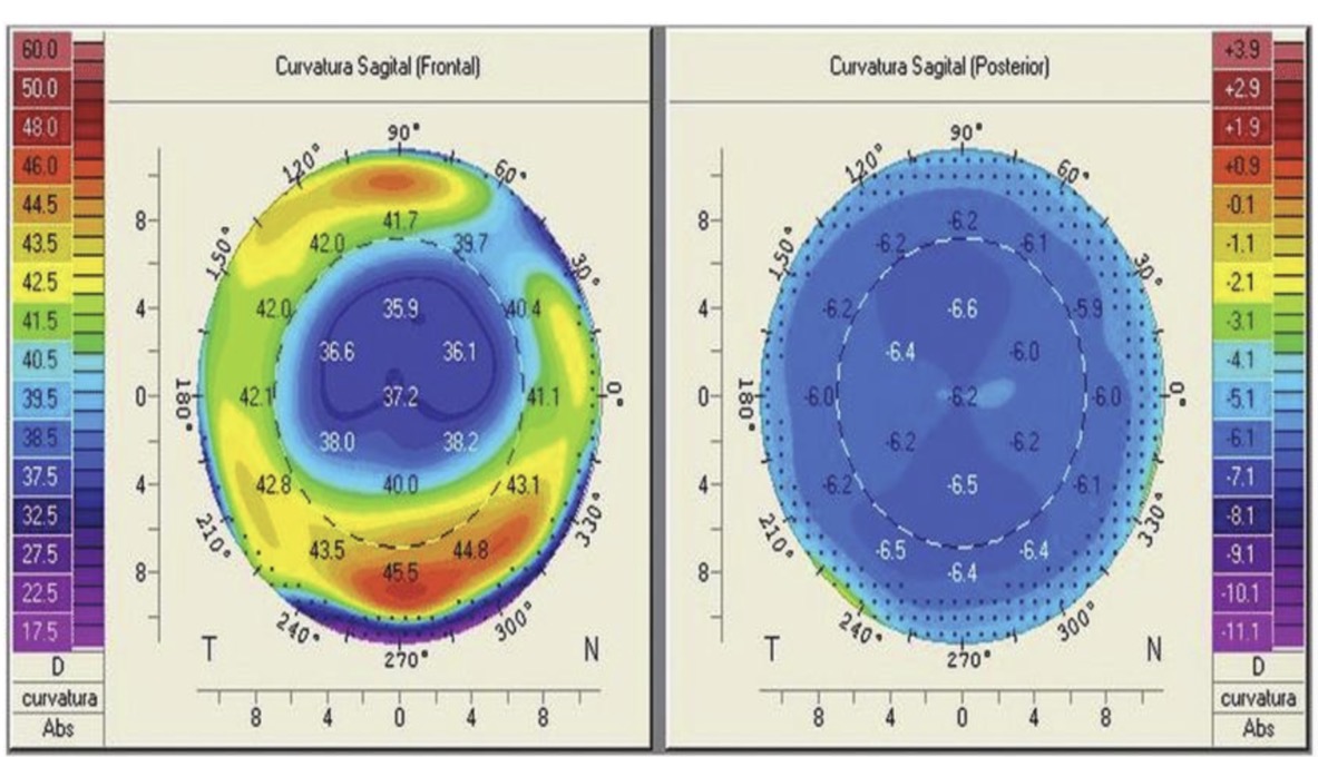
Symmetric bowtie.

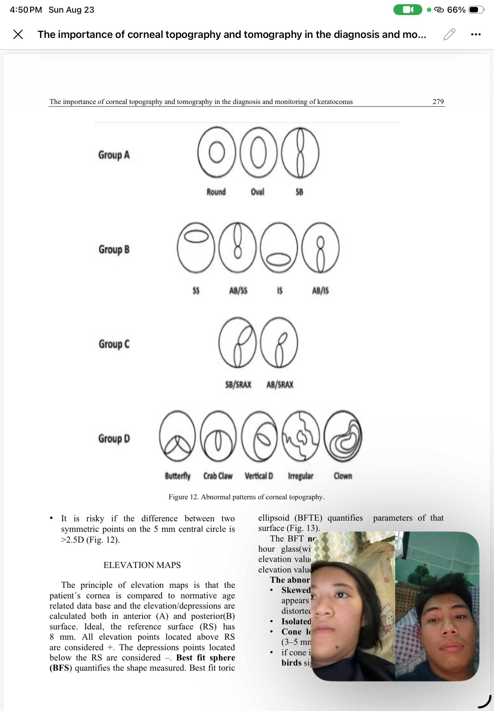
Abnormal patterns of corneal topography.
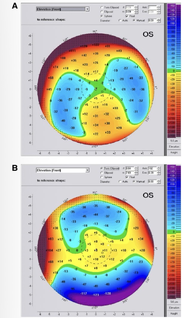
Elevation maps.

Keratoconus

The kissing birds sign.
Pachymetry maps.
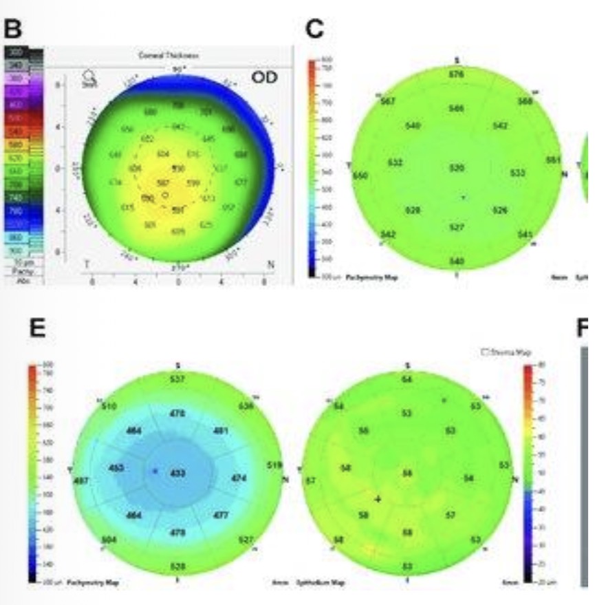
Abnormal patterns in pachymetry maps.

Integrated Indices.

BAD_D display-normal aspect

Abnormal patterns of BAD_D display.
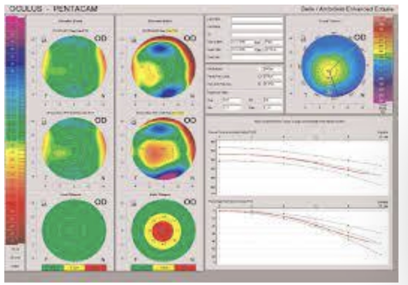
Ambrosio relational thickness.

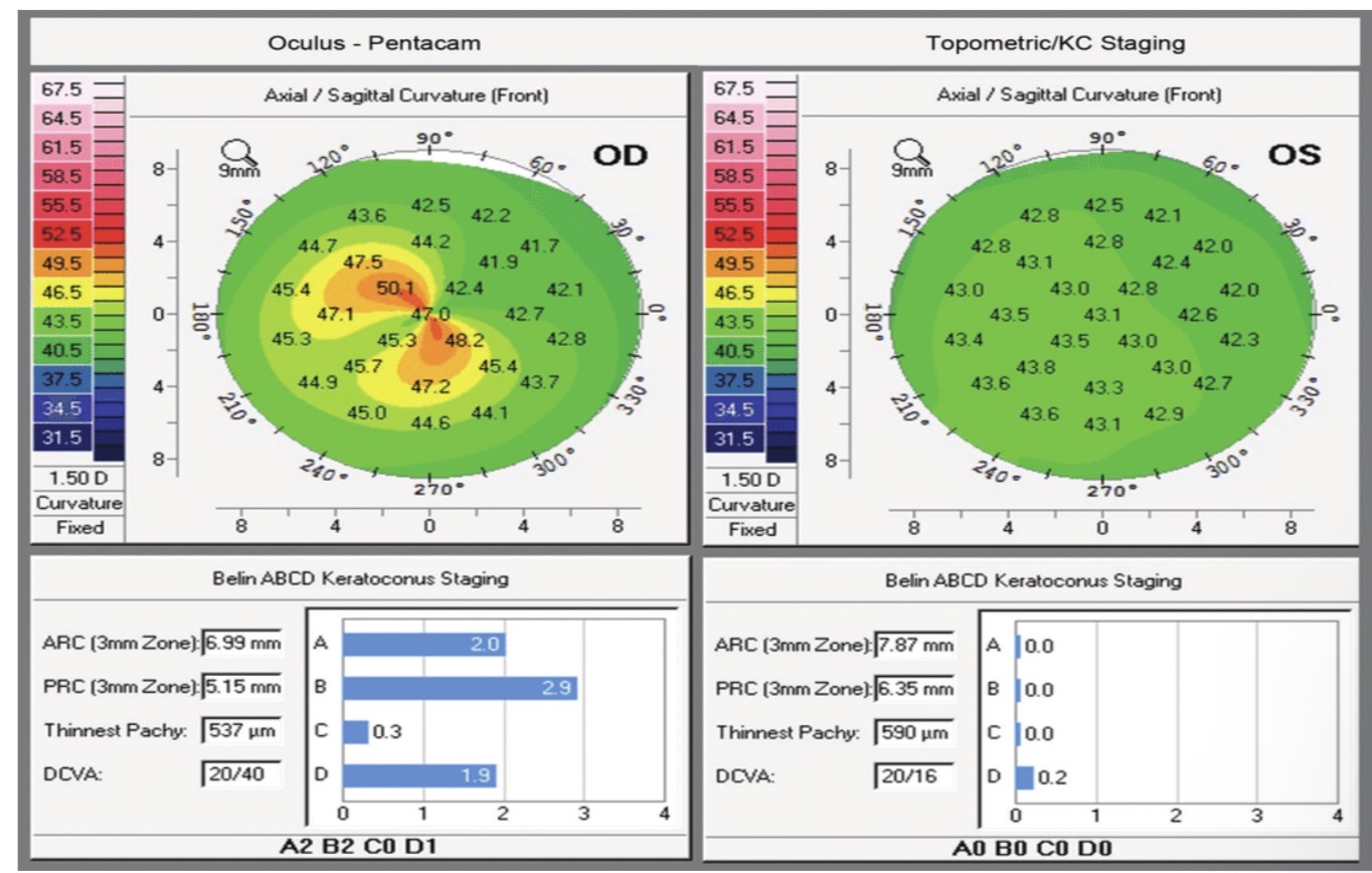
The ABCD classification of keratoconus.
keratometric formula
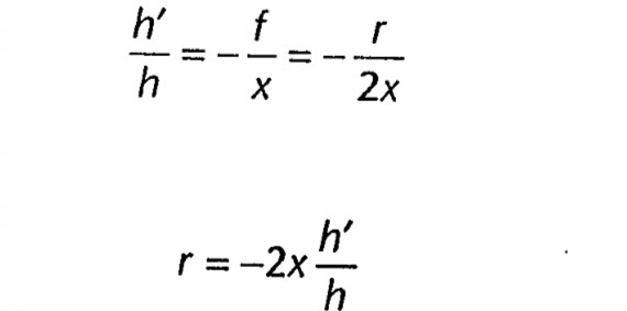
Cornea as a spherical mirror

aperture in thekeratometer optical system
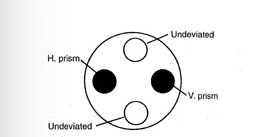
scheiner disk focusing mechanism

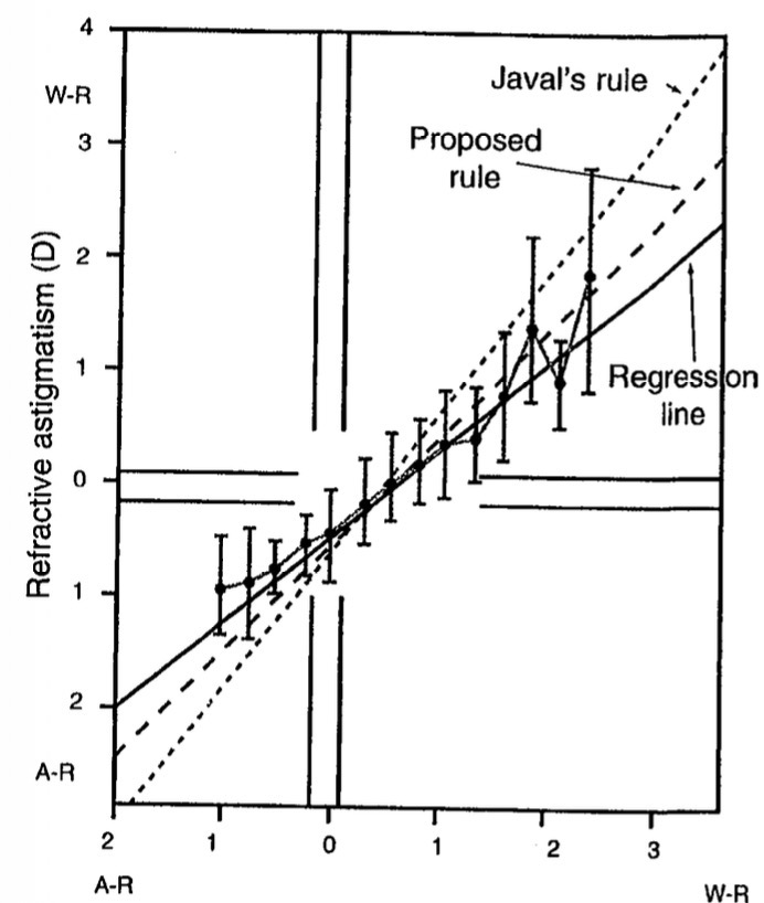
corneal astigmatism

keratometric astigmatism
jackson cross cylinder

schematic eye