EASA ANNEX IV (Part-CAT)
1/86
Name | Mastery | Learn | Test | Matching | Spaced | Call with Kai | Chat |
|---|
No analytics yet
Send a link to your students to track their progress
87 Terms
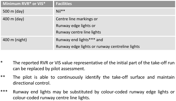
Take-off minima without LVTO approval
Minimum RVR or VIS:
DAY: 500 m with no facilities; 400 m with centreline markings or rwy edge lights or rwy centreline lights
NIGHT: 400 m with rwy END lights AND edge lights/centreline lights
Lowest possible DH/MDH depending on IAP type (system minima)
ILS: 200 ft
LPV: 200 ft
VOR/DME: 250 ft
LNAV/VNAV: 250 ft
LOC: 250 ft
VOR: 300 ft
NDB/DME: 300 ft
LCTR: 350 ft
Runway type minima (PA, NPA, Non-Instrument), lowest DH/MDH
PA: 200 ft
NPA: 250 ft
Non-Instrument: circling minima
Type of runway versus minimum RVR or VIS
PA CAT I: 550 m
NPA: 750 m
Non-Instrument: circling minima
Circling Minima for class A
MDH ≥ 400 ft
RVR ≥ 1500 m
Circling Minima for class B
MDH ≥ 500 ft
RVR ≥ 1600 m
Circling Minima for class C
MDH ≥ 600 ft
RVR ≥ 2400 m
Circling Minima for class D
MDH ≥ 700 ft
RVR ≥ 3200 m
Minimum RVR for visual approach operation
800 m
When do you use the Converted Meteorological Visibility (CMV) instead of RVR?
If the reported RVR is not available, a CMV may be substituted for the RVR, except:
to satisfy the take-off minima; or
for the purpose of continuation of an approach in LVOs.
If the minimum RVR for an approach is more than the maximum value assessed by the aerodrome operator, then CMV should be used.
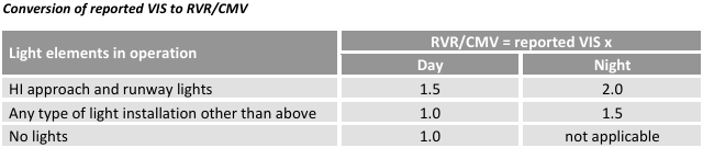
Determination of CMV from visibility
For flight planning purposes, a factor of 1.0 should be used (CMV = VIS)
For any other purposes:
Day
HI approach and runway lights: 1.5
Any other type of light installation: 1.0
No lights: 1.0
Night
HI approach and runway lights: 2.0
Any other type of light installation: 1.5
No lights: N/A
Approach Minima CAT I
RVR ≥ 550 m
DH ≥ 200 ft
Approach Minima CAT II
RVR ≥ 300 m
DH ≥ 100 ft
Approach Minima CAT III A
RVR ≥ 200 m
DH ≥ 50 ft
Approach Minima CAT III B
RVR ≥ 50 m
DH ≥ 0 ft
Approach Minima CAT III C
NO RVR
NO DH
Not used in Europe, where the MINIMUM RVR is 75 m.
Old CAT I/II/III A/III B/IIIC subdivision
The classification does not subdivide CAT III operations into CAT IIIA, IIIB, and IIIC. The actual minima applicable to any operation depends on the aircraft equipment and the specific LVO approval held by the air operator.
The AFM for aircraft certified for CAT III operations will state the lowest usable DH, or no DH. Some AFMs may refer to the previous ICAO classifications as follows:
CAT IIIA: a DH lower than 30 m (100 ft) or no DH and an RVR not less than 175 m;
CAT IIIB: a DH lower than 15 m (50 ft) or no DH and an RVR less than 175 m but not less than 50 m; and
CAT IIIC: no DH and no RVR limitations.
CAT IIIC has not been used in Europe and the minimum RVR in the EU regulations is 75 m.
Define new IAP subdivision (A/B, 2D/3D)
Type A: DH ≥ 250 ft
Type B: DH < 250 ft
2D: lateral guidance only
3D: lateral and vertical guidance
What are the requirements for CAT II/III approaches
Radio Altimeter capable of determining DH
RA callouts below 200 ft
At least 2 flight crew members
Low visibility conditions definition
Low visibility conditions means meteorological conditions with a runway visual range (RVR) less than 550 m.
At DH, what must be visible in order to continue the descent? (LVO)
For CAT II operations and CAT III operations conducted with fail-passive flight control system:
Segment of at least three consecutive lights of the centre line of the approach lights or TDZ lights or runway centre line lights or edge lights or a combination of these; and
A lateral element of the ground pattern, such as an approach lighting crossbar, or the landing threshold, or a barrette of the TDZ lighting unless the operation is conducted using a HUD or an equivalent system to touchdown.
For CAT III operations conducted either with fail-operational flight control systems or with a fail-operational hybrid landing system using a DH:
at least one centre line light to be attained and maintained by the pilot.
LVTO and Specific Approval LVTO RVR required
Take-off operations are classified as ‘normal take-off operations’ with an RVR at or above 550 m and ‘LVTO operations’ with an RVR below 550 m. Only LVTO operations in an RVR of less than 400 m require a specific approval.
At what height do you make the final checklist and MA review during a circling approach?
500 ft AGL
What is the altitude above the aerodrome below which the approach can be continued at commander’s discretion in case of temporarily failed or downgraded GROUND equipment?
1000 ft AAL
Maximum bank angle for a stabilised approach?
30 degress
Maximum variations in the ROD for a stabilised approach?
Variations should not exceed 50% of the target ROD
Maximum ROD for a stabilised approach in the FAS?
1000 fpm, in case of higher than normal approach GS (i.e. compliance with ATC speed restrictions) an higher ROD can be maintaned but must be briefed in advance.
At what height should the airplane be stabilised for landing?
Normally 500 ft AAL, for approach operations without visual reference with the ground 1000 ft AAL
For an RNP APCH using Baro VNAV altimeter readings should not differ more than:
100 ft at or before the FAF
Maximum XTK deviation for a RNAV/RNP procedure?
± 0.5 RNP value for the procedure;
up to 1 RNP value in case of brief deviations such as turns
Maximum vertical deviation for a RNAV/RNP approach?
± 75 ft or half-scale deflection at or below 1000 ft AAL, unless the crew has the visual references required to continue the approach.
At what distance from the FAF must the a/c be established on the final approach track in order to accept “Direct to” clearances to the IF?
2 NM
Can a pilot accept a “Direct to” clearance to the FAF?
No
Maximum angle to transition (to and from) an offset track enroute?
45°
An RNP APCH operation should be discontinued if: (3 cases)
Navigation system failure is annunciated (e.g. warning flag);
Lateral or vertical deviations exceed the tolerances;
Loss of the on-board monitoring and alerting system.
Unless sufficient visual reference to continue the approach has been established.
Above what height may the crew decide to continue the approach to a revised minima in case of loss of vertical guidance?
Above 1000 ft AGL → switch LNAV minima
Below 1000 ft AGL → go-around
What are the differences between Noise Abatement Departure Procedures (NADP) 1 and 2?
NADP1: close-in noise abatement objective, initial thrust reduction at ≥ 800 ft AAL, flap/slat retraction and acceleration at ≤ 3000 ft AAL, then accelerate to en-route climb speed
NADP2: distant noise abatemente objective, flap/slat retraction and acceleration at ≥ 800 ft AAL, thrust reduction after first flap retraction, then accelerate to en-route climb speed
For each type of NADP (1 or 2) a single climb profile should be specified for use at all aerodromes. NADP 1 and 2 may be identical.
NADP - Minimum altitude of the first pilot action and maximum altitude of the end of the procedure?
(NADP 1) ≥ 800 ft AAL (usually power reduction with or without acceleration)
(NADP 2) ≤ 3000 ft AAL
Do NADP rules address lateral profile of the departure procedure?
No, the rule addresses only the vertical profile of the departure procedure.
Define RNAV/RNP “X” designation
It represents the lateral navigation accuracy (total system error) in NM, which is expected to be achieved at least 95 % of the flight time by the population of aircraft operating within the airspace, route or procedure.
What does MOPSC mean?
Maximum Operational Passenger Seating Configuration
Maximum distance from an adequate aerodrome for twin engine without ETOPS approval? (ISA conditions, still air)
Class A with MOPSC ≥ 20: d flown in 60 minutes at the OEI cruising speed.
Class A with MOPSC < 20: d flown in 120 minutes (or 180 minutes, subject to approval) at the OEI cruising speed.
Class B or C, the lesser of: d flown in 120 minutes at the OEI cruising speed or 300 NM.
Minimum Obstacle Clearance Altitude (MOCA)
KSS formula
MOCA is the sum of the maximum terrain or obstacle elevation, whichever is higher, plus:
1000 ft for elevation ≤ 6000 ft
2000 ft for elevation > 6000 ft
(corridor width depends on distance and navaid)
Jeppesen formula
Route MORA:
1000 ft for elevation ≤ 5000 ft
2000 ft for elevation > 5000 ft
(10 NM either side)
LIDO formula
Minimum Terrain Clearance Altitude (MTCA):
1000 ft for elevation ≤ 6000 ft
2000 ft for elevation > 6000 ft
(5 NM either side for SID and STAR, 10 NM for airways)
What is the lowest MOCA to be indicated?
2000 ft
Minimum en-route altitude (MEA)
MEA is based on the elevation of the highest point along the route segment, plus:
1500 ft for elevation ≤ 5000 ft
2000 ft for elevation > 5000 ft but ≤ 10000 ft
10% of elevation + 1000ft for elevation > 10000 ft
(10 NM either side up to 100 NM, after 100 NM 10% of segment length up to 60 NM)
During flight preparation for PBN operations, what’s the maximum duration of predicted continuous loss of fault detection that can be ignored?
With RAIM: the availability should be checked during preflight planning and in case of a predicted continuous loss of fault detection of > 5 minutes, the flight planning should be revised to reflect the lack of full PBN capability for that period.
For RNP 4 with only GNSS sensors: the maximum allowable time for which FDE capability is projected to be unavailable on any one event is 25 minutes.
For RNAV 10 operations: time limit declared for the inertial system
What is the duration of an AIRAC cycle?
28 days
All fuel/energy schemes shall comprise 3 elements, these are:
(1) a fuel/energy planning and in-flight re-planning policy;
(2) an aerodrome selection policy; and
(3) an in-flight fuel/energy management policy.
What are the 3 possible fuel schemes?
An operator can choose between three different fuel schemes:
(a) Basic fuel scheme: all the AMC that apply to the basic fuel scheme.
(b) Basic fuel scheme with variations: when an operator decides to deviate fully or partly from the basic fuel schemes, the AMC for basic fuel schemes with variations apply to the specific deviation.
(c) Individual fuel scheme: when an operator wishes to apply an individual fuel scheme, the AMC for the individual fuel scheme apply; for the part of the scheme where the operator still follows the basic fuel scheme, the operator should apply the AMC referred to in (a) and (b).
Basic fuel scheme
Taxi fuel
Trip fuel
Contingency fuel: required for unforeseen factors; the greater of:
5% of the planned trip fuel
fuel to fly for 5 minutes at holding speed at 1500 ft above the destination aerodrome
Alternate fuel:
≥ 1 alternate → fuel from destination to alternate
No alternate → fuel to hold at destination for 15 minutes at 1500 ft above the destination
Final reserve fuel calculated at holding speed at 1500 ft above the alternate or destination (in case of no alt):
Reciprocating engines → 45 minutes
Turbine engines → 30 minutes
Additional fuel: required to land at an ERA
Extra fuel
Discretionary fuel
What does the trip fuel include?
Trip fuel:
for t/o and climb to the cruising level;
from TOC to TOD, including step climbs;
from TOD to where the approach procedure is initiated;
for making the approach and landing.
How is contingency fuel calculated in the basic scheme?
The greater of:
5% of the planned trip fuel
fuel to fly for 5 minutes at holding speed at 1500 ft above the destination aerodrome
What does the alternate fuel include?
Fuel:
for missed approach at destination;
for climb to TOC;
from TOC to TOD;
from TOD to approach;
for the approach and landing into alternate.
What is the amount of final reserve fuel required?
Final reserve fuel calculated at holding speed at 1500 ft above the alternate or destination (in case of no alt):
Reciprocating engines → 45 minutes
Turbine engines → 30 minutes
What does the additional fuel include in the basic scheme?
Fuel that allows the aeroplane to proceed, in the event of an engine failure or loss of pressurisation, from the most critical point along the route to a fuel en route alternate (fuel ERA) aerodrome in the relevant aircraft configuration, hold there for 15 minutes at 1500 ft above the ERA elevation in standard conditions, make an approach, and land.
How can the the taxi fuel be calculated in the basic scheme with variations?
The operator may use statistical taxi fuel.
How is the contingency fuel calculated in the basic scheme with variations?
The contingency fuel should be the fuel described in points (c)(1) or (c)(2), whichever is higher:
(1) an amount of fuel that should be either:
not less than 3% of the planned trip fuel, or in the event of in-flight re-planning, 3% of the trip fuel for the remainder of the flight provided that a fuel en route alternate (fuel ERA) aerodrome is available; or
an amount of fuel sufficient for 20-minute flying time based upon the planned trip fuel consumption; or
an amount of fuel based on a statistical fuel method that ensures an appropriate statistical coverage of the deviation from the planned to the actual trip fuel; prior to implementing a statistical fuel method, a continuous 2-year operation is required during which statistical contingency fuel (SCF) data is recorded;
or
(2) an amount of fuel to fly for 5 minutes at holding speed at 1500 ft (450 m) above the destination aerodrome in standard conditions.
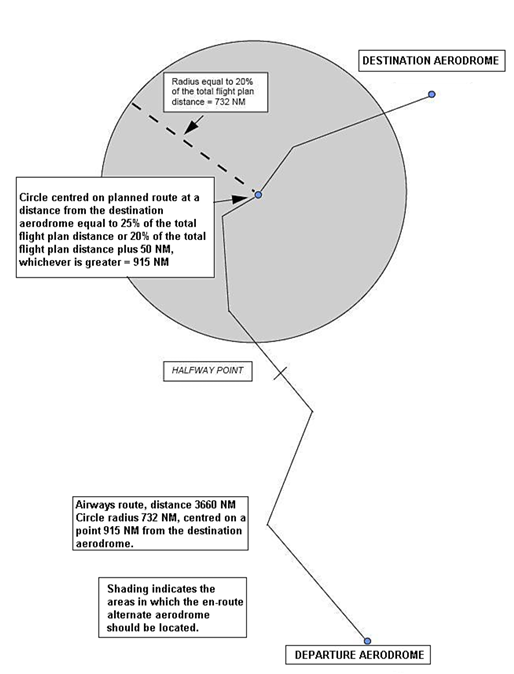
State the location of the fuel ERA to reduce the contingency fuel to 3%.
The fuel en route alternate (fuel ERA) aerodrome should be located within a circle with a radius equal to 20% of the total flight plan distance; the centre of this circle lies on the planned route at either:
a distance from the destination aerodrome equal to 25% of the total flight plan distance; or
at least 20% of the total flight plan distance plus 50 NM;
whichever is greater.
All distances should be calculated in still-air conditions.
What is the RCF procedure?
RCF stands for Reduced Contingency Fuel. The operator defines a destination 1 (commercial destination), a destination 2 (optional refueling destination) and a decision point along the route between departure and destination 1.
How do you calculate the required usable fuel for RCF?
The required usable fuel should be greater than the sum in points (1) or (2):
(1) the sum of:
taxi fuel;
trip fuel to the destination 1 aerodrome via the decision point;
contingency fuel equal to not less than 5% of the fuel that is estimated to be consumed from the decision point to the destination 1 aerodrome;
alternate fuel for destination 1 alternate fuel or no alternate fuel if the remaining flying time from the decision point to destination 1 aerodrome is less than 6 hours;
FRF;
additional fuel;
extra fuel;
discretionary fuel; or
(2) the sum of:
taxi fuel;
trip fuel to the destination 2 aerodrome via the decision point;
contingency fuel from the departure aerodrome to the destination 2 aerodrome (calculated as the higher of: 3% - 20 min flight time - statistically; or 5 min hold at 1500 ft over destination 2);
alternate fuel if a destination 2 alternate aerodrome is required;
FRF;
additional fuel;
extra fuel;
discretionary fuel.
Take-off alternate for basic fuel scheme?
The take-off alternate aerodrome should not be farther from departure than:
(1) for two-engined aeroplanes:
1-hour flight time at an one-engine-inoperative (OEI) cruising speed; or
the extended-range twin operations (ETOPS) diversion time that is approved in accordance with Subpart F of Annex V (Part-SPA) to Regulation (EU) No 965/2012, subject to any minimum equipment list (MEL) restriction, up to a maximum of 2-hour flight time at OEI cruising speed ; and
(2) for three- or four-engined aeroplanes, 2-hour flight time at an all-engines-operating cruising speed;
(3) for operations approved in accordance with Annex V (Part-SPA), Subpart L SINGLE-ENGINED TURBINE AEROPLANE OPERATIONS AT NIGHT OR IN IMC (SET-IMC), 30 minutes flying time at normal cruising speed.
All speeds are calculated according to the AFM in ISA and still-air conditions using the actual take-off mass.
How many destination alternate aerodromes must be selected for the basic fuel scheme?
For each IFR flight, at least 1 destination alternate aerodrome. In case the safety margins* are not met 2 destination alternate aerodromes must be selected.
*safety margins: meteorological conditions above planning minima in the period between ETA ± 1 hour
In which case can the operator operate with no destination alternate?
When the destination aerodrome is an isolated aerodrome or when the following two conditions are met:
(1) planned flight time ≤ 6 hours or, in the event of in-flight re-planning, the remaining flying time ≤ 4 hours; and
(2) two separate runways are usable at the destination aerodrome and in the period between ETA ± 1 hour:
ceiling ≥ 2 000 ft (600 m) or ≥ circling height + 500 ft (150 m), whichever is greater; and
ground visibility ≥ 5 km.
What are the conditions to define an aerodrome as isolated?
If alternate fuel + FRF required to reach the nearest adequate destination alternate aerodrome is more than:
Reciprocating engines → 45 minutes + 15% of flight time or 2 hours, whichever is less
Turbine engines → 2 hours normal cruise consumption above destination aerodrome
Basic fuel scheme safety margins for meteorological conditions
The operator should only select an aerodrome as:
take-off alternate aerodrome; or
destination aerodrome
when in the period between ETA ± 1 hour the weather conditions will be at or above:
RVR or VIS specified in accordance with point CAT.OP.MPA.110*; and
for a type A or a circling operation, ceiling at or above MDH.
*aerodrome operating minima established by the operator (the one on the charts)
The operator should only select an aerodrome as:
destination alternate aerodrome;
fuel ERA aerodrome; or
isolated destination aerodrome
when in the period between ETA ± 1 hour the weather conditions will be at or above the planning minima.
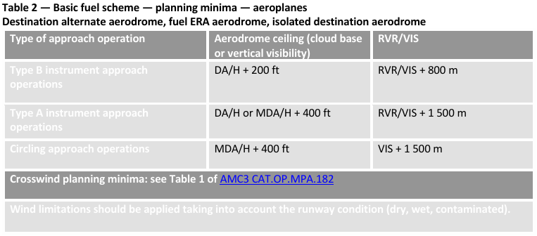
Planning minima for basic fuel scheme
Type B → Ceiling ≥ DA/H + 200 ft, RVR/VIS ≥ + 800 m
Type A → Ceiling ≥ DA/H + 400 ft, RVR/VIS ≥ + 1500 m
Circling → Ceiling ≥ MDA/H + 400 ft, VIS ≥ + 1500 m
In which case should the operator determine a Point of No Return (PNR)?
Whenever the operator’s fuel planning policy includes an isolated aerodrome.
What is the required usable fuel for pre-flight calculations when determining the PNR for an isolated aerodrome?
Whichever is greater:
(1) the sum of:
taxi fuel;
trip fuel from the departure aerodrome to the isolated aerodrome via the PNR;
contingency fuel that is calculated in accordance with the operator’s current fuel scheme;
additional fuel, if required, but not less than:
Reciprocating engines → 45 minutes + 15% of flight time, including the FRF, or 2 hours, whichever is less
Turbine engines → 2 hours normal cruise consumption above destination aerodrome, including the FRF;
extra fuel; and
discretionary fuel; or
(2) the sum of:
taxi fuel;
trip fuel from the departure aerodrome to the fuel ERA PNR aerodrome via the PNR;
contingency fuel that is calculated in accordance with the operator’s current fuel scheme;
additional fuel, if required, but not less than:
Reciprocating engines → 45 minutes; or
Turbine engines → 30 minutes at holding speed at 1500 ft (450 m) above the fuel ERA aerodrome elevation in standard conditions, which should not be less than the FRF;
extra fuel; and
discretionary fuel.
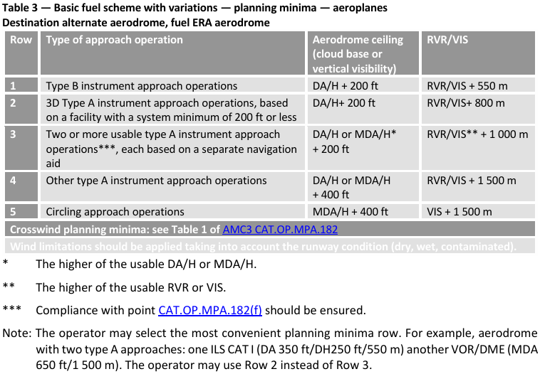
Planning minima for basic fuel scheme with variations for destination alternate aerodrome and fuel ERA aerodrome for flights ≤ 6 hours
Type B → Ceiling ≥ DA/H + 200 ft, RVR/VIS ≥ + 550 m
3D Type A (sys. minimum 200 ft) → Ceiling ≥ DA/H + 200 ft, RVR/VIS ≥ + 800 m
≥ 2 usable Type A based on separate nav-aids → Ceiling ≥ DA/H or MDA/H* + 200 ft, RVR/VIS* ≥ + 1000 m
Other Type A → Ceiling ≥ DA/H or MDA/H + 400 ft, RVR/VIS ≥ + 1500 m
Circling → Ceiling ≥ MDA/H + 400 ft, VIS ≥ + 1500 m
*whichever is higher
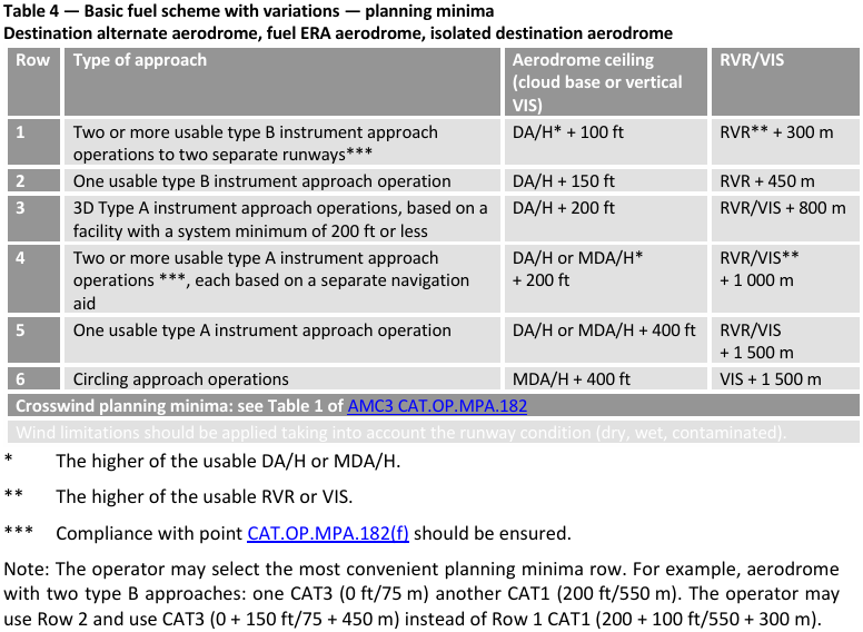
Planning minima for basic fuel scheme with variations for destination alternate aerodrome, fuel ERA aerodrome and isolated destination aerodrome for operators with approval for low-visibility approach operations
≥ 2 usable Type B or 2 separate runways → Ceiling ≥ DA/H or MDA/H* + 100 ft, RVR/VIS* ≥ + 300 m
One usable Type B → Ceiling ≥ DA/H + 150 ft, RVR/VIS ≥ + 450 m
3D Type A (sys. minimum ≤ 200 ft) → Ceiling ≥ DA/H + 200 ft, RVR/VIS ≥ + 800 m
≥ 2 usable Type A based on separate nav-aids → Ceiling ≥ DA/H or MDA/H* + 200 ft, RVR/VIS* ≥ + 1000 m
Other Type A → Ceiling ≥ DA/H or MDA/H + 400 ft, RVR/VIS ≥ + 1500 m
Circling → Ceiling ≥ MDA/H + 400 ft, VIS ≥ + 1500 m
*whichever is higher
Under PBN operations, when can a destination alternate aerodrome be selected?
A destination alternate may be selected only if a non-GNSS instrument approach procedure is available either at the destination alternate or at the destination aerodrome.
An aerodrome with only GNSS approaches may be used without a destination alternate if the requirements for operations without a destination alternate are met.
A take-off or an ERA aerodrome with instrument approach procedures that rely on a GNSS may be planned without restrictions.
Define ‘minimum fuel’ and ‘mayday fuel’.
MINIMUM FUEL → the PIC has committed to land at a specific aerodrome and calculated that any change to the existing clearance to that aerodrome may result in landing with less than the planned FRF.
MAYDAY FUEL → when the usable fuel/energy that is calculated to be available upon landing at the nearest aerodrome where a safe landing can be made is less than the planned FRF.
Refuelling with an engine running
Refuelling with an engine running should only be conducted:
when there are no other sources of electrical or pneumatic power to start the engine if shut down;
in accordance with the specific procedures established by the type certificate (TC) holder of the aeroplane;
with aeroplanes that use JET A, JET A-1 or TS-1 fuel types or any other fuel type that has a flash point above 38 °C and is approved by the operators’ competent authority;
with no passengers embarking, on board, or disembarking;
with permission from the aerodrome operator; and in the presence of the aerodrome rescue and firefighting services (RFFSs).
Refuelling with passengers embarking, on board or disembarking
When passengers are embarking, on board, or disembarking, an aircraft should NOT be refuelled/defuelled with avgas (aviation gasoline) or wide-cut type fuel or a mixture of these types of fuel.
For all other types of fuel:
one qualified person should remain at a specified location during refuelling/defuelling operations with passengers on board, and be capable of using emergency procedures for fire protection and firefighting, communications, as well as for initiating and directing an evacuation;
two-way communication between the ground crew that supervises the refuelling and the qualified personnel on board the aeroplane;
the ‘FASTEN SEAT BELT’ signs should be off;
‘NO SMOKING’ signs should be on, together with interior lighting to allow the identification of emergency exits;
passengers should be instructed to unfasten their seat belts and refrain from smoking;
the minimum required number of cabin crew should be on board and prepared for an immediate emergency evacuation;
if fuel vapour is detected inside the aeroplane, or any other hazard arises, refuelling/defuelling should be stopped immediately;
the ground area beneath the exits that are intended for emergency evacuation, as well as slide deployment areas, should be kept clear where stairs are not in position for use in the event of evacuation;
and provision is made for a safe and rapid evacuation.
Crew members at stations
Flight crew members → at station during t/o and landing; during all other phases of flight, they can leave the assigned station if necessary provided at least one pilot remains at the controls of the a/c at all times.
Cabin crew members → during critical phases of flight, each cabin crew member shall be seated at the assigned station and shall not perform any activities other than those required for the safe operation of the aircraft.
Seats, safety belts and restraint systems
Crew members → during t/o and landing and whenever deemed necessary by the commander; during other phases of flight, flight crew members shall keep their seatbelts on while at station.
Passengers → before t/o and landing, during taxiing, and whenever deemed necessary by the commander
Controlled rest time limits
Only one crew member at a time, with restraint on;
No longer than 45 minutes, to limit the actual sleep to around 30 minutes;
Recovery period of 20 minutes to after the rest to recover from sleep inertia, followed by an appropriate briefing;
It should terminate at least 30 minutes before descent.
Use of headset by flight crew members
The headset shall be used as the primary device for voice communications with ATS:
(1) when on the ground:
when receiving the ATC departure clearance via voice communication; and
when engines are running;
(2) when in flight:
below transition altitude; or
10000 ft, whichever is higher;
(3) whenever deemed necessary by the commander.
Use of supplemental oxygen
Flight crew members:
Cabin alt. > 10000 ft for more than 30 minutes; and
Whenever cabin alt. > 13000 ft
In-flight check of the landing distance at the time of arrival
No approach to land shall be continued unless the LDA ≥ 115% LDR for performance class A aeroplanes certified with CS-25 certification specifications.
Runway condition code
6: Dry surface
5: Wet or damp surface (GOOD)
4: Frost, dry snow, or thin slush (MEDIUM TO GOOD)
3: Wet snow, compacted snow, or wet ice (MEDIUM)
2: Slippery wet runway (MEDIUM TO POOR)
1: Poor braking action (POOR)
0: Nil braking capability (extremely slippery, LESS THAN POOR)
What is the required visibility to commence an approach?
There is no prohibition on the commencement of an approach based on the reported RVR or VIS.
Continuation of approach requirements
For aeroplanes, if the reported visibility (VIS) or controlling RVR for the runway to be used for landing is less than the applicable minimum, then an instrument approach operation shall not be continued:
past a point at which the aeroplane is 1000 ft above the aerodrome elevation; or
into the final approach segment (FAS) if the DH or MDH is > 1000 ft.
If the required visual reference is not established, then a missed approach shall be executed at or before the DA/H or the MDA/H.
If a deterioration in RVR or VIS is reported once the a/c is below 1000 ft the normal visual reference requirements apply at the DA/H.
Controlling RVR
The touchdown RVR should be the controlling RVR.
If the touchdown RVR is not reported, then the midpoint RVR should be the controlling RVR.
Where the RVR is not available, CMV should be used.
Visual reference for Type A and Type B CAT I approach operations
At least one of the visual references specified below should be distinctly visible and identifiable to the pilot at the MDA/H or the DA/H:
elements of the approach lighting system;
the threshold;
the threshold markings;
the threshold lights;
the threshold identification lights;
the visual glide path indicator;
the TDZ or TDZ markings;
the TDZ lights;
the FATO/runway edge lights; or
other visual references specified in the operations manual.
Reporting on runway braking action
Whenever the runway braking action encountered during the landing roll is not as good as that reported by the aerodrome operator in the runway condition report (RCR), the commander shall notify the air traffic services (ATS) by means of a special air-report (AIREP) as soon as practicable.
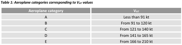
Aeroplane categories corresponding to VAT values
A Less than 91 kt
B from 91 to 120 kt
C from 121 to 140 kt
D from 141 to 165 kt
E from 166 to 210 kt