CS 492 - File Systems
1/73
Earn XP
Description and Tags
encompasses file systems, input output, and disks
Name | Mastery | Learn | Test | Matching | Spaced | Call with Kai |
|---|
No analytics yet
Send a link to your students to track their progress
74 Terms
Requirements of File Systems
Store a very large amount of information (at a reasonable cost)
Information must survive the termination of the process using it
Multiple processes must be able to access information concurrently
4 types of different storage devices
Mechanical rotating hard disk drive (HDD)
Solid state drive (SSD)
Tape (uses sequential access, reading a byte requires all previous bytes to be read first)
Optical disk (obsolete today)
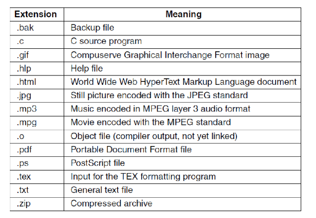
File naming conventions
File extensions (.pdf, .exe, etc.)
File name length
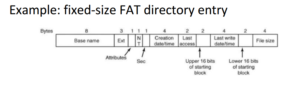
FAT: 8.3 characters (8 for name, 3 for extension), later extended to 255
EXT4: 255 characters
Some special characters not allowed in file names
FAT: No “*/:<>?\| and more
EXT4: No ‘\0’ and ‘/’ or the special names “.“ and “..”
Case sensitivity
FAT: lowercase and uppercase are treated the same
EXT4: lowercase and uppercase are different
File extensions
In Windows they correspond to a file type, so it determines how the file should be open
In Unix they are just conventions, sometimes it determines how a file should be opened but its mostly for the user; the kernel does not care
Different file types
Regular files
Directories
Soft links
Character special files
Modeling serial I/O
Block special files
Modelling the disk drive
File operations
Create/Delete
Open/Close
Read/Write
Append (write to end of file)
Seek (move position within file)
Get/Set attributes
Rename (needs to be atomic)
Directories
Inherently are files themselves, data structures that organize and maintain information about files
File attributes are stored in-band (FAT) or out-of-band (EXT4)
Path names
Hierarchical directory
Uses a name and separator (\, /, >, …)
Can also be done relative to the current (working) directory
“.” represents the current directory, good for relative paths
“..” represents the parent directory
Ex:
Windows: \usr\ast
UNIX: /usr/ast
MULTICS: >usr>ast
Directory operations
Create/Delete
. and .. subdirectories are also created/deleted
Opendir/Closedir
Readdir (reading entries one by one)
Rename
Link/Unlink
Hard link
New name for existing file
Soft link
Windows shortcut equivalent
File system
The file system data (also including metadata) stored in storage (disks)
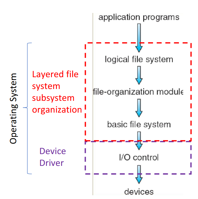
The kernel’s file system subsystem is organized into layers
I/O control
Software/drivers needed to communicate with devices
Basic file system
Read/write and organize/manage the basic blocks of data
File-organization module
Takes the blocks and turns them into files and directories
Logical file system/Virtual file system
Takes the different file systems from the different devices and makes them look the same to the user
Disk and file system layout
First block on a disk is the Master Boot Record (MBR)
Disks can be divided up into one or more partitions, each with an independent file system
On boot, the computer’s BIOS runs first
The BIOS reads a list of storage devices to find a device it can boot from (checking if device has MBR and loads MBR into memory if it does)
The MBR starts executing, reading the partition table to find the bootable partition and loads the PBR/Boot block of that partition, copying it into memory
PBR will find the boot loader within the files and directories, loading it into memory
Boot loader prompts the user for which version of the OS to boot, once selected it will find the kernel and copy it into memory to start executing
Nowadays BIOS + MBR replaced by UEFI + GPT
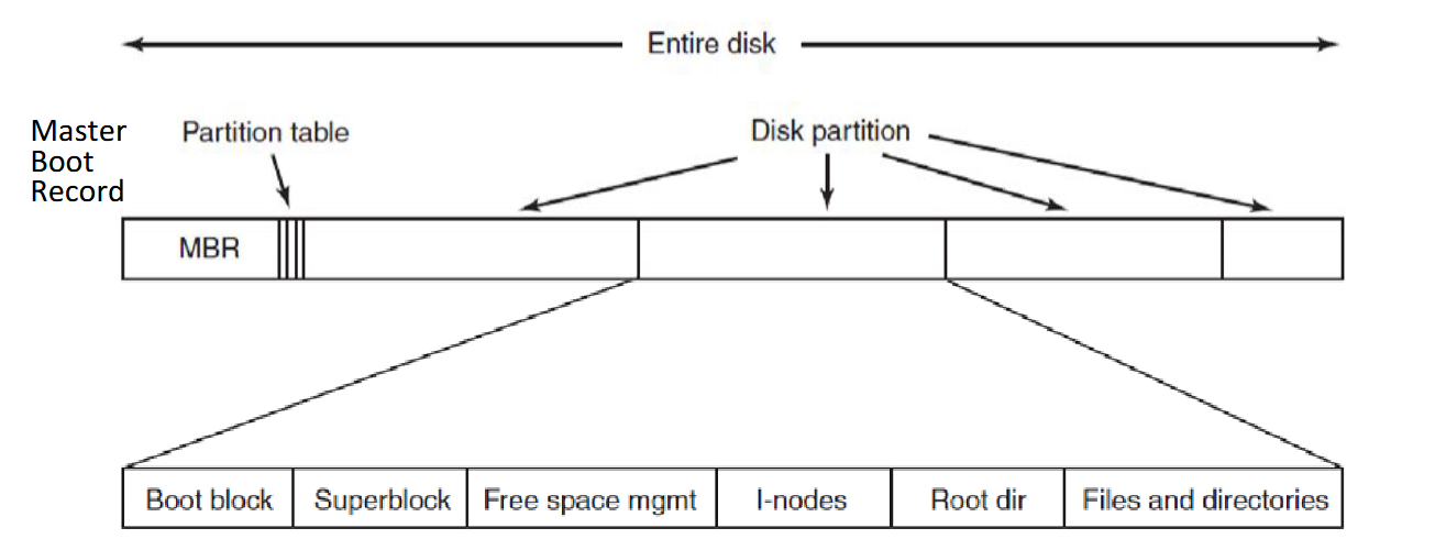
Master Boot Record (MBR)
Contains partition table (size and location of each partition; one partition marked as active / bootable) + boot code that finds and loads PBR
Boot block/Partition Boot Record (PBR)
Boot code needed to find the kernel loader inside the file system of that partition, which itself then finds the kernel
Superblock
stores key parameters about the file system (file system type, number of blocks, etc.)
Computer boot sequence order
BIOS
MBR
PBR
Boot loader
Kernel
User
Addressing
Units: a disk block is the minimal unit of allocation
Physical address: some kind of tuple that identifies a single block on disk
Each disk block has a unique Logical Block Address, looks like a flat sequence of blocks
Kernel driver translates physical addresses to block addresses, the size of the blocks on the disk can differ from the block size the OS uses
Logical file address (LA)
Distance/offset from the beginning of the file (address 0) in bytes
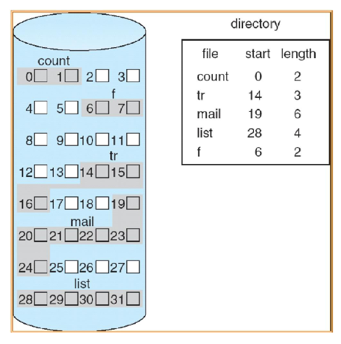
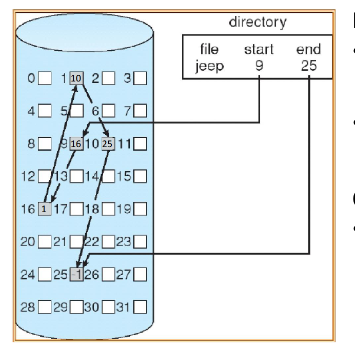
Contiguous Allocation
Each file occupies a set of contiguous disk blocks (all blocks that are part of a file are next to each other)
Entire blocks are used independently of the file size
Accessing the blocks of data for a file requires the corresponding directory entry, name of the file, start block number, and number of blocks being used
Advantages
Simple implementation, only needing starting location and length
Efficient, entire file can be read in a single operation
Disadvantages
Wasteful of space, external fragmentation (i.e. removing files) may require compaction
Files cannot grow, need to know the size upfront as another file could be right next to the current one
Contiguous Allocation formula for mapping logical address to block address
Logical address of file A = LA
LA / Block size = Quotient Q and Remainder R
Block number B = Q + start address of file A in directory
Block offset D = R
Two disk accesses to get the data at address LA
one to get start address of file A from directory
one to read data in block B found at offset D
Linked-List Allocation
Each file is a linked list of blocks
First bytes of a block contain a pointer to the next block
Blocks may be scattered anywhere on the disk
Advantages
Simple implementation, only need starting addresses
Free-space management system, no space is wasted/no external fragmentation
Disadvantages
No efficient random access, as you must go block to block to find the data
Linked-List Allocation formula for mapping logical address to block address
Logical address of file A = LA
LA / (Block size - # of bytes reserved for pointer) = Quotient Q and Remainder R
Block number B = Qth block in the linked chain of blocks, starting from the start block in directory
Block offset D = R + # of bytes reserved for pointer
Q + 1 disk accesses to get the data at address LA
one access to get start block of file A from directory
Q accesses for traversing Q blocks
Linked-List Allocation with Table
Variation of linked list allocation
Data blocks no longer store pointers, instead storing pointers in the File-Allocation Table (FAT)
In the table, each entry corresponds to a disk block number and contains a pointer to the next block or -1
Table on beginning of the disk but copied into the kernel memory for speed
Used on old DOS systems, as well as USB and UEFI system partitions
Advantage
Faster random access (table in memory)
Disadvantage
Entire table has to be in memory, so this is a problem for very large disks
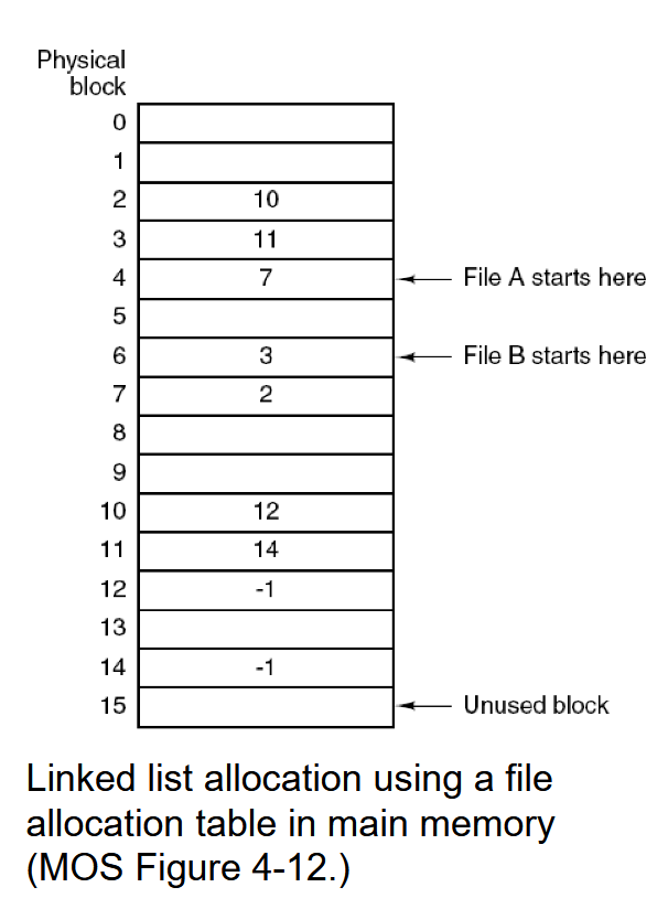
Linked-List Allocation with Table formula for mapping logical address to block address
Logical address of file A = LA
LA / Block size = Quotient Q and Remainder R
Block number B = Qth block in the linked chain of blocks, starting from the start block in directory
Block offset D = R
2 disk accesses + Q memory (FAT) accesses to get the data at address LA
one disk access to get the start address of file A from directory
Q memory accesses in the table to get B
one disk access to read data from block B at offset R
Indexed Allocation
Associate block-sized data structure called index-node (inode) to each file
Directory entries have a filename and corresponding inode number
Lists the attributes of the file
Lists the disk addresses of the file’s blocks
Last address(es) is another block of addresses to allow for dynamically expanding the inode on demand for bigger files
Used on many UNIX file systems and Windows NTFS
Advantages
Efficient random access
Dynamic access without external fragmentation
Lower overhead than FAT
Only need the content of the inode in memory compared to all data blocks
Disadvantages
How to support large files that do not fit the inode?
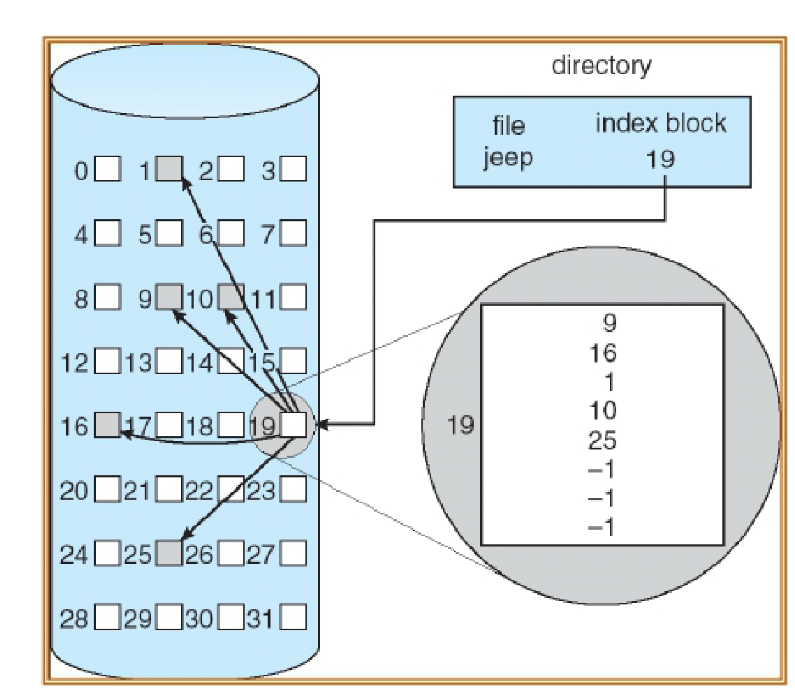
Indexed Allocation with Table formula for mapping logical address to block address (assuming file is small enough to use direct block numbers in the inode)
Logical address of file A = LA
LA / Block size = Quotient Q and Remainder R
Block number B: loop up the Qth entry of the index table to obtain B
Block offset D = R
Three disk accesses to get the data at address LA
one access to get inode address from directory
one access for reading the index table of inode
one access to get data for block B at offset D
Indirection in Indexed Allocation for growing/large files
inode can contain pointer to
direct block (data block)
single indirect (data block from disk now filled with block numbers to direct blocks/data blocks)
double indirect (data block from disk now filled with block number to single indirect blocks)
triple indirect and so on
Allows files to grow and be very large
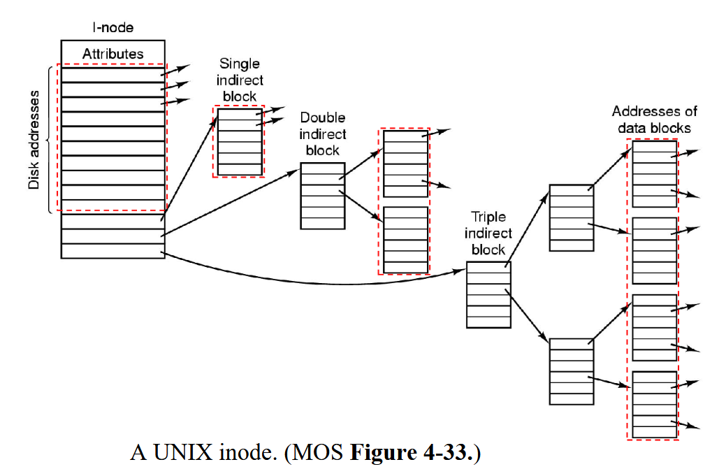
An inode contains 10 direct addresses and these are 8 bytes each. Moreover it contains 2 single indirect addresses. All disk blocks are 1024B. What would the largest possible file be?
10 direct entries
2 single indirect addresses with 1024B / 8B = 128 direct entries each
= 266 direct entries * 1KB = 266KB largest possible file size
Directories Implementation
Map file name to:
Contiguous allocation: the start block address of file
Linked list: the start block of the file
Indexed allocation: the index block
File attributes in a directory are either stored inside the directory with the filename (FAT) or instead in the inode (EXT4, NTFS)
Note that directories are stored as special files
Content of a directory file is directory entries, which can be a directory itself
Directory blocks include one entry for each file within that directory (starting block number of a file)
Directories implementation in inode file systems
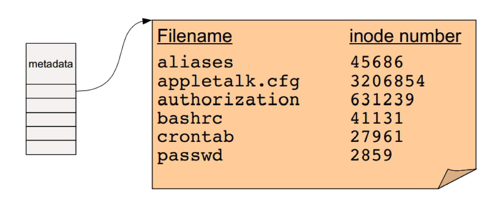
Every file and directory is represented by an inode
Inodes contain the metadata and the location of the file or directory data blocks on disk (note that inodes do not contain file names, the directory entry does)
For a directory, the data blocks store the directory’s file entries: file name + corresponding file number
Root directory “/” has a special inode number, usually 0 or 1
How to find the inode on the disk
Beginning part of the file system (after the superblock) contains all the inodes
block_addr(inode_num) = block_offset_of_first_inode + (inode_num * inode_size)
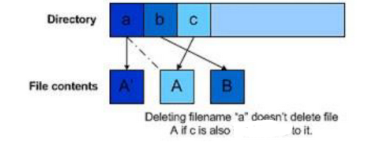
Hard link
Having two different names for the same file that are in different directories or same directory
Possible due to different directory entries storing different file names but pointing to the same inode
All names must be on the same file system (disk partition) since each file system has its own inodes
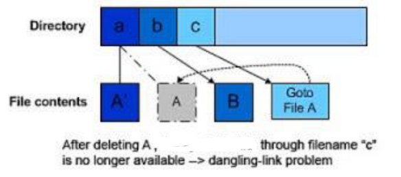
The inode itself keeps a counter of how many filenames/entries correspond with the inode, only when the count reaches zero is the file deleted
Note that processes that are currently using the file will also increment the counter
“.” and “..” can also increment the counter in directories as they are links
Symbolic (Soft) Links
Like a Windows shortcut, a special kind of file indicated by file attribute (special “symlink” bit set) which the content is a string that indicates the location/path name of another file, not inode
Registers
Utilized by kernel device drivers for reading/writing for:
Configuration / initialization (control register)
Read/write data
Check status of device (status register)
Used for communication with CPU with I/O Ports
Buffers
Kernel device driver reads/writes them to move data
ex: GPU RAM for graphics computations and display (framebuffer), packet buffer on a Network Interface Controller
Used for communication with CPU with Memory Mapped
I/O (in same address space as RAM
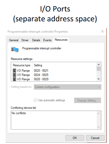
I/O Ports
Each controller register has an I/O port number
Special privileged instructions to access the I/O port space (kernel only, written in assembly), so devices and memory are accessed with different instructions
Separate I/O space and memory space (RAM)
Memory-mapped I/O
All controller registers and buffers mapped into the normal RAM address space
Each controller register is assigned a unique memory address
No actual RAM memory for this address
Such addresses may be at the top of the physical address space
Advantages
Software can read/write to I/O devices as to any other memory location (can just use pointers)
Protection of I/O devices registers and buffers is the same as memory protection
Disadvantages
Need to disable caching for memory-mapped I/O
For one address, RAM controller and I/O devices will all examine the memory reference
Steps for CPU to send data to I/O device
CPU wants to read a word from either memory or I/O port:
Puts the address it needs on the bus address lines
Asserts a read signal on a bus control line
A second signal line to tell I/O space or memory space
If memory space, memory responds to the request
If I/O space, I/O device responds to the request
If there is only memory space (no I/O ports)
RAM controller and every I/O device compares the address lines to the range of addresses that it services
If the address falls in its range, it responds to the request
Since no address is assigned to both memory and I/O device, there should be no conflict
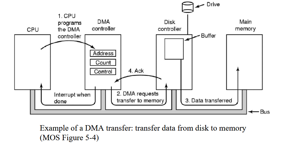
Direct Memory Access (DMA) controller
Transfers data for the CPU
From/to an I/O Device
Between I/O devices
CPU offloads bigger data transfers here and does something else in the meantime
Contains registers to be read/written by kernel
Memory address register
Byte count register
Control registers to indicate the direction of transfer, transfer unit, etc.
CPU writes to the control registers to program the controller to do a transfer
Can do multiple data transfers at once through multiple channels
Multiple sets of registers, one for each transfer channel
CPU loads all sets of registers
Can determine next request to serve via Round-robin or priority schema
Good because they are able to read and write data directly from/to memory and/or I/O devices and is able to be done without using CPU except for initial configuration
Data Transfer Bus Word-at-a-time mode
DMA controller requests for transfer of one word
If the CPU wants the bus, it has to wait until transfer is done
Also called cycle stealing
Data Transfer Bus Block/Burst mode
DMA controller acquires the bus, issues a series of transfers and then releases the bus
Advantage of faster data transfer
Disadvantage of blocking the CPU and other devices for a long time if a long burst occurs (unable to access main memory, but can access caches)
Fly-by mode
DMA controller commands the device controller to transfer data directly to the destination (data only moves once)
Flow-through mode
Data transferred passes through the DMA controller
DMA controller first reads data into an internal buffer/register and then writes it to the destination
This scheme requires an extra bus cycle per word transferred, but it is more flexible
Able to perform device-device copies
Memory-to-memory copies
A DMA controller has five channels. The controller is capable of sending a 32-bit word request in 50 nanoseconds. A response takes equally long. How fast does the bus have to be to avoid being a bottleneck?
50 nanoseconds request + 50 nanoseconds reply = 100 nanoseconds per transfer = 10 million transfers per second
each transfer is 32 bits or 4 bytes, so 4 bytes * 10 million =
40 MB/sec needed to avoid bottleneck
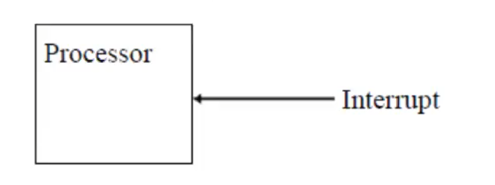
External Interrupts
To interact with I/O devices
ex: CPU requests a data transfer and the devices sends an interrupt when it’s ready
These are normal to have
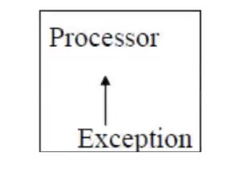
Internal Interrupts
Occurs entirely within the CPU
Also called exceptions, and are used to handle exceptional conditions that occur during the execution of programs; such as:
Divide by zero exception
Arithmetic overflow
Page fault
Invalid instruction
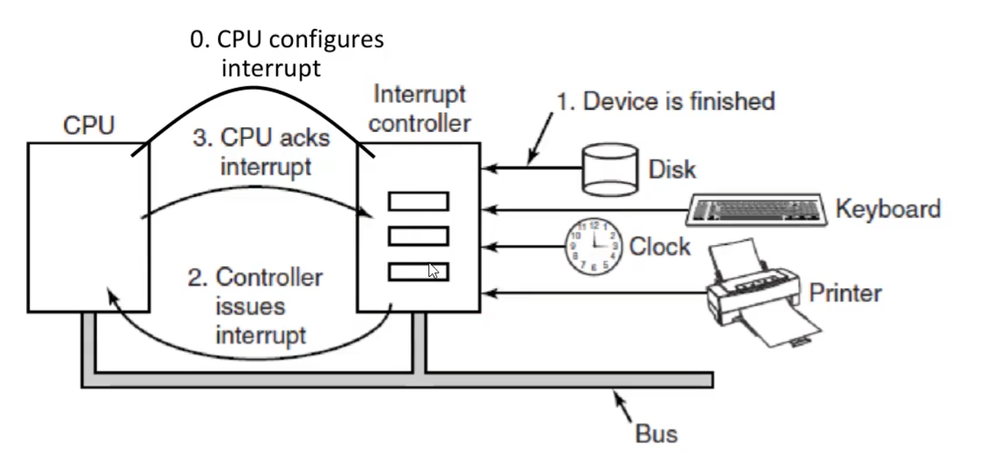
Interrupts
Used to talk with the CPU
Kernel (with the help from CPU) is responsible to save the state of the process, the kernel then processes the interrupt, and then the interrupted process (or a different one) is resumed after the interrupt is handled by the kernel
CPU checks for interrupts after executing every instruction
If an interrupt occurs, the hardware looks up the interrupt vector (configured by the kernel at boot time) to fetch a new program counter
The new program counter points to the code of the right kernel interrupt handler (software interrupt service routine, ISR), which is executed
Goals of I/O software
Device independence
Programs can access I/O device without having to specify the type of device in advance
Uniform naming
Name of file or device should be a string independently of device
Error handling
Errors should be handled as close to hardware as possible (controller first, kernel device driver, …, user program last)
Synchronous (blocking) vs asynchronous (interrupt-driven)
Most physical I/O is asynchronous
Buffering
Involves considering copying, can negatively impact I/O performance
Shareable vs dedicated devices
Some I/O devices, like disks, can be used by many users at the same time
Other devices, such as printers, have to be dedicated to a single user
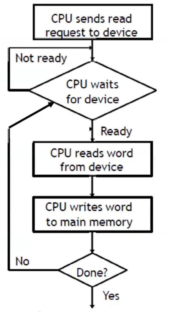
Programmed I/O
CPU writes/reads a byte/word at a time from/to main memory to/from device
CPU makes a request, then waits for the device to become ready
Buses are only one byte/word wide, so the last few steps are repeated for larger transfers
CPU time is wasted as if the device is slow, the CPU may busy wait a long time, constantly polling the device to see if it’s ready to accept another byte/word
Applies to I/O ports, memory-mapped I/O, and hybrid
Advantage of being simple, good for small data transfers
Disadvantage of CPU being unable to do anything else until I/O ends, and inefficiency of polling
Used to implement get_user / put_user
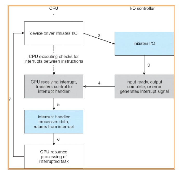
Interrupt-driven I/O
Use of interrupts to let the processor know when the I/O device has completed an operation or has encountered an error, letting the CPU continue with other computations instead of waiting for the slower device
When the device interrupt is received, the CPU can do read/write operations to/from main memory to/from the device for one byte/word
Data transfers from I/O module to CPU, then to memory for (for read, vice versa for write)
Advantages of efficiency, no busy waiting/polling
Disadvantages of interrupt occurring on every character/data transfer, and interrupts take time, so it wastes CPU cycles
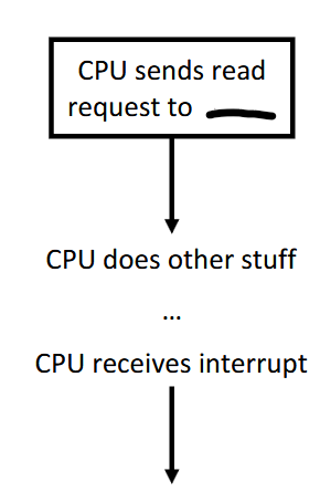
I/O using DMA
DMA controller reads/writes directly from/to system memory
It has access to the system bus independent of the CPU
The CPU has to set up the operation in the DMAC (using either programmed I/O or interrupt-driven I/O)
DMAC does the transfer
Once the transfer is complete, the DMAC notifies the CPU with a single interrupt, so CPU only gets interrupted once at the end of the entire data transfer instead for each data transfer
Advantages of being better than interrupt-driven I/O as most work is done by DMA controller, great for large data transfers
Disadvantage of requiring extra hardware DMA controller (but is standard today)
Used to implement copy_from_user / copy_to_user
A typical printed page of text contains 50 lines of 80 characters each. Imagine that a certain printer can print 6 pages per minute and that the time to write a character to the printer’s output register is so short that it can be ignored. Does it make sense to run this printer using interrupt-driven I/O if each character printed requires an interrupt that takes 50 μsec all-in to service?
50 lines * 80 characters = 4000 characters per page
6 pages per min * 4000 = 24000 characters per min = 400 characters per second, which also mean 400 interrupts per second
50 μsec * 400 = 20000 μsec just for interrupts per second
20000 μsec = 20 milliseconds so about 20/1000 miliseconds which is about 2% of a second of CPU time
It’s fine to use interrupt-driven I/O in this case
Hybrid
I/O port and memory-mapped I/O for the same device
Magnetic disks
HDD, Floppy disk
Moving parts (mechanical)
On physical media, reads and writes are equally fast
Cylinder, head, and sector is now obsolete
Different zones now have a different number of sectors/track, so block addressing is now independent of geometry: local block address
Solid-State drives
Different technologies
NOR
NAND
3D XPoint
Memristor
Multiple interfaces
USB
SATA, mSATA
NVMe (M.2, PCIe)
Nothing is moving (electronic), no mechanical issues
On physical media reads are faster than writes
Optical disks
CD, DVD, Blu-ray
Moving parts (mechanical)
Write-once, read multiple times
If (re-)writeable, writing is way slower than reading
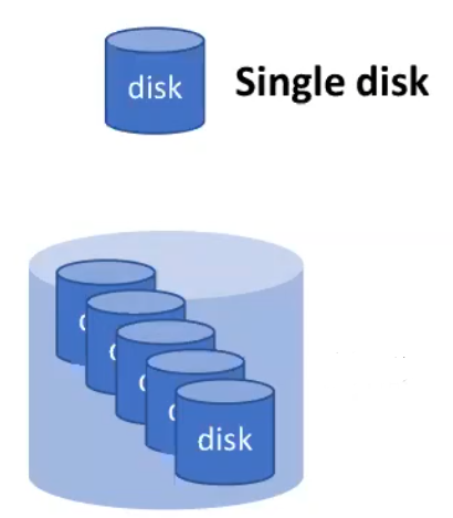
Problems with a single storage device
Slow (in comparison to other components of a computer like CPU)
Modest capacity compared to organizational needs
Unreliable
Discs can totally fail (unable to read/write data)
Bad sectors (cannot read what you have written, spare sectors are available but only a limited quantity)
RAID (Redundant Array of Inexpensive Disks)
Build a storage system as an array of drives, distributing data over multiple drives
Allows data to be read in parallel and be replicated
Appears like a single disk, the system is unaware you are using it, so nothing needs to change
Applies to any storage technology
Hardware RAID controller card
Each drive is connected to the RAID controller
RAID controller can issue read/write in parallel across all disks
Software RAID
Implemented at the operating system level
Cheaper but slower, and typically fewer RAID levels/configurations supported in OS than in specialized hardware
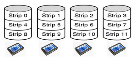
RAID 0
Striping
Data striped (split) across disks
Total storage space across all disks is divided into strips, where every strip includes k sectors
Strips are mapped round-robin to consecutive disks, and multiple strips can be read/written in parallel (parallelism)
No redundancy, if a disk fails you lose a percentage of every file
Small requests result in no performance gains, as if software asks for one sector at a time, there is no parallelism
Bad reliability than a single disk, mean time to failure will be shorter with the more disks added
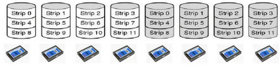
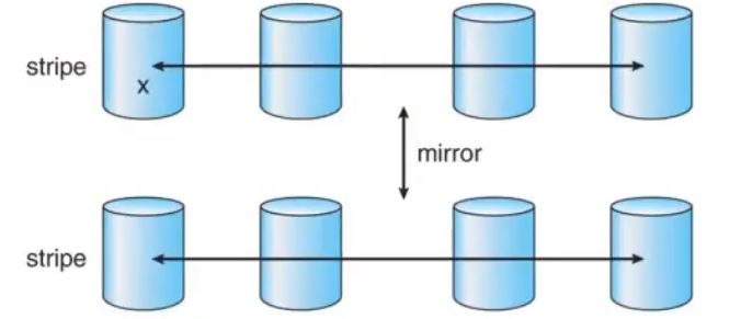
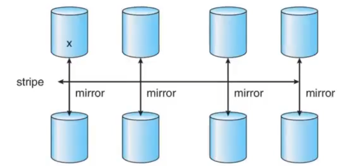
RAID 1
Redundancy by duplicating all the data
Every disk has a mirror disk, storing the same data
A read can be serviced by either of the two disks that contain the requested data
Up to twice as fast as RAID 0 for reading with parallelism
A write must be executed on both disks, but can be done in parallel, so it’s as fast as RAID 0 for writing
Needs double the disks (expensive)
Recovery consists of simply installing a new drive and copying the entire mirror drive to it, which can take a long time
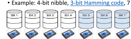
RAID 2
Works on a byte/word basis (not full sector)
Stripes (splits) each byte/word into nibbles (small group of bits), with one bit per disk
Addition of Hamming code bits, one bit per extra disk (error correction code)
Hamming code is used to reconstruct the original data (but Complex and HDDs have internal error correction already)
All drives write in synch the bits for the same nibble
Complex algorithm, all drives have to be rotationally in synch
Needs very performant disk controllers, and is more complex and expensive
Many disks are required for a good ratio of data to Hamming bits
Never used in practice due to these drawbacks
RAID 3
Same as RAID 2 but uses parity bit instead of Hamming code
Given N bits {b1, b2, … bN}, the parity bit P is the bit {0,1} that is an even number of “1” bits in the set {b1, b2, … bN, P}
Parity bit = # of 1 bits in the set modulo 2
If any bit in {b1, b2, … bN} is lost, can use the remaining bits and P to recover it
Store the parity codes in an extra disk
Only able to handle one failing drive and is complex (but reasonable)
All drives have to be rotationally in synch for performance reasons, making it never used in practice

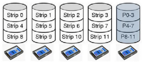
RAID 4
Large strips with a parity strip (XOR)
Similar RAID 3’s parity bit but done at block level rather than bit level, so synch drives are not required
Similar to RAID 0 but with an additional disk for parity
If a drive crashes, lost bytes recomputed with parity
Only able to handle one failing drive
Performs poorly for small updates
One sector changing on a single data disk drive needs to read the corresponding strips on all other data drives to recalculate the parity bits
Or need to compute the difference between old sector and new sector to learn how parity bits must change, which then has to be rewritten on the parity drive
Heavy load on the parity drive, as it is rewritten for any change in the other drives
Rare to see in practice, only works well for small RAID systems
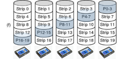
RAID 5
Interleaved data and parity blocks
Rotate the assignment of data blocks and parity blocks among the drives
Avoids the bottleneck of a single disk being used for parity data
Allows multiple reads/writes to occur in parallel
Only able to handle one failing drive
Reconstructing the contents of a failed drive is a complex process, and possibly slow
Commonly used in practice for mid-size RAID systems
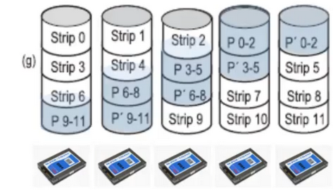
RAID 6
Same idea as RAID 5 but an additional parity block is used
The data is striped across the disks with two parity blocks instead of one, one regular parity and some other kind
Writes are a bit more expensive because of the parity calculations
Reads incur no performance penalty
Protects against two simultaneous disk failures, so commonly used for very large RAID arrays
RAID 0+1
Striped disks are mirrored
When one disk fails, one strip is down and the whole system will fail if any other disk fails on the other side of the mirror, not too reliable
Losing one disk in the RAID 0 system causes it to stop entirely, and transitions to using the mirrored disks
RAID 1+0
Mirrored pairs are striped
After one disk fails, no pair is down, and the whole system will fail only if the other disk in the same pair fails
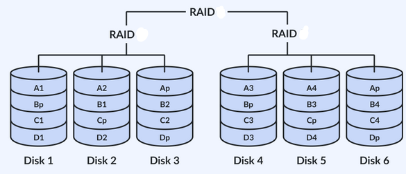
RAID 5+0
Strips with distributed parity and then striped
Stripes across RAID 5 groups
Better reliability due to RAID 5 being able to handle one failed drive before data loss, but striping increases that to two failed drives (one in each strip)
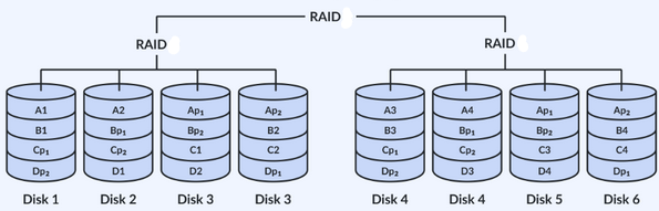
RAID 6+0
Strips with double distributed parity and then striped
Stripes across RAID 6 groups
Better reliability due to RAID 6 being able to handle two failed drive before data loss, but striping increases that to four failed drives (two in each strip)
Mean Time to Failure (MTTF) formula
MTTF disk_array = MTTF single_disk / # disks
A RAID 5 array can fail if two or more if its drives crash within a short time interval. Suppose that the probability of one drive crashing in a given year is p. What is the probability of a k-drive RAID 5 array failing in a given year? (assume disks do not get replaced upon failure)
Probability P0 of all drives remaining healthy is (1-p)^k
Probability P1 of exactly one drive failing is kp * (1-p)^(k-1)
Probability of RAID 5 array failing in a given year P is
1 - P0 - P1 = 1 - (1-p)^k - kp * (1-p)^(k-1)
Assuming p = 1%, with k = 10, then P is 0.42%
Ways of dealing with bad sectors
Internal hardware controller
Operating system
Error correction code for small sector errors
RAID for whole disk-failures
Internal hardware controller (sector errors)
Used to test before the disk is shipped, will check for bad sectors, and for each bad sector will use spare sectors to substitute using a relocation table
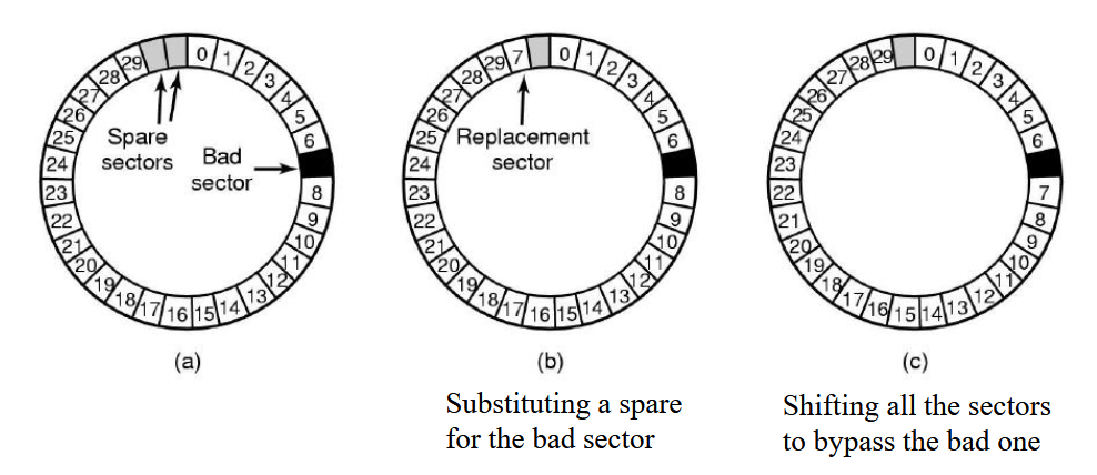
Operating system (sector errors)
Acquires a list of bad sectors, builds remapping tables, and uses the remapping tables when accessing disks